Mini Countryman (F60; 2017 – 2023) – fuse and relay box diagram
Years of production: 2017, 2018, 2019, 2020, 2021, 2022, 2023
Passenger Compartment Fuse Box
Fuse Box Location
The fuses are located behind a cover in the glove compartment.
Fuse Box Diagram
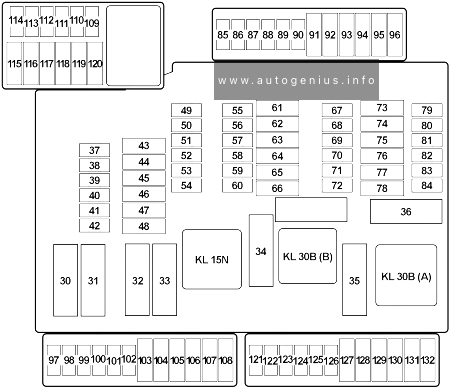
Assignment of the fuses in the glove box
| № | Amps | Protected Component |
|---|---|---|
| 30 | – | – |
| 31 | 50A | Heated Windscreen Relay |
| 32 | 40A | Body Domain Controller |
| 33 | – | – |
| 34 | 40A | Blower Output Stage |
| 35 | 50A | Body Domain Controller |
| 37 | 5A | Parking Brake Button |
| 38 | 5A | Siren with Tilt Alarm Sensor |
| 39 | 5A | Roof Function Centre (Airbag Indicator Lamp) |
| 40 | 5A | Dynamic Stability Control (DSC) |
| 41 | 5A | Instrument Cluster Control Unit |
| 42 | 5A | Remote Control Receiver (Comfort Access, Central Locking System, Tyre Pressure Control) |
| 43 | 30A | Roof Function Centre |
| 44 | 20A | Right Headlight |
| 45 | 30A/40A | Dynamic Stability Control (DSC) |
| 46 | 5A | except Cooper SE: Natural Vacuum Leak Detection |
| 46 | 10A | Cooper SE: Pressurised Fuel Tank Control Module |
| 47 | 20A | Left Headlight |
| 48 | 30A | Selective Catalytic Reduction (SCR) Control Unit |
| 49 | 5A | Electrical Exhaust Flap, Control Electronics for Electric Auxiliary Heater №2 |
| 50 | 5A | Radiator Shutter Drive Unit, Environmental Air Catalyst Sensor (except Cooper SE) |
| 51 | 5A | Base Plate Fan |
| 52 | 5A | Electrochromic Interior Rear View Mirror |
| 53 | 5A | Automatic Recirculated Air Control (AUC) Sensor |
| 54 | 5A | Electromechanical Power Steering |
| 55 | 4 | Reversing Camera, Parking Assistant |
| 56 | 5A | except Cooper SE: Longitudinal Torque Distribution Cooper SE: Longitudinal Torque Distribution, Vehicle Sound Generator 1 & 2 |
| 57 | – | – |
| 58 | 10A | Steering Column Switch Cluster |
| 59 | 5A | Camera-Based Driver Assistance System |
| 60 | 5A | Optional Extra System |
| 61 | 20A | Headunit (Radio or Navigation System) |
| 62 | 5A | Interior Light, Rain Light Solar Condensation Sensor, Vanity Mirror Light, Third Row of Seats Interior Light |
| 63 | 20A | Trailer Socket |
| 64 | – | – |
| 65 | 20A | Front Cigarette Lighter (12 V Power Socket) |
| 66 | 20A | Electric Fuel Pump Control Electronics |
| 67 | 5A | Exterior Mirror (Front Passenger) |
| 68 | 5A | Touchbox, Controller (CON), USB Hub, USB Charging Socket №3 |
| 69 | 5A | Exterior Mirror (Switch Block – Driver’s Door) |
| 70 | 5A | Luggage Compartment Light, Glove Compartment Light, Rear Lid Button on Inside of Rear Lid |
| 71 | 7.5A | Instrument Cluster Control Unit |
| 72 | 5A | Fan 400W>: Electric Fan Cut-Out Relay Fan >400W: Integrated Supply Module |
| 73 | 10A | Driver’s Seat Backrest width Adjustment Valve Block, Driver Lumbar Support Valve Block, Switch for Backrest width Adjustment Driver’s Seat |
| 74 | 7.5A | Petrol: Turbocharger Coolant Pump (TU) |
| 75 | 10A | Front Passenger Seat Backrest width Adjustment Valve Block, Front Passenger Lumbar Support Valve Block, Switch for Backrest width Adjustment Front Passenger |
| 76 | 10A | Diesel: Diesel Particulate Sensor |
| 77 | 10A | Nitrogen Oxide Sensor after Selective Catalytic Reduction (SCR) Catalytic Converter |
| 78 | 15A | Selective Catalytic Reduction (SCR) Control Unit |
| 79 | 5A | Base Plate, Wireless Charging Oddments Tray, Wireless Charging Oddments Tray Aerial Amplifier |
| 80 | 5A | Central Instrument, Central Information Display |
| 81 | 15A | Electronic Transmission Control |
| 82 | 5A | Selector Level |
| 83 | 7.5A | Petrol: Digital Motor Electronics |
| 84 | 5A | Clutch Module (Manual Transmission), Twin-Clutch Gearbox Control Unit, Twin-Clutch Gearbox Relay |
| 85 | 5A | Electrochromic Interior Rear View Mirror |
| 86 | – | – |
| 87 | – | – |
| 88 | – | – |
| 89 | – | – |
| 90 | – | – |
| 91 | 15A | Active Sound Design |
| 92 | 10A | Optional Extra System |
| 93 | – | – |
| 94 | – | – |
| 95 | 30A | Front Passenger Side Seat Adjustment Switch Block |
| 96 | 10A | Boot Lid/Tailgate Lock |
| 97 | – | – |
| 98 | 5A | Preparation of Tall Function |
| 99 | – | – |
| 100 | 5A | Cooper SE: High-Voltage Battery Unit |
| 101 | 5A | ID Reader, Car Sharing Module (CSM) |
| 102 | – | – |
| 103 | 20A | Right Headlight |
| 104 | 20A | Left Headlight |
| 105 | – | – |
| 106 | – | – |
| 107 | 40A | 2017: Automatic Luggage Compartment Lid Actuation 2018-2022: Tailgate Function Module |
| 108 | – | – |
| 109 | 5A | Bi-Stable Relay |
| 110 | 5A | Bi-Stable Relay |
| 111 | 5A | Bi-Stable Relay |
| 112 | – | – |
| 113 | – | – |
| 114 | – | – |
| 115 | 5A | Cooper SE: Convenience Charging Electronics |
| 116 | – | – |
| 117 | – | – |
| 118 | – | – |
| 119 | 20A | Trailer Module, Trailer Socket |
| 120 | 20A | Trailer Module, Trailer Socket |
| 121 | 7.5A | USB Charging Socket №4 (Rear) |
| 122 | 5A | Safety Battery Terminal Gas Generator |
| 123 | 5A | Electrical A/C Compressor, Electric Auxiliary Heater |
| 124 | 10A | Cooper SE: Electric-Machine Electronics |
| 125 | – | – |
| 126 | – | – |
| 127 | 30A | Driver’s Seat Heating Electronics (Basic Version), Driver’s Seat Module (High Version) |
| 128 | 30A | Front Passenger Seat Heating Electronics |
| 129 | 30A | HiFi Amplifier |
| 130 | 10A | Cooper SE: Coolant Pump 2 in Low-Temperature Coolant Circuit |
| 131 | 30A | Cooper SE: Transmission Oil Pump, Longitudinal Torque Distribution except Cooper SE: Longitudinal Torque Distribution |
| 132 | 20A | 12V Power Socket №1, 12V Power Socket №2 (2017-2018), 12V Power Socket №4 (Luggage) |
Passenger Compartment Fuse Box No.2 – BDC (Body Domain Controller)
Fuse Box Location
It is located in the front passenger’s footwell behind the trim
Fuse Box Diagram
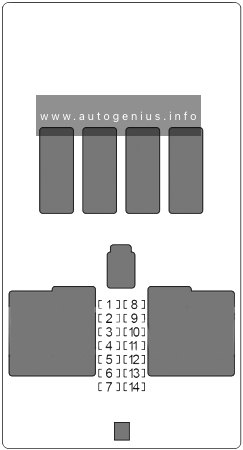
Body Domain Controller
| № | Amps | Protected Component |
|---|---|---|
| 1 | 30A | Passenger Power Window |
| 2 | 30A | Rear Driver’s Side Power Window |
| 3 | 20A | Front Passenger Door Lock |
| 4 | 30A | Driver Power Window |
| 5 | 30A | Rear Window Defogger |
| 6 | 30A | Rear Passenger Side Power Window |
| 7 | 20A | Driver’s Door Lock |
| 8 | – | – |
| 9 | 5A | Light Operating Unit, Steering Column Switch Cluster, Driver Assistance System Operating Facility with Hazard Warning Switch |
| 10 | 7.5A | Diagnosis Socket |
| 11 | 7.5A | Heating/Air Conditioning System, Tailgate Function Module |
| 12 | 5A | Evaluation Electronics for Contact-Free Tailgate Opening, Telematic Communication Box, Electronic Outer Door Handle Module (Driver/Passenger) |
| 13 | 15A | Horn |
| 14 | 15A | Rear Wiper & Washer |
Fusible Link Block
Fuse Box Diagram
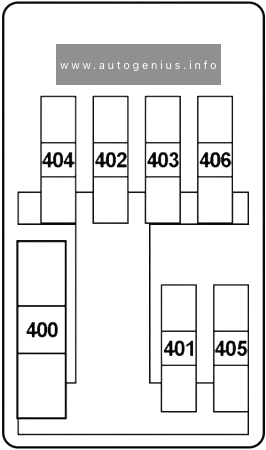
Assignment of the fuses in the glove box
| No. | A | Protected Component |
|---|---|---|
| 400 | 250 | Front Power Distribution Box |
| 401 | 60 | Fan →400W: Electric Fan Cut-Out Relay |
| 80 | Fan 600W: Electric Fan Cut-Out Relay | |
| 125 | Fan 850W: Electric Fan Cut-Out Relay | |
| 402 | 125 | Electromechanical Power Steering |
| 403 | 50 | →06.18: Dynamic Stability Control (DSC) |
| 60 | 07.18→: Dynamic Stability Control (DSC) | |
| 404 | 125 | Body Domain Controller |
| 405 | 100 | Front Electric Auxiliary Heater |
| 406 | 40 | Diesel: Fuel Filter Heating |
| 40 | Steptronic with Double Clutch: Twin-Clutch Gearbox Relay | |
| 60 | Control Electronics for Electric Auxiliary Heater in Engine Compartment |
WARNING: Terminal and harness assignments for individual connectors will vary depending on vehicle equipment level, model, and market.