Chevrolet Equinox (2009) – fuse and relay box diagram
Year of production: 2009
This article focuses on the first-generation Chevrolet Equinox, manufactured between 2005 and 2009. It includes fuse box diagrams for the 2009 models, details the locations of the fuse panels within the vehicle, and provides information on the function and layout of each fuse and relay.
Passenger compartment
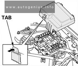
Fuse Box Location
The fuse box is located under the dashboard on the passenger’s side of the center console, behind the cover.
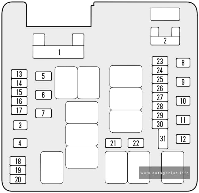
Fuse Box Diagram
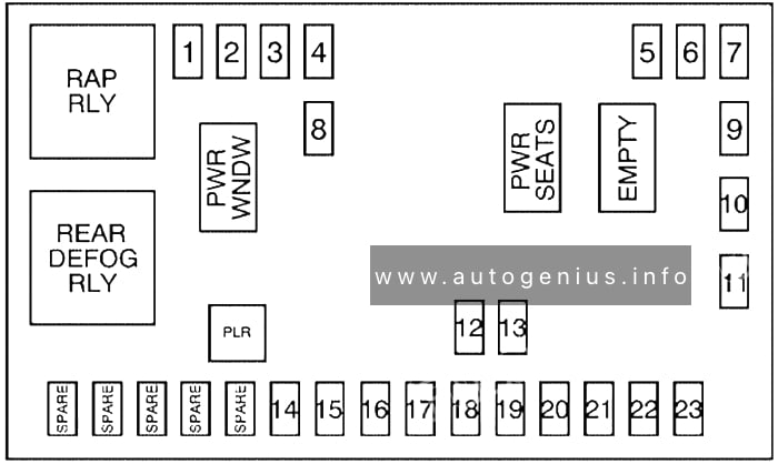
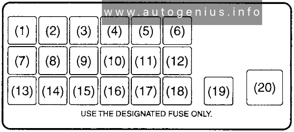
Chevrolet Equinox (2008) – fuses and relay box diagram – passenger compartment
Assignment of the fuses and relays in the passenger compartment
№
Description
1
Sunroof, Inside Rear View Mirror, Compass
2
Rear Seat Entertainment
3
Rear Wiper
4
Liftgate
5
Airbags
6
Heated Seats
7
Driver’s Side Turn Signal
8
Door Locks
9
Automatic Occupant Sensing Module
10
Power Mirrors
11
Passenger’s Side Turn Signal
12
Amplifier
13
Steering Wheel Illumination
14
Infotainment
15
Climate Control System, Remote Function Actuator
16
Canister Vent
17
Radio
18
Cluster
19
Ignition Switch
20
Body Control Module
21
Communications Integration Module
22
Center High-Mounted Stoplamp, Dimmer
23
Interior Lights
SPARE
Spare fuses
PWR WNDW
Power Windows (Circuit Breaker)
PWR SEATS
Power Seats (Circuit Breaker)
EMPTY
Empty (Circuit Breaker)
PLR
Fuse Puller
Relays
RAP RLY
Retained Accessory Power Relay
REAR DEFOG RLY
Rear Defogger Relay
Engine Compartment
Fuse Box Diagram
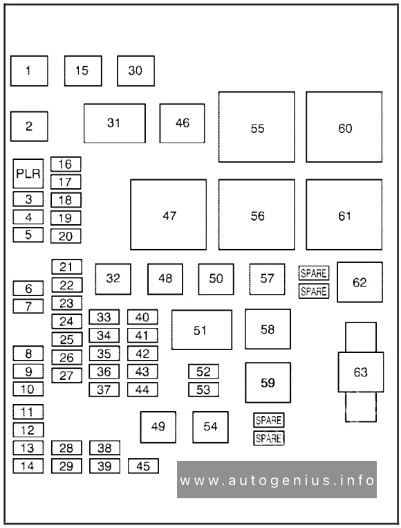
Chevrolet Equinox (2008) – fuses and relay box diagram – engine compartment
Assignment of the fuses and relays in the engine compartment
№
Description
1
Cooling Fan 2
2
Cooling Fan 1
3
Auxiliary Power
4
Rear HVAC
5
Spare
6
Sun Roof
7
Anti-lock Brake System
8
Air Conditioning Clutch
9
Driver’s Side Low-Beam
10
Daytime Running Lamp 2
11
Passenger’s Side High-Beam
12
Passenger’s Side Park Lamp
13
Horn
14
Driver’s Side Park Lamp
15
Starter
16
Electronic Throttle Control, Engine Control Module
17
Emission Device 1
18
Even Coils, Injectors
19
Odd Coils, Injectors
20
Emission Device 2
21
Spare
22
Powertrain Control Module, Ignition
23
Transmission
24
Mass Airflow Sensor
25
Airbag Display
26
Spare
27
Stoplamp
28
Passenger’s Side Low-Beam
29
Driver’s Side High-Beam
30
Battery Main 3
32
Spare
33
Engine Control Module, Battery
34
Transmission Control Module, Battery
35
Trailer Park Lamp
36
Front Wiper
37
Driver’s Side Trailer Stoplamp, Turn Signal
38
Spare
39
Fuel Pump
40
Not Used
41
All-Wheel Drive
42
Regulated Voltage Control
43
Passenger’s Side Trailer Stoplamp, Turn Signal
44
Spare
45
Front, Rear Washer
48
Rear Defogger
49
Anti-lock Brake System Motor
50
Battery Main 2
52
Daytime Running Lamps
53
Fog Lamps
54
Climate Control System Blower
57
Battery Main 1
63
Megafuse / Electric Power Steering
Relays
31
Ignition Main
46
Air Conditioning Compressor Clutch
47
Powertrain
51
Spare
55
Crank
56
Fan 1
58
Passenger’s Side Trailer Stoplamp, Turn Signal
59
Driver’s Side Trailer Stoplamp, Turn Signal
60
Fan 3
61
Fan 2
62
Fuel Pump
WARNING: Terminal and harness assignments for individual connectors will vary depending on vehicle equipment level, model, and market.
Volkswagen Polo (6R/MK5; 2009 – 2017) – fuse and relay box diagram
Year od production: 2009, 2010, 2011, 2012, 2013, 2014, 2015, 2016, 2017
This article focuses on the fifth-generation Volkswagen Polo (6R/6C/61), produced from 2009 to 2018. It includes fuse box diagrams for models from 2009 to 2017, provides information on the location of the fuse panels inside the vehicle, and details the fuse and relay assignments (fuse layout).
Passenger Compartment Fuse Box
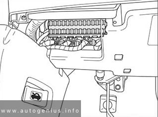
Fuse Box Location
The fuse box is located behind the cover below the steering wheel.
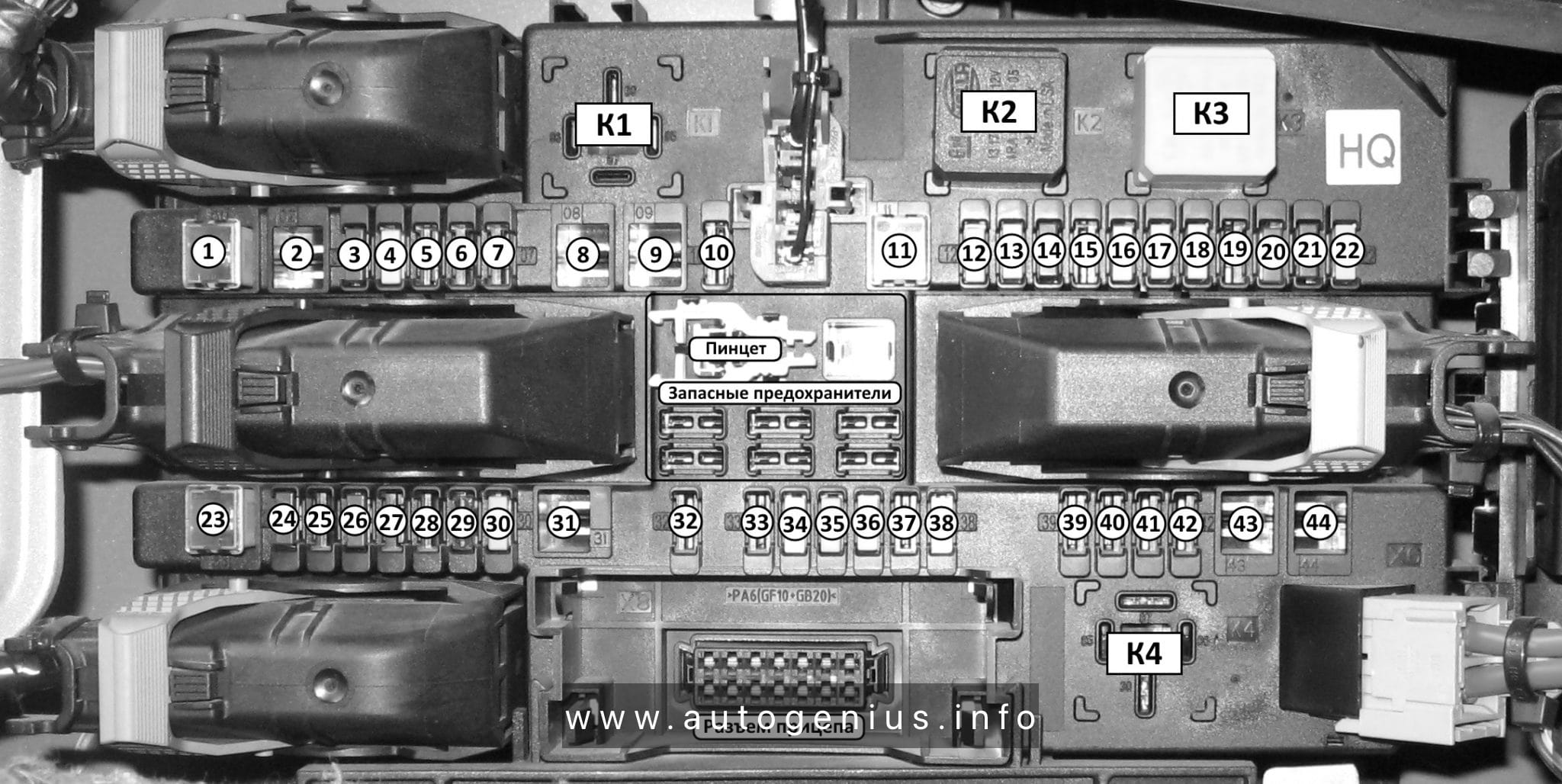
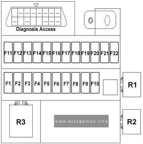
Fuse Box Diagram
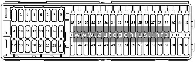
Volkswagen Polo (6R/MK5; 2009 – 2017) – fuses and relay box diagram – passenger compartment
Assignment of the fuses in the passenger compartment
№
Amp
Component
F1
5A
Control unit in dash panel insert
ABS control unit
Mobile telephone operating electronics control unit
F2
10A
Steering column combination switch
On-board supply control unit
Rear window wiper motor
Windscreen and rear window washer pump
F3
5A
Fuel pump relay
Engine control unit
Fuel supply relay
Fuel pump control unit
Control unit for structure-borne sound
F4
2A
(2A) Combination switch
F5
–
–
F6
5A
Instrumentation control module
F7
5A
Headlight range control regulator
Number plate left light
Number plate right light
On-board supply control unit
F8
10A
Engine management system
F9
5A/7.5A
TCS and ESP button
Tyre pressure monitor display button
Steering angle sender
ABS control unit
Stop/start system button
Data bus diagnostic interface
F10
5A
Cruise control system switch
Steering column combination switch
Brake light switch
Clutch pedal switch
On-hoard supply control unit
F11
5A/10A
Headlight range control regulator
Left headlight range control motor
Right headlight range control motor
Cruise control system switch
On-hoard supply control unit
Cornering light and headlight range control unit
F12
5A
Door mirror adjustment switch
F13
5A
Transmission control module (TCM)
F14
5A
Supplementary restraint system (SRS) control module
F15
5A
Heated windscreen waterjets
F16
5A
Parking aid control module
F17
–
–
F18
5A
Rear fog light cut-out contact switch
Control unit in dash panel insert
Rear left fog light bulb
On-board supply control unit
F19
5A
Multifunction control module
F20
5A
Steering angle sender
Control unit in dash panel insert
Fuel supply relay
Terminal 30 voltage supply relay
Low heat output relay
High heat output relay
F21
10A
Multifunction control module
F22
5A
Diagnostic connection
Climatronic control unit
Air conditioning system control unit
Mobile telephone operating electronics control unit
Ignition key withdrawal lock solenoid
F23
5A
Selector lever Rain sensor
On-hoard supply control unit
Engine control unit
Data bus diagnostic interface
F24
5A
On-board supply control unit
Driver side heated exterior mirror
Front passenger side heated exterior mirror
F25
5A
High pressure sender
Heater control unit
Radiator fan control unit
Air conditioning system control unit
Trailer detector control unit
Diagnostic connection
Humidity sender
Radiator fan control unit
Voltage stabiliser
Voltage stabiliser 2
F26
7,5A
Air mass meter
Oil level and oil temperature sender
Power steering control unit
Heater element for crankcase breather
Starter relay 1
Starter relay 2
F27
7,5A
Reversing lamps
F28
10A
Engine management system
F29
10A
Engine management system
F30
10A
Engine management system
F31
5A/10A
Engine management system
F32
10A/15A/20A/30A
Engine management system
F33
5A
Clutch position sender
Brake light switch
F34
15A
Control unit in dash panel insert
Left main beam bulb
Right main beam bulb
On-board supply control unit
Left gas discharge light control unit
Right gas discharge light control unit
F35
15A/20A
Engine management system
F36
7,5A
Right main beam bulb
F37
25A
Seat heater control module
F38
30A
Transmission control module (TCM)
F39
10A/15A
Right dipped beam bulb
F40
30A
AC/heater blower control module
F41
10A
Rear screen wiper motor
F42
15A
Cigarette lighter 12 V socket
F43
15A
Multifunction control module
F44
5A
Alarm system
F45
15A
Audio system
F46
20A
Head lamp washers
F47
20A
On-board supply control unit
Windscreen wiper motor
F48
25A
Multifunction control module
F49
15A/30A
Fuel pump relay
Fuel supply relay
F50
25A
Door function control module, driver
F51
25A
Door function control module, passenger
F52
30A
Rear left door control unit
Rear right door control unit
F53
30A
Multifunction control module
F54
15A
Front fog lamps
F55
15A/20A
Engine management system
F56
15A
Day time running lamps
F57
15A
Multifunction control module
F58
20A
Brake servo vacuum pump
F59
10A/15A
Left dipped beam bulb
F60
15A
Audio system
The onboard supply control unit
Fuse Box Location
The fuse/relay panel located on left underneath the dashboard.
Fuse Box Diagram
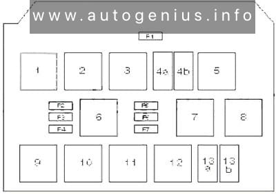
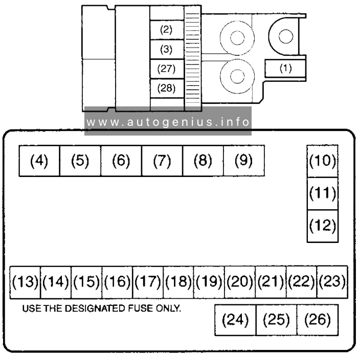
Volkswagen Polo (6R/MK5; 2009 – 2017) – fuses and relay box diagram – passenger compartment (onboard supply control unit)
Assignment of the fuses in the passenger compartment (onboard supply control unit)
№
Amp
Component
1
2
3
Ignition main circuits relay
4a
Headlamp low beam relay
4b
Fuel system primer relay
5
ABS protection relay
6
Petrol: Fuel pump (FP) relay
7
Starter motor inhibit relay
8
Ignition auxiliary circuits relay
9
Headlamp washer pump relay
10
Ignition auxiliary circuits relay (08.09)
11
12
13a
Starter motor relay
13b
Auxiliary heater relay
F1
30A
Sunroof control module
F2
40A
Engine coolant heater
F3
40A
Engine coolant heater
F4
40A
Engine coolant heater
F5
20A
Trailer control module
F6
20A
Trailer control module
F7
15A
Trailer control module
Engine Compartment Fuse Box
Fuse Box Location
It is located in the engine compartment on the battery.
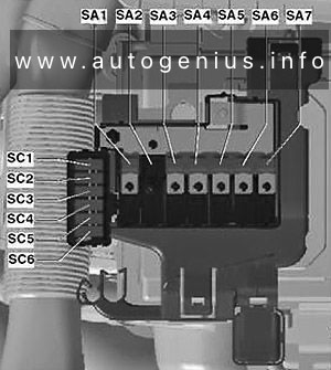
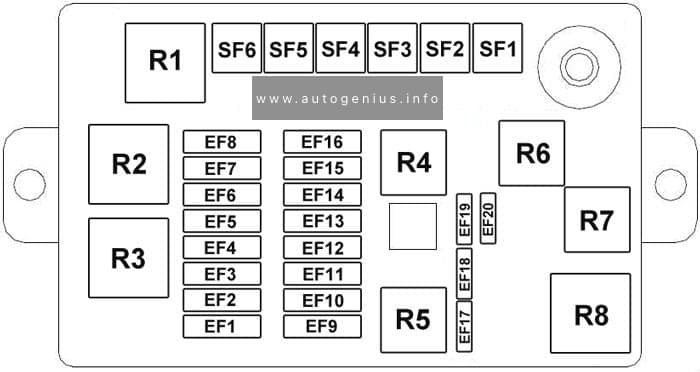
Fuse Box Diagram (Main fuse box)
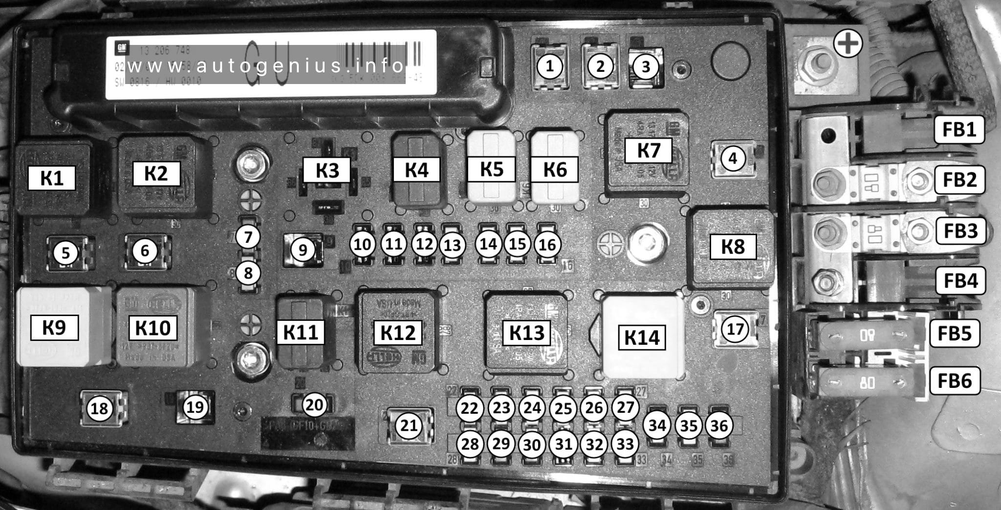
Volkswagen Polo (6R/MK5; 2009 – 2017) – fuses and relay box diagram – engine compartment (main fuse box)
Assignment of the fuses in the engine compartment (main fuse box)
№
Amp
Component
SA1
150A/175A
Alternator
SA2
30A
Gas fuel control module
SA3
110A
SA4
50A
Power steering control module
SA5
40A
ABS control module
SA6
40A
Engine coolant blower motor control module
SA7
50A
Glow plugs
SC1
25A
ABS control module
SC2
30A
Engine coolant blower motor control module
SC3
5A
Engine coolant blower motor control module
SC4
10A
ABS control module
SC5
5A
Multifunction control module
SC6
30A
Transmission control module (TCM)
WARNING: Terminal and harness assignments for individual connectors will vary depending on vehicle equipment level, model, and market.
This article covers the facelifted Mitsubishi Colt (Z30), produced from 2009 to 2012. It includes fuse box diagrams for the 2009, 2010, 2011, and 2012 models, provides information on the locations of the fuse panels within the vehicle, and details the function of each fuse and relay (fuse layout).
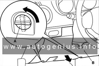
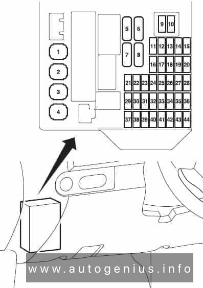
Passenger Compartment Fuse Box
Fuse Box Location
It is located behind the cover in front of the driver’s seat. Turn the clips (A) anticlockwise, then remove the cover (B).
Year of production: 2009, 2010, 2011, 2012, 2013, 2014
This article focuses on the seventh-generation Suzuki Alto, manufactured between 2009 and 2014. It includes fuse box diagrams for the 2009 to 2014 models, provides details on the location of the fuse panels within the vehicle, and explains the function of each fuse (fuse layout).
Passenger Compartment Fuse Box
Fuse Box Location
The fuse box is located under the driver’s side of the dashboard.
Vauxhall Astra H – (2004 – 2009) – fuse and relay box diagram
Year of production: 2004, 2005, 2006, 2007, 2008, 2009
The Opel Astra H, the third generation of the Opel Astra compact-class passenger car, was produced from 2004 to 2009 with both gasoline and diesel engine options. Also marketed as the Vauxhall Astra H, this model underwent a facelift during its production period. In this article, you will find information on the locations of the control units, detailed descriptions of the Astra H fuse boxes and relays, their diagrams. Additionally, we will identify the fuse responsible for the cigarette lighter.
Engine compartment fuse box
Insert a screwdriver into the opening as far as it will go and tilt it sideways. Open the cover upwards and remove. The fuse box has two different fuse assignments depending on the load compartment fuse box variant,
Fuse Box Diagram
Vauxhall Astra H (2004 – 2009) – fuse and relay diagram – engine compartment
Assignment of the fuses in the engine compartment.
Heating system, interior ventilation, climate control (HVAC)
F4
30A
Heating, ventilation and air conditioning (HVAC)
F5
30A or 40A
Radiator fan
F6
20A or 30A or 40A
Radiator fan
F7
10A
Windscreen washers (front and rear)
20A
(without REC) Central locking ZV
F8
15A
Horn
10
(without REC) Central locking ZV, Front windscreen washer, rear WA
F9
25A
Windscreen washers (front and rear)
25A
(without REC) Heated rear window HFH (K17_X125)
F10
7,5A
To the diagnostic connector DIAG
F11
7,5A
Instruments
F12
5A
Circulation pump
7,5A
(without REC) Inf. ID Display, Twin Audio TWA Audio System, DAB Digital Broadcasting, TCV Voice Control Phone
F13
15A
Fog lamp
5A
Interior lamp IRL (K18_X125)
F14
30A
Windscreen wiper (front)
F15
30A
Windscreen wiper (rear)
F16
5A
Engine control module / Open-Start / Stop system (without REC) ABS-ESP, Sound signal (K4_X125), Air conditioning, semi-automatic air conditioning, electronic climate control, Brake light switch, el. hydraulic rigid top
F17
25A
Fuel filter heating (diesel models)
F18
25A
Starter
F19
30A
Electronic gearbox equipment
F20
10A
Air conditioner compressor, Horn (K4_X125)
F21
20A
Engine control module (ECM)
F22
7.5A
Engine control module (ECM)
F23
10A
Adaptive headlight system (AFL), headlamp leveling
F24
15A
Fuel pump
F25
15A
Electronic gearbox equipment
F26
10A
Engine control module (ECM)
F27
5A
Power steering
F28
5A
Electronic equipment of a transmission
F29
7.5A
Electronic equipment of gearbox
7.5A
(with REC) Control unit gearbox Automatic / Easytronic
F30
10A
Engine control module (ECM)
F31
10A
Adaptive headlight system (AFL). Headlamp leveling
15A
(without REC) Rear window wiper (K56)
F32
5A
Brake system fault indicator lamp, air conditioning, clutch pedal switch
F33
5A
Headlight leveling, Adaptive Forward Lighting (AFL), Outdoor light control unit
F34
7.5A
Steering column module control unit
F35
20A
Infotainment system
F36
7.5A
Mobile phone, digital radio receiver, Twin Audio system, multifunction display
Opel Astra H – (2004 – 2009) – fuse and relay box diagram
Year of production: 2004, 2005, 2006, 2007, 2008, 2009
The Opel Astra H, the third generation of the Opel Astra compact-class passenger car, was produced from 2004 to 2009 with both gasoline and diesel engine options. Also marketed as the Vauxhall Astra H, this model underwent a facelift during its production period. In this article, you will find information on the locations of the control units, detailed descriptions of the Astra H fuse boxes and relays, their diagrams. Additionally, we will identify the fuse responsible for the cigarette lighter.
Engine compartment fuse box
Insert a screwdriver into the opening as far as it will go and tilt it sideways. Open the cover upwards and remove. The fuse box has two different fuse assignments depending on the load compartment fuse box variant,
Fuse Box Diagram
Opel Astra H (2004 – 2009) – fuse and relay diagram – engine compartment
Assignment of the fuses in the engine compartment.
Heating system, interior ventilation, climate control (HVAC)
F4
30A
Heating, ventilation and air conditioning (HVAC)
F5
30A or 40A
Radiator fan
F6
20A or 30A or 40A
Radiator fan
F7
10A
Windscreen washers (front and rear)
20A
(without REC) Central locking ZV
F8
15A
Horn
10
(without REC) Central locking ZV, Front windscreen washer, rear WA
F9
25A
Windscreen washers (front and rear)
25A
(without REC) Heated rear window HFH (K17_X125)
F10
7,5A
To the diagnostic connector DIAG
F11
7,5A
Instruments
F12
5A
Circulation pump
7,5A
(without REC) Inf. ID Display, Twin Audio TWA Audio System, DAB Digital Broadcasting, TCV Voice Control Phone
F13
15A
Fog lamp
5A
Interior lamp IRL (K18_X125)
F14
30A
Windscreen wiper (front)
F15
30A
Windscreen wiper (rear)
F16
5A
Engine control module / Open-Start / Stop system (without REC) ABS-ESP, Sound signal (K4_X125), Air conditioning, semi-automatic air conditioning, electronic climate control, Brake light switch, el. hydraulic rigid top
F17
25A
Fuel filter heating (diesel models)
F18
25A
Starter
F19
30A
Electronic gearbox equipment
F20
10A
Air conditioner compressor, Horn (K4_X125)
F21
20A
Engine control module (ECM)
F22
7.5A
Engine control module (ECM)
F23
10A
Adaptive headlight system (AFL), headlamp leveling
F24
15A
Fuel pump
F25
15A
Electronic gearbox equipment
F26
10A
Engine control module (ECM)
F27
5A
Power steering
F28
5A
Electronic equipment of a transmission
F29
7.5A
Electronic equipment of gearbox
7.5A
(with REC) Control unit gearbox Automatic / Easytronic
F30
10A
Engine control module (ECM)
F31
10A
Adaptive headlight system (AFL). Headlamp leveling
15A
(without REC) Rear window wiper (K56)
F32
5A
Brake system fault indicator lamp, air conditioning, clutch pedal switch
F33
5A
Headlight leveling, Adaptive Forward Lighting (AFL), Outdoor light control unit
F34
7.5A
Steering column module control unit
F35
20A
Infotainment system
F36
7.5A
Mobile phone, digital radio receiver, Twin Audio system, multifunction display
The Honda FR-V (also known as the Edix), a compact MPV, was manufactured from 2004 to 2009. This article includes fuse box diagrams for the 2005, 2006, 2007, 2008, and 2009 models, provides details on the locations of the fuse panels within the vehicle, and explains the function of each fuse (fuse layout).
Passenger Compartment Fuse Box
Fuse Box Location
The interior fuse box is under the dashboard on the driver’s side.
Toyota Previa (2009 – 2012) – fuse and relay box diagram
Year of production: 2009, 2010, 2011, 2011, 2012
The Toyota Previa is a versatile and spacious minivan, also known as an MPV (multi-purpose vehicle), that has been sold globally under different names. In some markets, like Australia, it was sold as the Toyota Tarago, while in others it retained the Previa name. It is renowned for its futuristic design, reliability, and practical features, making it a popular choice for families and commercial users alike.
Key Features of the Toyota Previa:
1.Unique Design: The Previa had a distinctive egg-shaped design, especially in its earlier generations, which made it stand out among other minivans. The rounded aerodynamic body contributed to better fuel efficiency and reduced drag.
2.Seating Capacity: Depending on the market and configuration, the Previa typically offered seating for 7 to 8 passengers, making it a spacious option for families.
3.Mid-Engine Layout: One of the most unique aspects of the first-generation Previa was its mid-engine design. The engine was located under the front seats, which allowed for better weight distribution but made maintenance slightly more challenging.
4.All-Wheel Drive (AWD): Some versions of the Previa were available with all-wheel drive, enhancing traction and making it suitable for a variety of driving conditions, including rough terrain or snow.
5.Sliding Doors: The Previa featured sliding rear doors for easier passenger entry and exit, especially in tight parking spaces.
6.Flexible Interior: With foldable or removable rear seats, the Previa was designed to offer flexible space for both passengers and cargo.
Generations:
1.First Generation (1990–1999):
•This model had a very unconventional design with a mid-engine layout. The engine was mounted underneath the front seats, and it featured rear-wheel drive or optional all-wheel drive.
•Engine options included a 2.4-liter inline-4 engine and later models offered supercharged variants for more power.
•The Previa was known for its durability and spacious interior, despite its somewhat unconventional engine placement.
2.Second Generation (2000–2006):
•The second-generation Previa featured a more traditional front-engine, front-wheel-drive layout.
•It was available with a range of engines, including more fuel-efficient options. In some markets, it came with a V6 engine.
•The design was more streamlined and modern, with improved safety features and more advanced technology in the interior.
•Toyota focused on comfort and refinement, making it more family-friendly.
3.Third Generation (2006–2019):
•This generation offered even more refinement in terms of luxury, technology, and performance.
•It came with advanced features like dual-zone climate control, premium audio systems, and even hybrid variants in some regions.
•By this generation, the Previa was primarily marketed in Asia, while markets like North America received the Toyota Sienna as the main minivan option.
Previa Hybrid:
In the later years, Toyota introduced a hybrid version of the Previa, particularly in the Asian markets. It featured Toyota’s Hybrid Synergy Drive, combining a gasoline engine with an electric motor to improve fuel efficiency, making it an eco-friendlier option for larger families.
Successors:
In many regions, the Toyota Previa was phased out or replaced by other models, such as the Toyota Alphard, Toyota Estima, or the Toyota Sienna (in North America). Despite this, the Previa remains a memorable model due to its distinctive design and practicality.
The Previa is still favored in the used car market for those looking for a reliable, spacious vehicle with Toyota’s legendary durability.
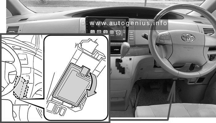
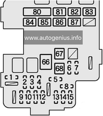
Instrument Panel Fuse Box №1 (left side)
Fuse Box Location
Remove the cover; Remove the lid.
Toyota Previa (2009 – 2012) – fuse and relay box location – passenger compartment fuse box no. 1
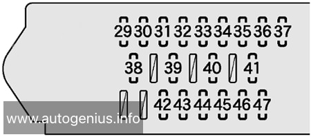
Fuse Box Diagram
Toyota Previa (2009 – 2012) – fuse and relay box diagram – passenger compartment fuse box no. 1
Assignment of the fuses in the Fuse Box №1
№
Name
Amp
Description
29
WELCAB
30A
No circuit
30
4WD
7.5A
No circuit
31
AC INV
15A
No circuit
32
DR LOCK
30A
Multiplex communication system
33
P/W FL
20A
Power windows
34
S/R
20A
Rear sunshade
35
PSD LH
30A
Power slide door
36
P/W RL
20A
Power windows
37
PBD
30A
No circuit
38
RR WIP
15A
Windshield wipers and washer, rear window wiper and washer, headlight cleaner
39
GAUGE №1
10A
Anti-lock brake system, vehicle stability control system, adaptive front lighting system, electric cooling fan, Toyota parking assist system, headlight cleaner
40
PANEL
10A
Instrument panel lights, Toyota parking assist system
41
TAIL
10A
Front fog lights, tail lights, position lights, license plate lights
42
LH ECU-IG
10A
Adaptive front lighting system, multiplex communication system, power rear seat, power slide door
43
SEAT HTR LH
10A
Seat heater LH
44
GAUGE №2
10A
Charging system, automatic transmission system, backup lights, Toyota parking assist system
45
STP RR
7.5A
No circuit
46
STP HI MT
7.5A
No circuit
47
STP RL
7.5A
No circuit
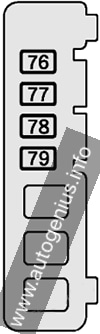
Instrument Panel Fuse Box №2 (right side)
Fuse Box Location
Remove the lid.
Toyota Previa (2009 – 2012) – fuse and relay box location – passenger compartment fuse box no. 2
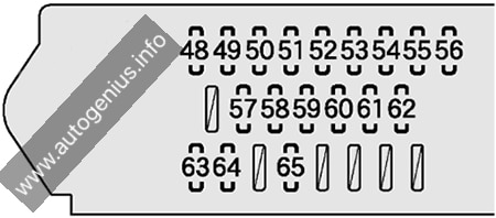
Fuse Box Diagram
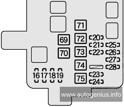
Toyota Previa (2009 – 2012) – fuse and relay box diagram – passenger compartment fuse box no. 2
Assignment of the fuses in the Fuse Box №2
№
Name
Amp
Description
48
PSB
30A
No circuit
49
RR FOG
7.5A
No circuit
50
P/W FR
20A
Power windows
51
P/SEAT RH
30A
Power seat
52
AM1
7.5A
Starting system
53
STOP
15A
Stop lights, high mounted stoplight, automatic transmission system, shift lock control system, multiport fuel injection system / sequential multi-port fuel injection system, anti-lock brake system, vehicle stability control system
54
OBD
7.5A
On-board diagnosis system
55
PSD RH
30A
Power slide door
56
P/W RR
20A
Power windows
57
P/POINT
15A
Power outlet
58
CIG
15A
Cigarette lighter
59
RAD №2
7.5A
Audio system, rear seat entertainment system
60
ECU-ACC
7.5A
Power rear view mirrors, shift lock system
61
IGN
10A
Multiport fuel injection system / sequential multiport fuel injection system, SRS airbag system, multiplex communication system
62
MET
7.5A
Gauges and meters
63
FR WIP
30A
Windshield wipers and washer
64
SEAT HTR RH
10A
Seat heater RH
65
RH ECU-IG
10A
Vehicle stability control system, air conditioning system, Toyota parking assist system, automatic transmission system, electric power steering system, power slide door, rear power sunshade, shift lock system, turn signal flashers, emergency flashers, vanity lights, multiplex communication system
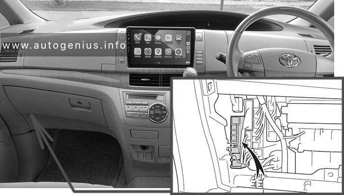
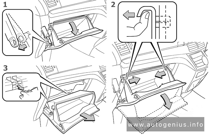
Instrument Panel Fuse Box №3
Fuse Box Location
Remove the lid.
Toyota Previa (2009 – 2012) – fuse and relay box location – passenger compartment fuse box no. 3
To access:
Open the glove box. Slide off the damper.
Pull both side of the glove box from the inside to disconnect the upper claws.
Pull out the glove box and disconnect the lower claws.
Toyota Previa (2009 – 2012) – fuse and relay box location – passenger compartment fuse box no. 3