Volkswagen UP! (2011 – 2017) – fuse and relay box diagram
Year of production: 2011, 2012, 2013, 2014, 2015, 2016, 2017
The city car Volkswagen Up is available from 2011 to the present. In this article, you will find fuse box diagrams of Volkswagen Up 2011, 2012, 2013, 2014, 2015, 2016 and 2017, get information about the location of the fuse panels inside the car, and learn about the assignment of each fuse (fuse layout).
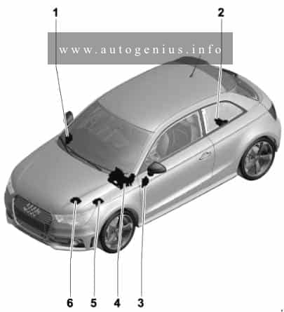
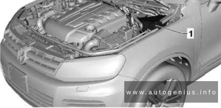
Location
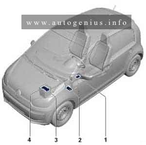
- Fuse holder D -SD-
- Fuse holder C -SC-
- Fuse holder B -SB-
- Fuse holder A -SA-
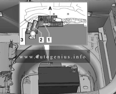
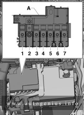
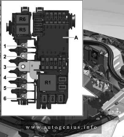
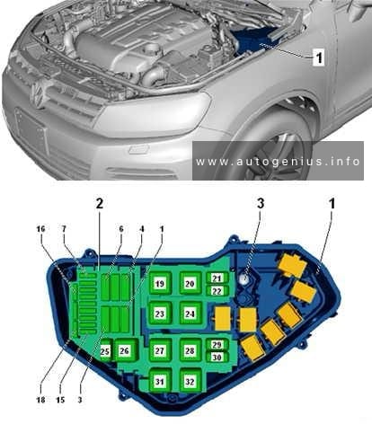
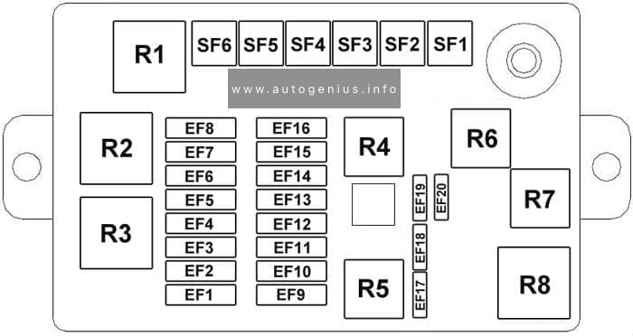
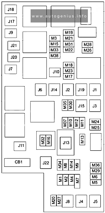
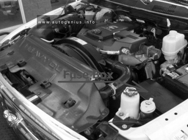
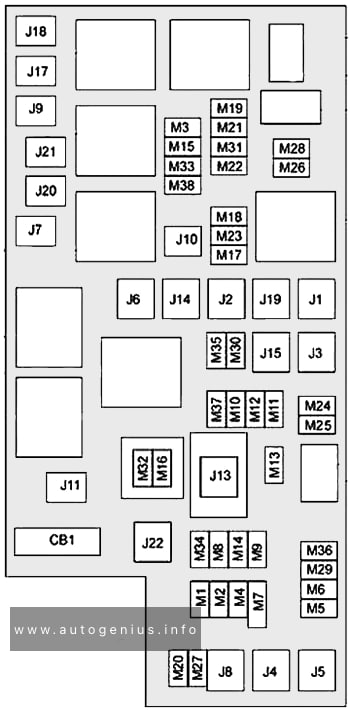
Engine compartment
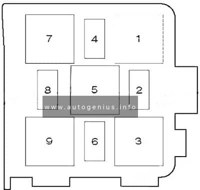
Fitting location fuse holder A -SA-
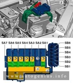
Assignment of the fuses in the engine compartment (holder A -SA-)
| № | A | Function/component |
| SA1 | 150 175*2 |
Alternator -C- |
| SA2 | 30 | Amplifier -R12- |
| SA3 | 110 | Fuse holder C -SC- Main relay -J271- Terminal 75 voltage supply relay 1 -J680- |
| SA4 | 40 50*3 |
Power steering control unit -J500- |
| SA5 | 40 | ABS control unit -J104- |
| SA6 | 40 | Radiator fan control unit -J293- |
| SA7 | 50 | Automated manual gearbox control unit -J514-*1 |
| 1 – Depends on equipment 2 – Only models with start/stop system 3 – From model May 2013 |
||
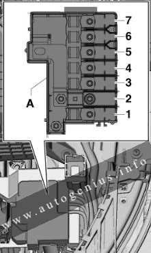
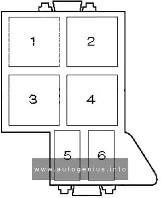
Fitting location fuse holder B -SB-
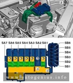
Assignment of the fuses in the engine compartment (holder B -SB-)
| № |
A |
Function/component |
| SB1 | 25 | ABS control unit -J104- |
| SB2 | 30 | Radiator fan thermal switch -F18- Radiator fan control unit -J293- |
| SB3 | 5 7.5*1 |
Radiator fan control unit -J293- Terminal S ignition/starter switch -D- |
| SB4 | 10 | ABS control unit -J104- |
| SB5 | 5 7.5*1 |
Onboard supply control unit -J519- |
| SB6 | 30 | Fuse holder C -SC- Ignition/starter switch -D- |
| 1 – From model May 2013 | ||
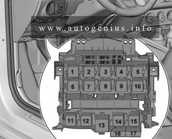
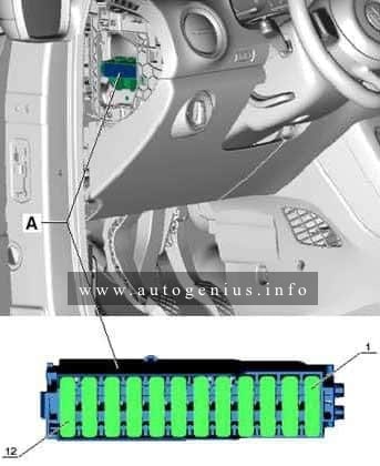
Passenger Compartment
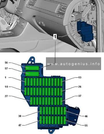
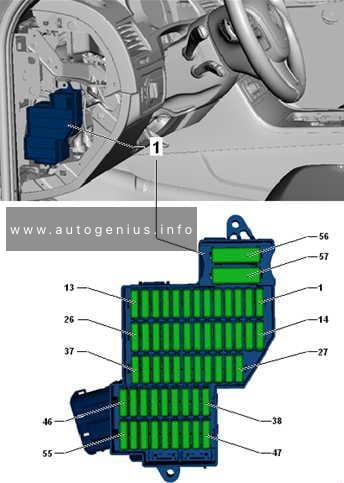
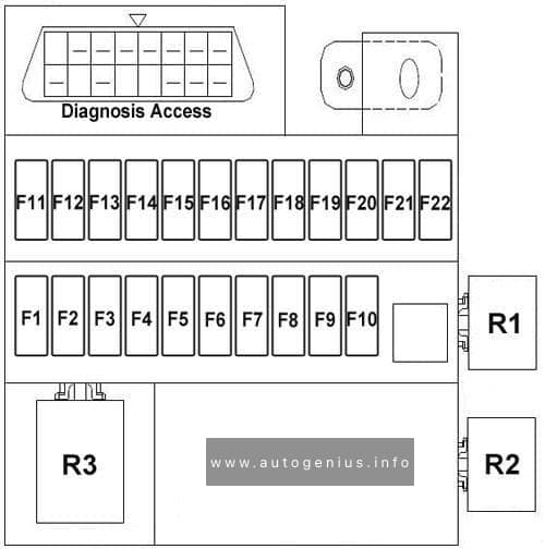
Fuse holder C -SC-
Assignment of the fuses in the passenger compartment (holder C -SC-)
| № |
A | Function/component |
| 1 | 5 7.5*1 |
Dash panel insert -K- Engine control unit -J623- Radiator fan control unit -J293- |
| 2 | 15 | Air conditioning system relay -J32- Air conditioning system control unit -J301- Diagnostic connection -U31- High-pressure sender -G65- |
| 3 | 7.5 | Brake light switch -F- Clutch pedal switch -F36- Camshaft control valve 1 -N205- |
| 4 | 7.5 | Onboard supply control unit -J519- • Light switch -E1- Dipped beam/daytime running lights/main beam |
| 5 | 5 7.5*1 |
Onboard supply control unit -J519- • Ignition/starter switch -D- CCS switch -E45- |
| 6 | 5 7.5*1 |
Headlight range control regulator -E102- Left headlight range control motor -V48- Right headlight range control motor -V49- Mirror adjustment switch -E43- |
| 7 | 10 | Selector lever -E313- |
| 8 | 7.5 | Automated manual gearbox control unit -J514- Selector lever -E313- |
| 9 | 7.5 | Airbag control unit -J234- Centre switch module 2 in dash panel -EX35- |
| 10 | 5 7.5*1 |
Parking aid control unit -J446- |
| 11 | 10 | Right headlight dipped beam bulb -M31- |
| 12 | 5 7.5*1 |
Dash panel insert -K- Rear left fog light bulb -L46- Control unit in dash panel insert -J285-*1 Onboard supply control unit -J519-*1 |
| 13 | 10 | Left headlight dipped beam bulb -M29- |
| 14 | 15 | Rear window wiper motor -V12- |
| 15 | 15 | Light switch -E1- |
| 16 | 5 7.5*1 |
Terminal 15 voltage supply relay -J329- Power steering control unit -J500- |
| 17 | 15 | Washer pump switch (automatic wash/wipe and headlight washer system) -E44- |
| 18 | 7.5 | Reversing light switch -F4- |
| 19 | 15 | Injector, cylinder 1 -N30- Injector, cylinder 2 -N31- Injector, cylinder 3 -N32- |
| 20 | 5 7.5*1 |
ABS control unit -J104- Emergency braking function sensor unit -J939- Steering angle sender -G85- |
| 21 | 5 7.5*1 |
Right side light bulb -M3- Right tail light bulb -M2- Number plate light -X- Onboard supply control unit -J519- • Light switch -E1- Side lights |
| 22 | 10 | Left daytime running light bulb -L174- Right daytime running light bulb -L175- |
| 23 | 5 7.5*1 |
Left side light bulb -M1- Left tail light bulb -M4- |
| 24 | 15 | Headlight flasher switch -E5- |
| 25 | 10 | Windscreen and rear window washer pump -V59- |
| 26 | 5 7.5*1 |
Main relay -J271- Dash panel insert -K- Steering angle sender -G85- |
| 27 | 7.5 | Onboard supply control unit -J519- • Front interior light -W1- • Front passenger reading light -W13- • Driver side reading light -W19- |
| 28 | 5 7.5*1 |
Diagnostic connection -U31- |
| 29 | 7.5 | Onboard supply control unit -J519- |
| 30 | 5 7.5*1 |
Onboard supply control unit -J519- • Heated exterior mirror on driver side -Z4- • Heated exterior mirror on front passenger side -Z5- |
| 31 | 10 | Lambda probe -G39- Lambda probe after catalytic converter -G130- Activated charcoal filter solenoid valve 1 -N80- |
| 32 | 15 | Onboard supply control unit -J519- • Turn signal/brake light |
| 33 | 10 | Right headlight main beam bulb -M32- |
| 34 | 10 | Left headlight main beam bulb -M30- Dash panel insert -K- |
| 35 | – | – |
| 36 | 15 20*1 |
Cigarette lighter -U1- |
| 37 | 30 | Air conditioning system control unit -J301- Heater control unit -J162- |
| 38 | 15 | Radio -R- |
| 39 | 30 | Sliding sunroof adjustment control unit -J245- |
| 40 | 15 | Engine control unit -J623- |
| 41 | 25 | Onboard supply control unit -J519- • Central locking |
| 42 | 25 | Ignition coil 1 with output stage -N70- Ignition coil 2 with output stage -N127- Ignition coil 3 with output stage -N291- |
| 43 | 20 | Heated front seats control unit -J774- Switch module in centre of dash panel -EX22- Centre switch module 2 in dash panel -EX35- |
| 44 | 15 | Fuel pump relay -J17- |
| 45 | 20 | Light switch -E1- |
| 46 | 30 | Onboard supply control unit -J519- • Heated rear window -Z1- |
| 47 | 25 30*1 |
Front right window regulator switch -E41- Operating unit for window regulator in driver door -E512-*4 Driver side central locking lock unit -F220-*3 |
| 48 | 20 | Onboard supply control unit -J519- • Treble horn -H2- • Bass horn -H7- |
| 49 | 20 30*1 |
Onboard supply control unit -J519- • Wiper motor control unit -J400- |
| 50 | 15 20*2 |
Left fog light bulb -L22- Right fog light bulb -L23- Onboard supply control unit -J519-*2 |
| 51 | 25 30*1,4 |
Front left window regulator switch -E40- Operating unit for window regulator in driver door -E512-*3 Driver side central locking lock unit -F220-*4 |
| 1 – From model May 2013 2 – Only models with start/stop system 3 – From model November 2014 4 – Only right-hand drive models |
||
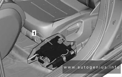
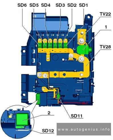
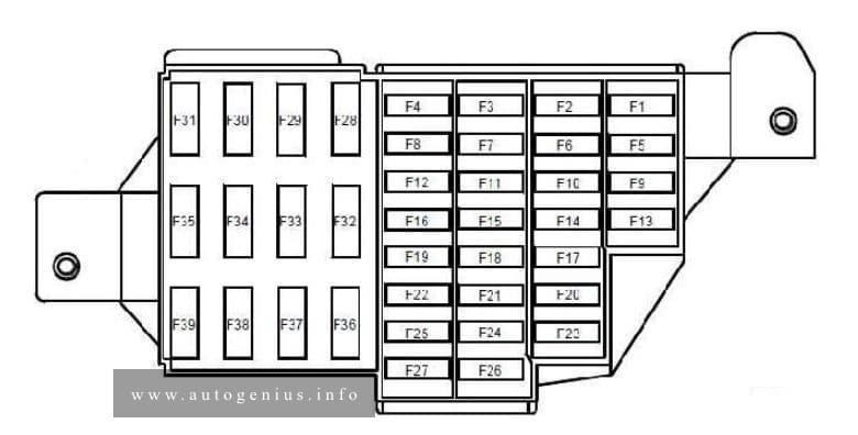
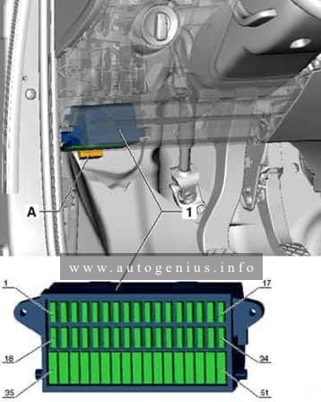
Fuse holder D -SD-
Assignment of the fuses in the passenger compartment (holder D -SD-)
| № |
A | Function/component |
| SD1 | 5 7.5*1 |
Emergency braking function sensor unit -J939- Relay for emergency braking function -J1020-*1 |
| SD2 | 5 7.5*1 |
Dash panel insert -K- |
| SD3 | 10 15*1 |
Radio -R- |
| SD4 | 7.5 | Voltage converter -A19- Starter relay 1 -J906- Starter relay 2 -J907- |
| SD5 | – | – |
| SD6 | – | – |
| SD7 | – | – |
| SD8 | – | – |
| SD9 | 15 | Onboard supply control unit -J519- • Right main beam/dipped beam/daytime driving lights |
| SD10 | 15 | Onboard supply control unit -J519- • Left main beam/dipped beam/daytime driving lights |
| SD11 | 30 | Starter relay 1 -J906- Starter relay 2 -J907- |
| SD12 | 30 | Voltage converter -A19- |
| 1 – From model May 2013 | ||
WARNING: Terminal and harness assignments for individual connectors will vary depending on vehicle equipment level, model, and market.