Chevrolet Cruze (J300; 2008 – 2016) – fuse and relay box diagram
Year of production: 2008, 2009, 2010, 2011, 2012, 2013, 2014, 2015, 2016
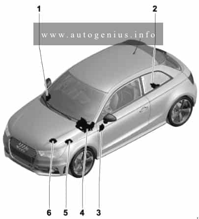
This article focuses on the first-generation Chevrolet Cruze (J300), manufactured between 2008 and 2016. It includes fuse box diagrams for the 2008 to 2016 models, provides details on the locations of the fuse panels inside the vehicle, and explains the function and layout of each fuse and relay.
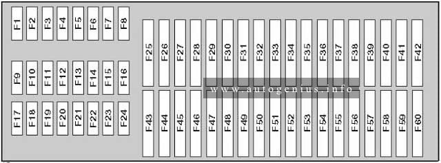
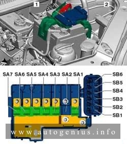
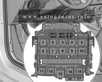
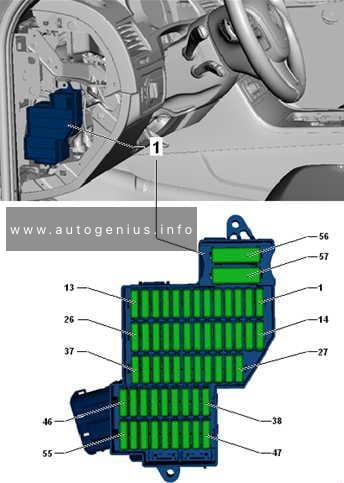
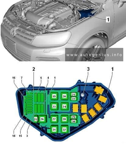
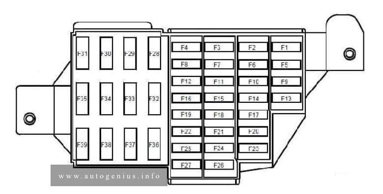
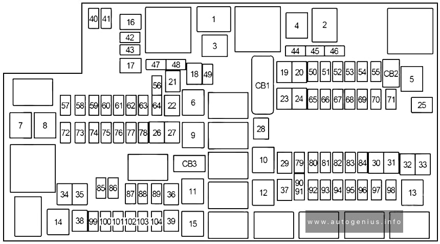
Engine compartment fuse box
Fuse box diagram
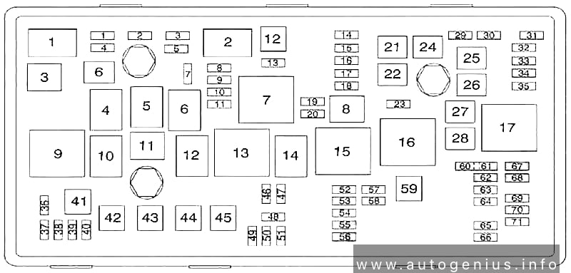
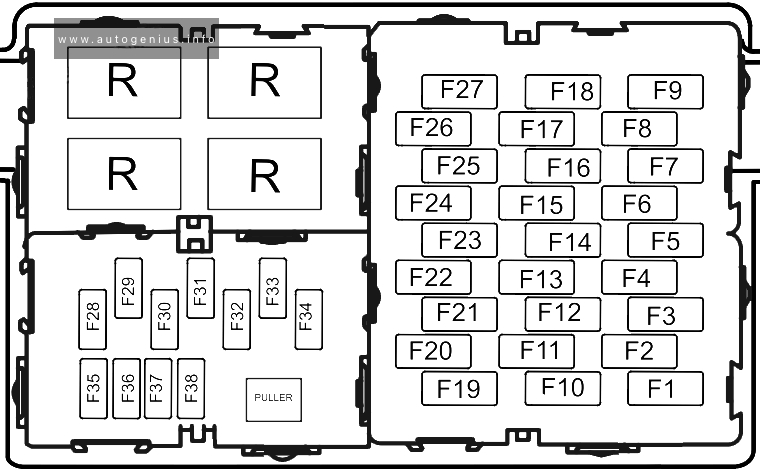
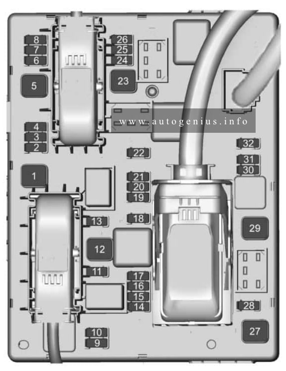
Assignment of the fuses and relay in the engine compartment
| No. |
A |
Description |
| 1 | 15 | Transmission Control Module |
| 2 | 15 | Engine Control Module |
| 3 | N/A | Not Used |
| 5 | 15 | Transmission Control Module, Engine Control Module, Mass Air Flow/Intake Air Temperature Sensor, Output Speed Sensor |
| 6 | 30 | Windshield Wiper Relays |
| 7 | N/A | Not Used |
| 8 | 15 | Fuel injectors |
| 9 | 15 | Ignition Coil, Fuel Injectors |
| 10 | 15 | Engine Control Module, Output Speed Sensor |
| 11 | 10 | Heated Oxygen Sensors |
| 12 | 30 | Starter Motor |
| 13 | 7.5 | Evaporative Emission (EVAP) Canister Vent Solenoid Valve |
| 14 | N/A | Not Used |
| 15 | N/A | Not Used |
| 16 | 7.5 | Air Quality Sensor |
| 17 | 5 | Inflatable Restraint Sensing and Diagnostic Module |
| 18 | 10 | Fuel Pump Control Module |
| 19 | N/A | Not Used |
| 20 | 20 | Fuel Pump Relay |
| 21 | 30 | Windows Motors, Front Door |
| 22 | N/A | Not Used |
| 23 | N/A | Not Used |
| 24 | 30 | Windows Motors, Front Door |
| 25 | N/A | Not Used |
| 26 | 40 | Electronic Brake Control Module (EBCM) |
| 27 | 30 | Remote Control Door Lock Receiver |
| 28 | 40 | Rear Demister Grid |
| 29 | N/A | Not Used |
| 30 | 15 | Electronic Brake Control Module (EBCM) |
| 31 | 20 | Body Control Module |
| 32 | 20 | Body Control Module |
| 33 | 30 | Heated Seat Control Module |
| 34 | 25 | Sunroof Control Module |
| 35 | 30 | Audio Amplifier |
| 36 | N/A | Not Used |
| 37 | 10 | Headlamp – Right Main beam |
| 38 | 10 | Headlamp – Left Main beam |
| 39 | N/A | Not Used |
| 40 | N/A | Not Used |
| 41 | N/A | Not Used |
| 42 | 20/30 | Cooling Fan Relays, Cooling Fan Motor |
| 43 | N/A | Not Used |
| 44 | N/A | Not Used |
| 45 | 30/40 | Cooling Fan High Speed Relay, Cooling Fan Motor |
| 46 | 10 | Cooling Fan Relays |
| 47 | 10 | Heated Oxygen Sensors, Throttle Body |
| 48 | 15 | Fog Lights, Front |
| 49 | N/A | Not Used |
| 50 | N/A | Not Used |
| 51 | 15 | Horn |
| 52 | 5 | Instrument Cluster |
| 53 | 10 | Inside Rearview Mirror |
| 54 | 5 | Headlamp Switch, Electrical Auxiliary Heater, HVAC Control Module |
| 55 | 7.5 | Window Switches, Front, Mirror Switch |
| 56 | 15 | Windscreen Washer Pump |
| 57 | 15 | Steering Column Lock Control Module |
| 58 | N/A | Not Used |
| 59 | 30 | Fuel Heater |
| 60 | 7.5 | Outside Rearview Mirrors |
| 61 | N/A | Not Used |
| 62 | 10 | A/C Compressor Clutch Relay, A/C Compressor Clutch |
| 63 | N/A | Not Used |
| 64 | 5 | Inflatable Restraint Sensing and Diagnostic Module |
| 65 | N/A | Not Used |
| 66 | N/A | Not Used |
| 67 | 20 | Fuel Pump Control Module |
| 68 | N/A | Not Used |
| 69 | 5 | Body Control Module |
| 70 | 5 | Rain Sensor |
| 71 | N/A | Not Used |
| Relays | ||
| 1 | A/C Compressor Clutch | |
| 2 | Starter | |
| 3 | Cooling Fan | |
| 4 | Windshield Wiper Speed Control | |
| 5 | Windshield Wiper | |
| 6 | Not Used | |
| 7 | Powertrain | |
| 8 | Fuel Pump | |
| 9 | Cooling Fan Medium Speed 1 | |
| 10 | Cooling Fan Medium Speed 2 | |
| 11 | Not Used | |
| 12 | Cooling Fan Speed Control (Or in Relay Block – Under-bonnet) | |
| 13 | Cooling Fan High Speed Relay | |
| 14 | Not Used | |
| 15 | Ignition Main Relay | |
| 16 | Fuel Heater Relay | |
| 17 | Rear Window Defogger | |
| Note: Relays listed below are non-serviceable Printed Circuit Board (PCB) relays and are internal to the block. | ||
| – | Horn Relay | |
| – | Windscreen Washer Pump Relay | |
| – | Front Fog Lamp Relay | |
| – | Headlamp High Beam Relay | |
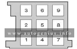
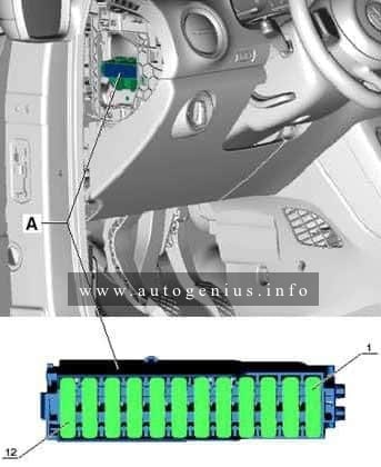
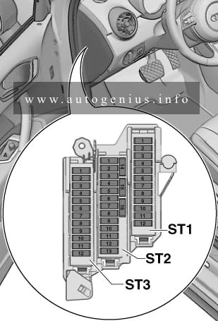
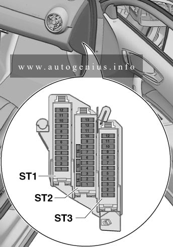
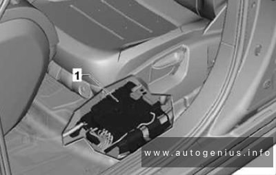
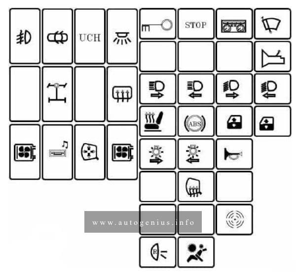
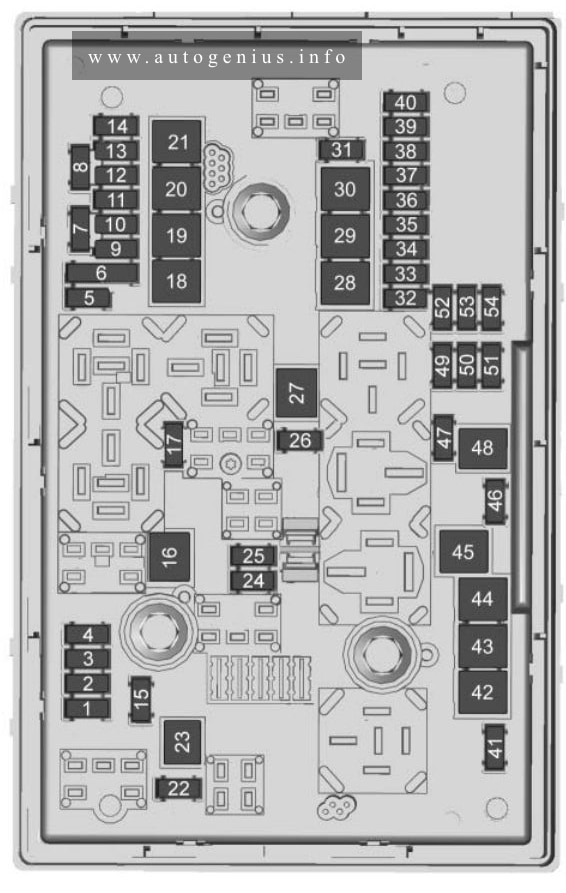
Instrument Panel Fuse Block
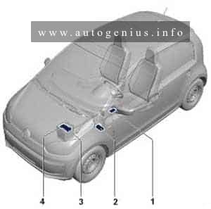
Fuse Box Location
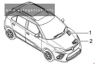
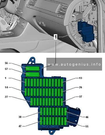
It is located in the instrument panel (on the driver’s side), behind under the cover to the left of the steering wheel.
Fuse box diagram
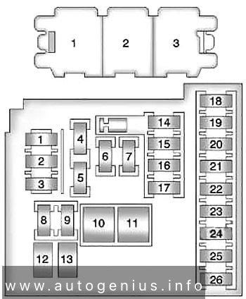
Assignment of the fuses and relay in the instrument panel
| No. |
A |
Description |
| 1 | 10 | Mobile Telephone Control Module |
| 2 | N/A | Not Used |
| 3 | 25 | Body Control Module |
| 4 | 20 | Radio |
| 5 | 7.5 | Parking Assist Control Module, Power Sounder, Multifunction Switch – Centre Console, Display |
| 6 | 20 | Cigar Lighter – Front |
| 7 | 20 | Accessory Power Outlet – Centre Console 1/2 |
| 8 | 30 | Body Control Module |
| 9 | 30 | Body Control Module |
| 10 | 30 | Body Control Module |
| 11 | 40 | Blower Motor Control Module |
| 12 | N/A | Not Used |
| 13 | 25 | Heated Seat Control Module |
| 14 | 7.5 | Data Link Connector, Oil Feeding Connector |
| 15 | 10 | Inflatable Restraint Sensing and Diagnostic Module |
| 16 | 10 | Rear Compartment Lid Release Relay |
| 17 | 15 | HVAC Control Module / HVAC Control Assembly |
| 18 | N/A | Not Used |
| 19 | N/A | Not Used |
| 20 | N/A | Not Used |
| 21 | 15 | Instrument Cluster |
| 22 | 2 | Ignition Switch / Remote Control Door Lock Receiver |
| 23 | 20 | Body Control Module |
| 24 | 20 | Body Control Module |
| 25 | 20 | Steering Column Lock Control Module |
| 26 | N/A | Not Used |
| Relays | ||
| 1 | Rear Compartment Lid Release | |
| 2 | Logistic Mode Relay 1 | |
| 3 | Auxiliary Power Relay | |
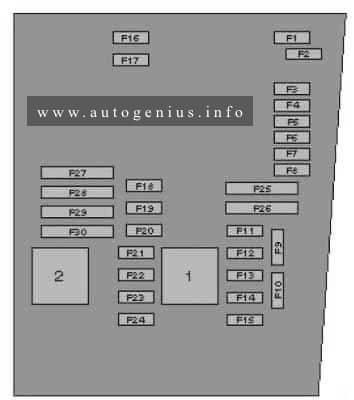
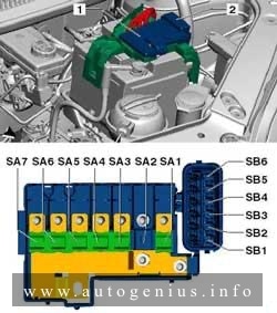
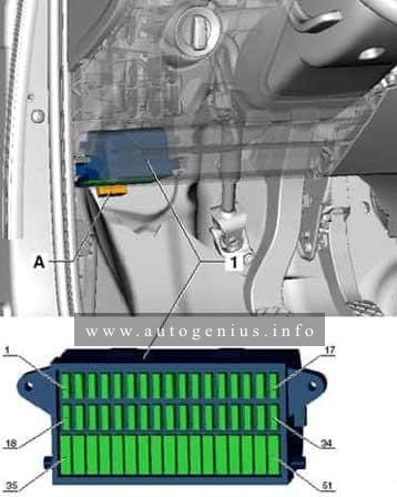
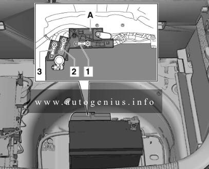
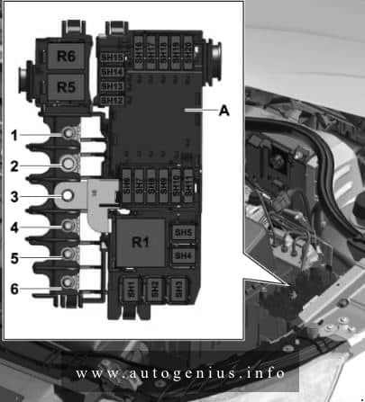
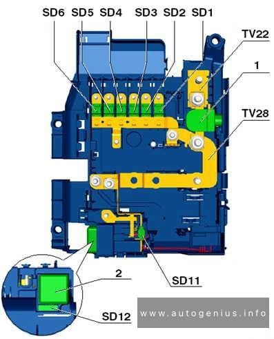
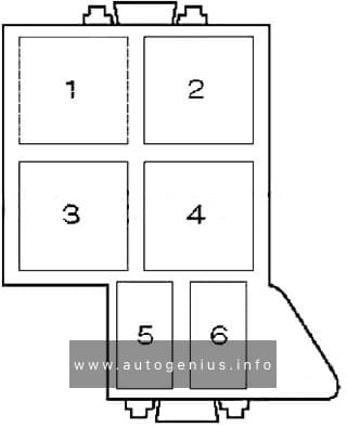
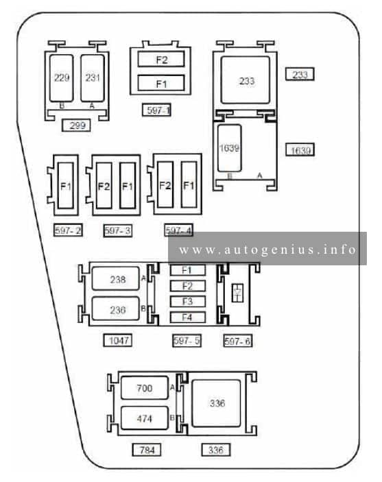
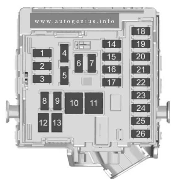
Fuse box above the battery
Fuse box diagram

Engine Pre-Fuse Box
| No. |
A |
Description |
| 1 | 100 | Fuse Block – Instrument Panel |
| 2 | 100 | Fuse Block – Instrument Panel |
| 3 | 80 | Electrical Power Steering (EPS) (NJ1) |
| 4 | N/A | Not Used |
| 5 | 250 | Fuse Block – Battery Auxiliary |
| 6 | 250/500 | Starter Motor |
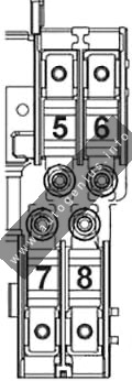
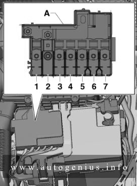
Engine Pre-Fuse Box
| No. |
A |
Description |
| 5 | 80 | Glow Plug Control Module |
| 6 | 100 | Electrical Auxiliary Heater |
| 7 | N/A | Not Used |
| 8 | N/A | Not Used |
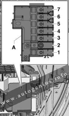
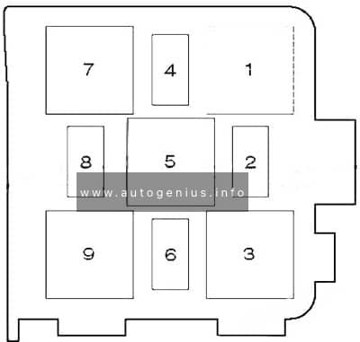
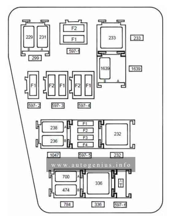
Relay Box
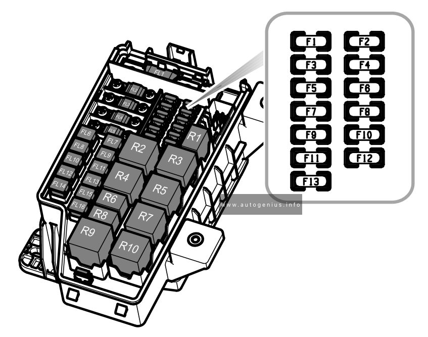
Fuse box diagram
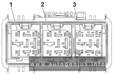
Relays
| No. |
Relays |
| 1 | Cooling Fan Left Medium Speed Relay |
| 2 | Cooling Fan Speed Control 2 Relay |
| 3 | Cooling Fan Right Medium Speed Relay |
WARNING: Terminal and harness assignments for individual connectors will vary depending on vehicle equipment level, model, and market.