Acura EL (1.6 EL) (1997 – 2000) – fuse and relay box diagram
Years of production: 1997, 1998, 1999, 2000
This article focuses on the first-generation Acura EL (1.6EL), manufactured between 1997 and 2000. It includes fuse box diagrams for the 1997, 1998, 1999, and 2000 models, provides details on the location of the fuse panels within the vehicle, and explains the function of each fuse (fuse layout).
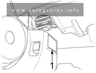
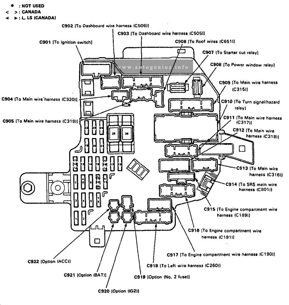
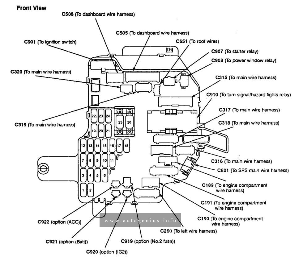
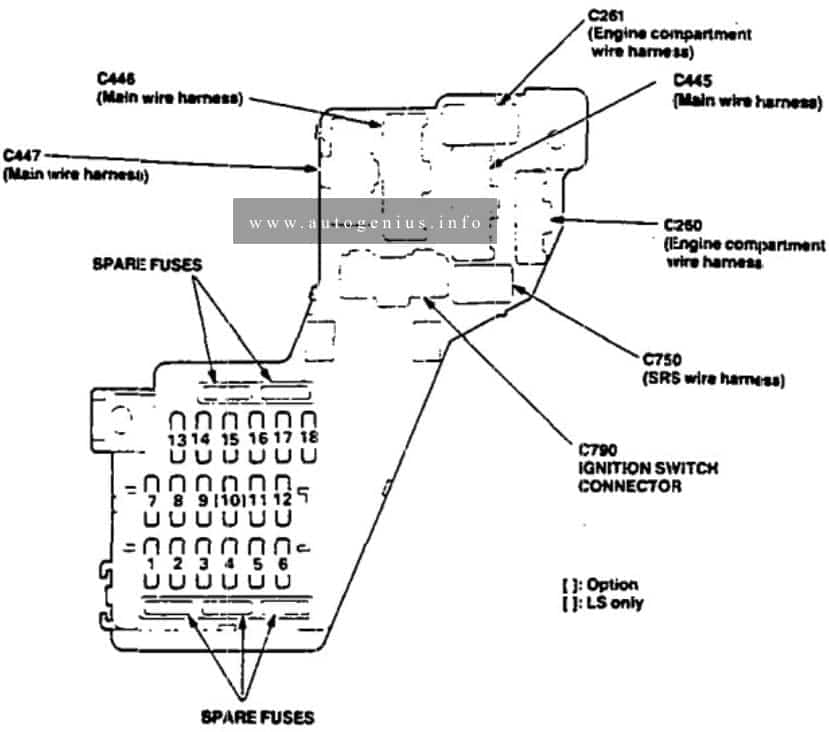
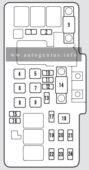
Passenger Compartment Fuse Box
Fuse Box Location
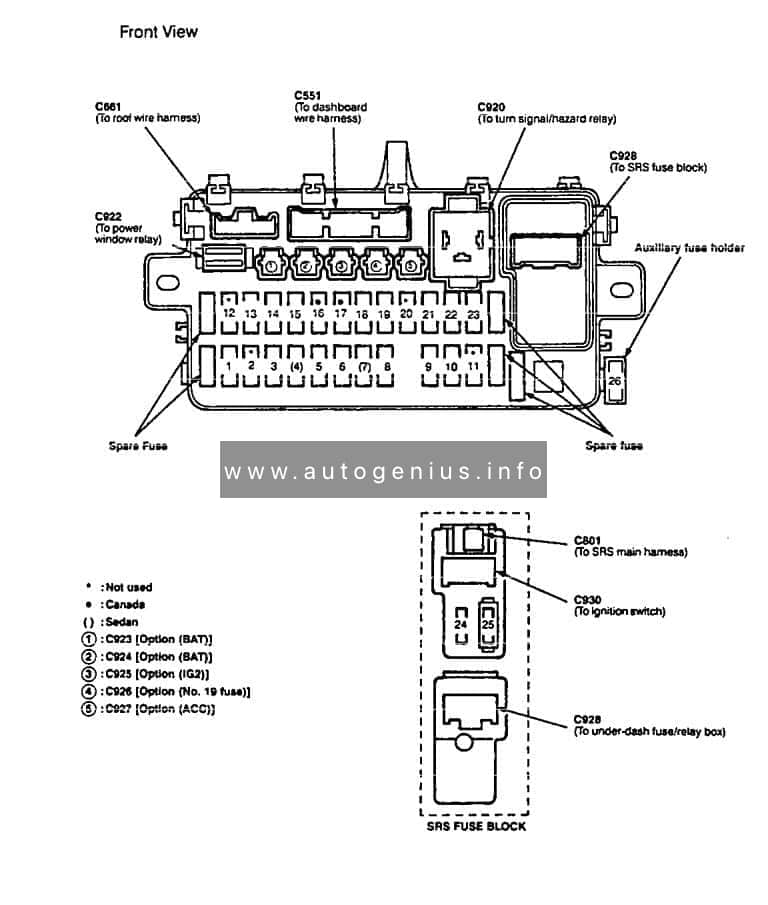
The interior fuse box is located below the dashboard.
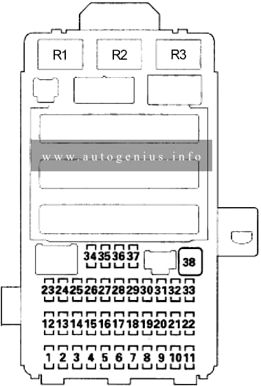
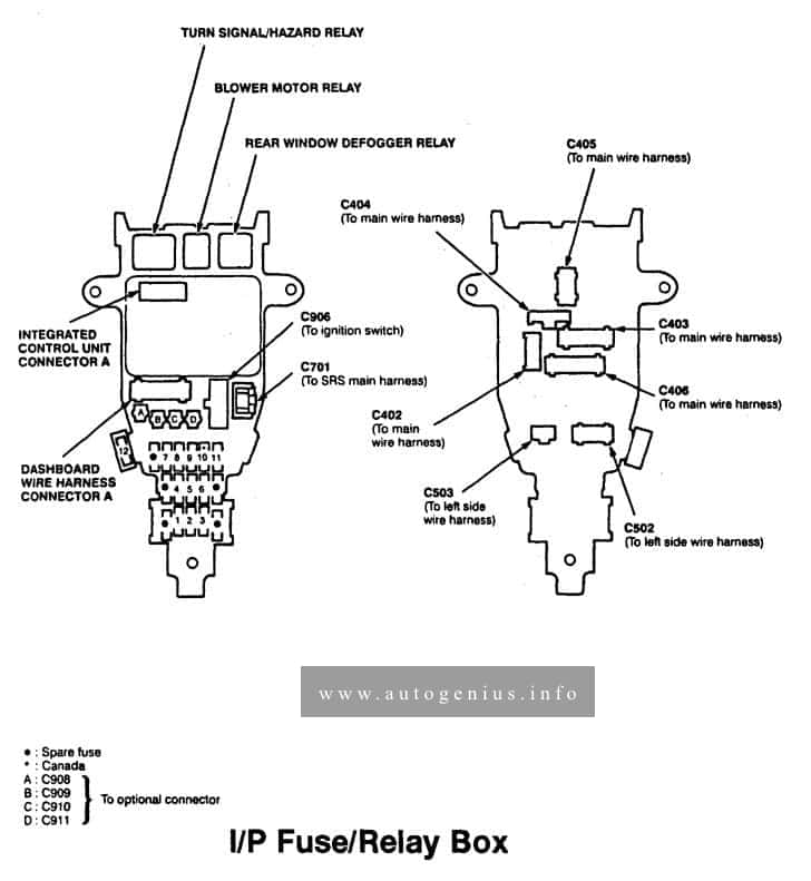
Fuse Box Diagram
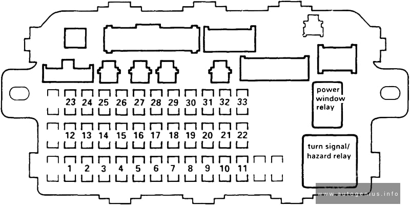
Assignment of the fuses in the instrument panel
| № | Amps | Circuit(s) Protected |
|---|---|---|
| 1 | – | Not used |
| 2 | – | Not used |
| 3 | – | Not used |
| 4 | 10A | Resistor Right headlight (high beam) |
| 5 | 10A | High beam indicator Left headlight (high beam) Resistor |
| 6 | – | Not used |
| 7 | 20A | Left rear power window motor |
| 8 | 20A | Right rear power window motor |
| 9 | – | Not used |
| 10 | 20A | Front passenger’s window motor |
| 11 | 20A | Driver’s window motor Power window master switch |
| 12 | 7.5A | Turn signal/hazard relay |
| 13 | 15A | PGM-Fl main relay SRS unit (VA) |
| 14 | 7.5A | Cruise control unit Keyless/security control unit |
| 15 | 7.5A | Alternator Charging system light (Wire color: BLK/WHT) EVAP purge control solenoid valve Heated oxygen sensor Secondary heated oxygen sensor Vehicle speed sensor |
| 16 | 7.5A | ABS control unit Rear window defogger relay |
| 17 | 7.5A | A/C compressor clutch relay A/C thermostat Condenser fan relay Heater control panel Mode control motor Power mirror actuator Power mirror defogger Radiator fan relay Recirculation control motor Option connector |
| 18 | 7.5A | Daytime runninq liqhts control unit |
| 19 | 7.5A | Back-up lights |
| 20 | 10A | Daytime running lights control unit Keyless/security control unit |
| 21 | 10A | Right headlight (low beam) |
| 22 | 10A | Left headlight (low beam) |
| 23 | 10A | SRS unit (VB) |
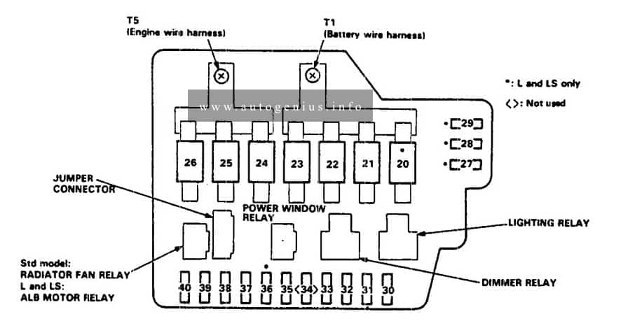
| 24 | 7.5A | Moonroof open relay Moonroof close relay Power window relay |
| 25 | 7.5A | ABS indicator circuit A/T gear position dimming circuit Clock Cruise indicator circuit Gauge assembly Interlock control unit Shift lock solenoid SRS indicator circuit Integrated control unit |
| 26 | 20A | Windshield wiper motor Windshield washer motor |
| 27 | 15A | Accessory power socket |
| 28 | 15A | Audio unit Stereo amplifier (AFB sound system) Option connector |
| 29 | – | Not used |
| 30 | 7.5A | Audio unit light A/T gear position console light A/T gear position indicator dimming circuit Clock Cruise indicator circuit Cruise main switch light Dash lights brightness controller Gauge lights Hazard warning switch light Heater control panel lights Integrated control unit Option connector |
| 31 | 7.5A | ECM (M/T) PCM (A/T) PGM-FI main relay Keyless/security control unit Starter cut relay Integrated control unit |
| 32 | 7.5A | Front parking lights License plate lights Taillights |
| 33 | 7.5A | Key interlock solenoid |
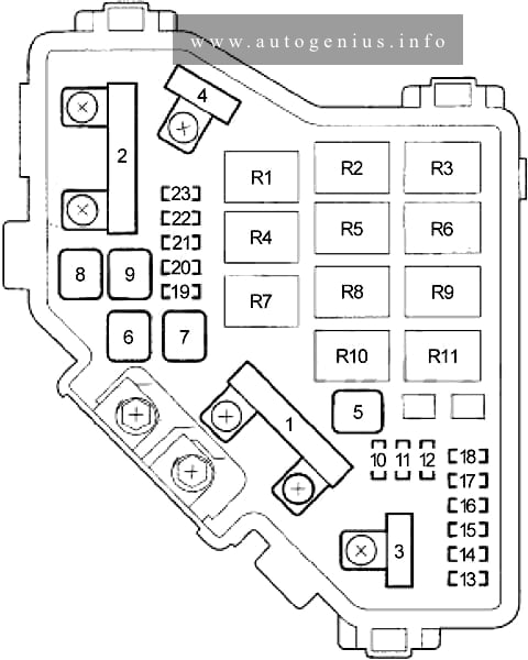
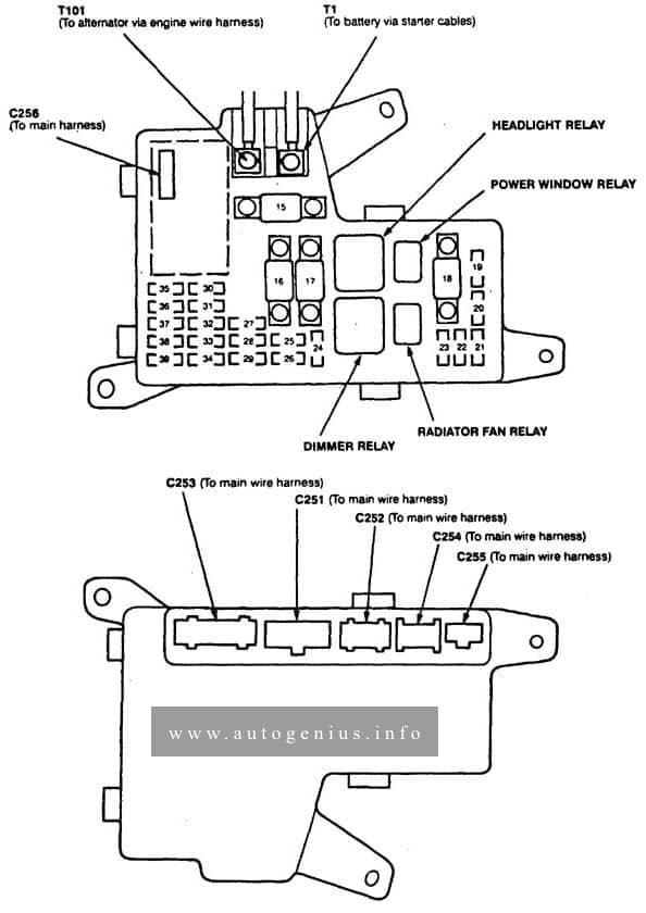
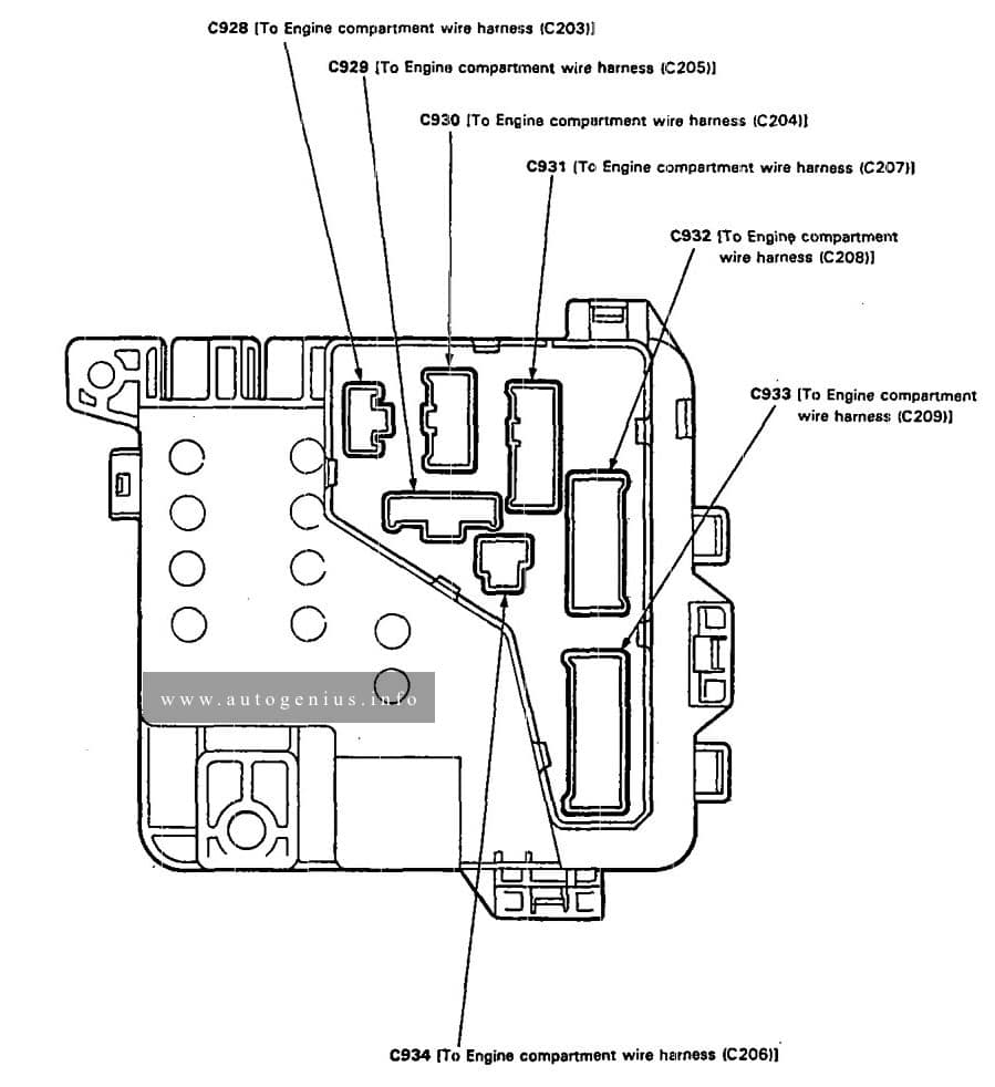
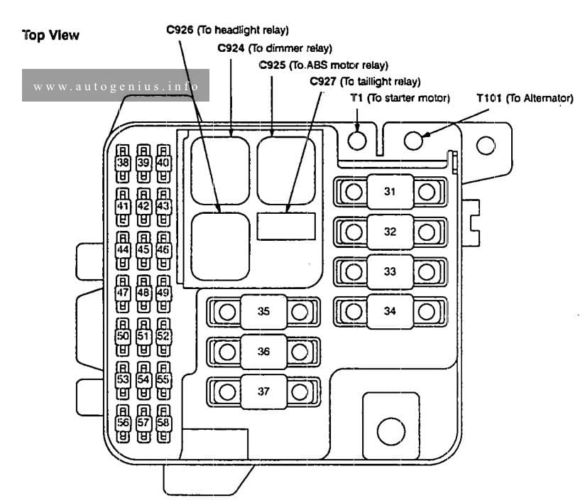
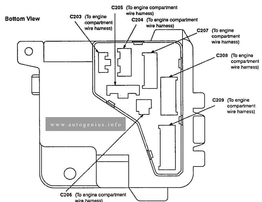
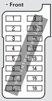
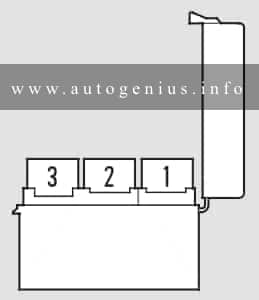
Engine Compartment Fuse Box
Fuse Box Location
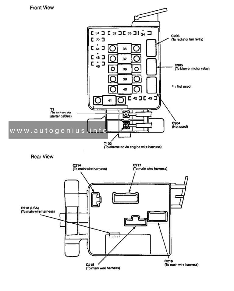
The under-hood fuse box is on the passenger’s side, next to the battery.
Fuse Box Diagram
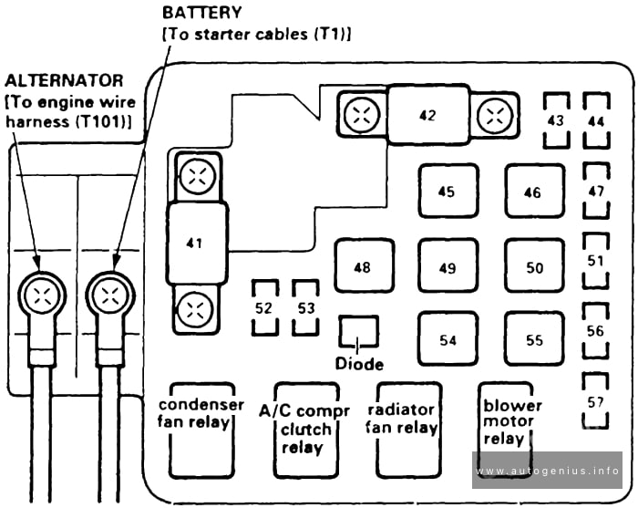
Assignment of the fuses in the engine compartment
| № | Amps | Circuit(s) Protected |
|---|---|---|
| 41 | 80A | All |
| 42 | 40A | Ignition switch (BAT) |
| 43 | 7.5A | Ceiling light Data link connector Trunk light Integrated control unit (under-dash fuse relay/box socket) |
| 44 | 15A | PGM-FI main relay |
| 45 | – | Not used |
| 46 | 40A | Power window relay |
| 47 | 7.5A | Audio unit Clock ECM (M/T) Heater control panel PCM (A/T) Security indicator |
| 48 | 30A | № 20, 33 fuses (in under-dash tuse/relay box) № 21, 22 fuses (via security headlight relay or dimmer low switch) Combination light switch |
| 49 | – | Not used |
| 50 | 30A | Rear window defogger |
| 51 | 20A | Keyless/security control unit Moonroof motor |
| 54 | 40A | Option connector |
| 55 | 40A | Blower motor |
| 56 | 20A | Condenser fan motor A/C compressor clutch |
| 57 | 20A | Radiator fan motor |
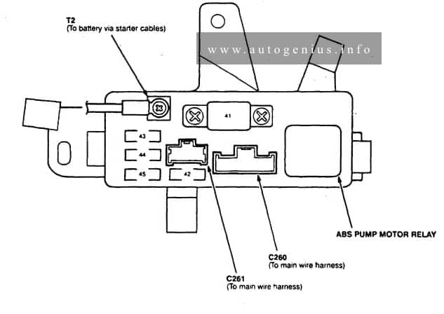
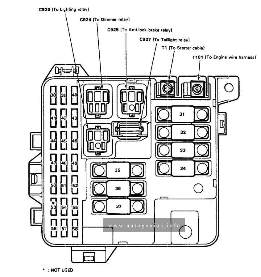
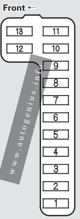
ABS Fuse Box
Fuse Box Diagram
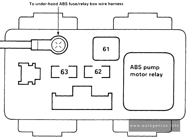
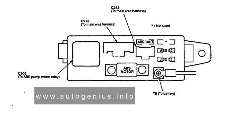
ABS Fuse Box
| № | Amps | Circuit(s) Protected |
|---|---|---|
| 61 | 40A | ABS pump motor |
| 62 | 7.5A | ABS control unit (MCK) |
| 63 | 20A | ABS control unit (BAT) |
WARNING: Terminal and harness assignments for individual connectors will vary depending on vehicle equipment level, model, and market.