Volkswagen Amarok II (2022 – 2024) – fuses and relay box diagram

Volkswagen Amarok II (2022 – 2024) – fuses and relay box diagram


Year of production: 2022, 2023, 2024


This article covers the second-generation Volkswagen Amarok, which has been available since 2022. Inside, you will find fuse box diagrams for the 2022, 2023 and 2024 Volkswagen Amarok, along with details on the locations of the fuse panels within the vehicle and the functions of each fuse (fuse layout).


Passenger compartment

Fuse Box Location

Volkswagen Amarok (II; 2022 - 2024) - fuse and relay location - passenger compartment
Volkswagen Amarok (II; 2022 – 2024) – fuse and relay location – passenger compartment


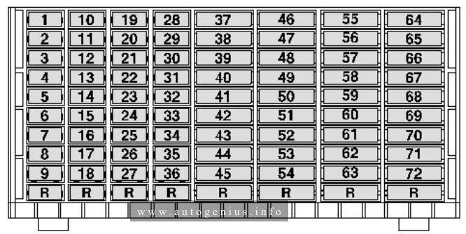
Fuse Box Diagram (-SC-/-SX2-)

Volkswagen Amarok (II; 2022 - 2024) - fuse and relay location - passenger compartment (-SC-, -SX2-)
Volkswagen Amarok (II; 2022 – 2024) – fuse and relay location – passenger compartment (-SC-, -SX2-)


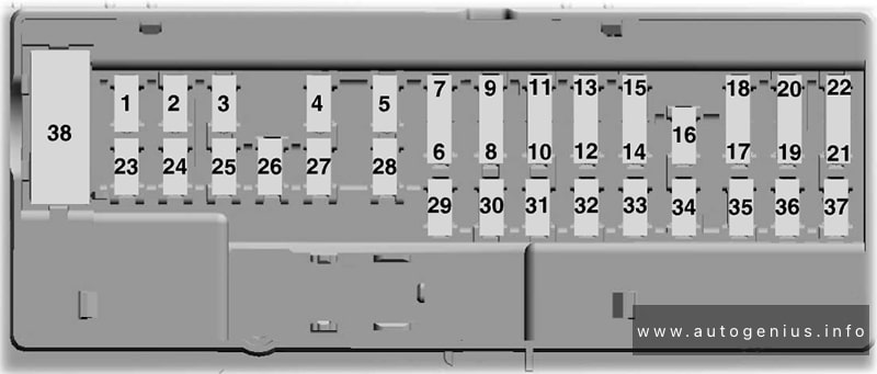
Assignment of the fuses and relays in the instrument panel

Amps Function / component
SC2 10A Driver side interior locking button for central locking system
Front passenger side interior locking button for central locking system
DC/AC converter with socket, 12V – 230V
Operating unit for window regulator in driver door
SC3 7.5A Charging unit 1 for mobile devices (Wireless)
SC4
SC5
SC6 10A Anti-theft alarm system horn
Battery backup sounder
SC7
SC8 5A Emergency call module control unit and communication unit
SC9 5A Interior monitor send and receive module 1
SC10
SC11
SC12 7.5A Data bus diagnostic interface
Selector lever
Heater and air conditioning system control unit
SC13 7.5A Steering column electronics control unit
Dash panel insert
SC14
SC15 15A Multimedia system control unit
Diagnostic connection
SC16
SC17 7.5A Control unit for cornering light and headlight range control
Control unit for reducing agent metering system
Trailer brake switch
SC18 7.5A Relay and fuse carrier A for special vehicles
Auxiliary switch
Tachograph
SC19 5A Operating unit for lighting (Headlamp switch pack)
SC20 5A Ignition/starter switch
Starter button
SC21
SC22
SC23
SC24
SC25
SC26
SC27
SC28
SC29 15A Display unit for front information display and operating unit control unit
Tachograph
SC30 5A Brake switch
SC31 10A Centre operating unit for dash panel
Switch module 1 in centre console
Entry and start authorisation control unit
SC32 20A Radio
SC33
SC34 30A Run/start relay
Fuse 17 on fuse holder C
Fuse 18 on fuse holder C
Fuse 36 on fuse holder C
Fuse 37 on fuse holder C
SC35
SC36 15A Parking aid control unit
Rear seat module
SC37 20A Steering column electronics control unit
Heatedsteering wheel
Automatic anti-dazzle interior mirror
SC38 30A Power window switch


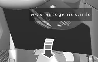
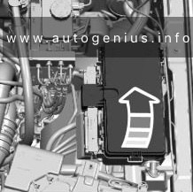
Engine Compartment Fuse Box

Fuse Box Location

Volkswagen Amarok (II; 2022 - 2024) - fuse and relay location - engine  compartment
Volkswagen Amarok (II; 2022 – 2024) – fuse and relay location – engine compartment


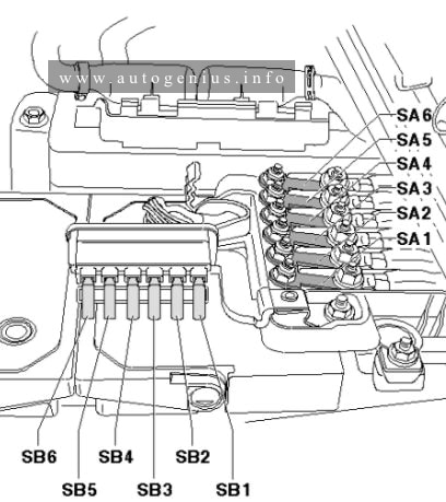
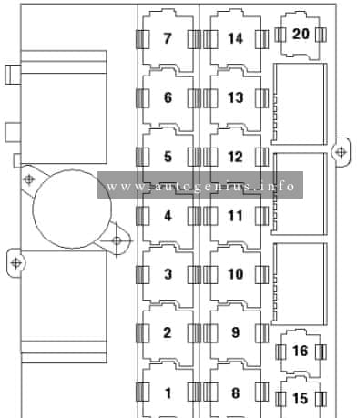
Fuse Box Diagram (-SX1-)

Volkswagen Amarok (II; 2022 - 2024) - fuse and relay location - engine  compartment (-SB-/-SX1-)
Volkswagen Amarok (II; 2022 – 2024) – fuse and relay location – engine compartment (-SB-/-SX1-)


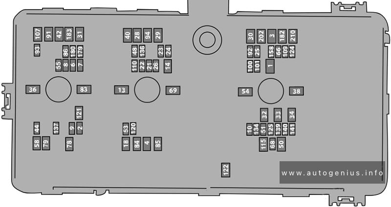
Assignment of the fuses in the engine compartment (-SB-/-SX1-)

Amps Function / component
SB1 30A Onboard supply control unit (BCM 1)
SB2 20A Heater element for crankcase breather (Diesel 2.0L)
SB3 30A Onboard supply control unit (BCM 2)
SB4 30A Fuel pump control unit
Fuse 120 on fuse holder B
SB6 25A Engine/motor control unit
SB7 30A Charge pressure control solenoid valve 2 (Diesel 2.0L, 3.0L)
Turbine changeover valve (Diesel 2.0L, 3.0L)
Exhaust gas recirculation cooling bypass valve (Diesel 2.0L, 3.0L)
Camshaft control valve 1 (Petrol)
Exhaust camshaft control valve 1 (Petrol)
Lambda probe 1 before catalytic converter (Petrol)
Lambda probe 1 after catalytic converter (Petrol)
Activated charcoal filter solenoid valve 1 (Petrol)
SB8 20A Radiator blind control motor 2
Radiator fan relay
Radiator fan 2 relay
Valve for oil pressure control
Heater element for crankcase-breather (Diesel 3.0L)
Air conditioner compressor
Turbocharger air recirculation valve (Petrol)
SB9 20A Control unit for NOx sender (Diesel 2.0L, 3.0L)
Control unit 2 for NOx sender (Diesel 2.0L, 3.0L)
Control unit 3 for NOx sender (Diesel 2.0L, 3.0L)
Control unit 1 for particulate sensor (Diesel 2.0L)
Glow plug relay (Diesel 2.0L, 3.0L)
Automatic glow period control unit (Diesel 2.0L, 3.0L)
Onboard supply control unit 2
60-pin electrical connector Pin 23
Ignition coil 1~4 with output stage (Petrol)
4×4 relay coil
Turbocharger surge valve (Petrol)
Oil pump solenoid (Petrol)
Engine coolant bypass valve (Petrol)
SB10 20A Fuel pressure regulating valve (Diesel 3.0L)
Fuel metering valve (Diesel 3.0L)
Automatic gearbox control unit
SB13 40A Fresh air blower control unit
SB18 30A Starter
SB21 10A Automatic headlamp levelling
Front left headlight
Front right headlight
SB23 10A ABS control unit
SB24 10A Automatic glow period control unit (Diesel 2.0L, 3.0L)
Power steering control unit
Engine/motor control unit
SB25 20A All-wheel drive control unit
Reversing camera
Driveline control module
SB26 15A Automatic gearbox control unit
Auxiliary hydraulic pump 1 for gearbox oil
SB28 60A ABS control unit
SB29 60A ABS control unit
SB30 40A Operating unit for front left seat adjustment (LHD)
Operating unit for front right seat adjustment (RHD)
SB31 40A Operating unit for front right seat adjustment (LHD)
Operating unit for front left seat adjustment (RHD)
SB32 20A 12V socket (first row)
SB33 20A 12V socket 2 (rear console)
SB34 20A Rear cargo power outlet – bedliner power point
SB36 60A DC/AC converter without socket, 12V – 230V
SB38 30A Heater and air conditioning system control unit
SB42 30A Trailer detector control unit
SB44 10A Brake light switch
SB48 30A Rear heated seat module – right
SB50 40A Heated rear window
SB53 15A Differential lock valve 1
SB54 40A Driveline control module
SB55 30A Trailer tow park lamp
SB58 15A Trailer tow backup lamp
SB64 40A All-wheel drive control unit
SB68 20A Control unit for electronic steering column lock
SB69 30A Windscreen wiper
SB78 50A Heated windscreen: Right heating circuit
SB79 50A Heated windscreen: Left heating circuit
SB83 50A Auxiliary heater (Diesel 3.0L)
SB84 50A Auxiliary heater (Diesel 3.0L)
SB85 50A Auxiliary heater (Diesel 3.0L)
SB86 15A Control unit for reducing agent metering system
Automatic glow period control unit
Selective catalytic reduction system heater 2 (Diesel 2.0L, 3.0L)
SB91 40A Trailer detector control unit
SB92 10A Accessory
SB93 5A Remote control receiver for auxiliary heater
SB94 20A Auxiliary heater control unit
SB100 20A Front left headlight
SB101 20A Front right headlight
SB107 30A Trailer detector control unit
SB109 20A Digital sound package control unit
Amplifier
SB110 30A Trailer socket
SB112 5A Remote control receiver for auxiliary heater
SB113 20A Auxiliary heater control unit
SB115 30A Control unit fa|r HD ad area roller blind
SB120 10A Onboard supply control unit 2
60-pin connector Pin 20
Fuse 121 on fuse holder B
Fuel filter heater relay
Water in fuel heater relay coils (Diesel)
SB121 40A Fuel filter heater module (Diesel 2.0L, 3.0L)
SB122 30A Onboard supply control unit 2
Transfer box control motor
SB124 5A Rain sensor
SB136 30A Rear heated seat module – left
SB137 20A Driver assist systems control unit
SB140 5A USB connection 2 (rear console)
SB141 5A USB charging socket in headlining
SB179 15A Control unit for reducing agent metering system (Diesel)
SB180 10A Control unit for reducing agent metering system (Diesel)
SB182 60A Front passenger door control unit (LHD)
Driver door control unit (RHD)
SB183 60A Driver door control unit (LHD)
Front passenger door control unit (RHD)
SB202 60A Onboard supply control unit (Body control module B+)
SB210 30A Onboard supply control unit (Body control module start-stop)


Fuse Panel A (-SA-)
Volkswagen Amarok (II; 2022 - 2024) - fuse and relay diagram - engine  compartment (-SA-)
Volkswagen Amarok (II; 2022 – 2024) – fuse and relay diagram – engine compartment (-SA-)


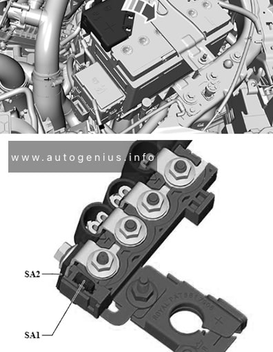
Assignment of the fuses in the engine compartment (holder A)

Amps Function / component
SA1 3A Battery monitor control unit
SA2 125A Connection and distribution box 3 (-SX3-)


Fuse Panel D (-SD-)
Volkswagen Amarok (II; 2022 - 2024) - fuse and relay diagram - engine  compartment (-SD-)
Volkswagen Amarok (II; 2022 – 2024) – fuse and relay diagram – engine compartment (-SD-)


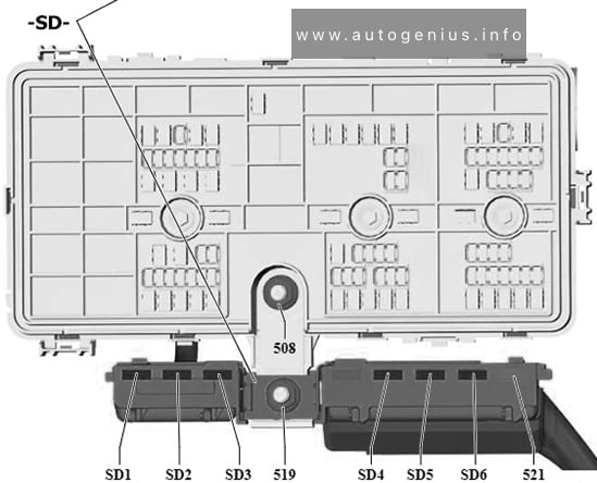
Assignment of the fuses in the engine compartment (-SD-)

Amps Function / component
SD1 80A Radiator fan relay
SD2 80A Petrol: Radiator fan 2 relay
SD3 70A Diesel (2.0L, 3.0L):
Automatic glow period control unit
Glow plug relay
SD4 210A (Petrol)
250A (Diesel)
Petrol: Alternator with voltage regulator
Diesel (2.0L, 3.0L): Alternator with voltage regulator
SD5 50A Power steering control unit
SD6 50A Power steering control unit


Fuse Panel Holder 3 (-SX3-)
Volkswagen Amarok (II; 2022 - 2024) - fuse and relay diagram - engine  compartment (-SX3-)
Volkswagen Amarok (II; 2022 – 2024) – fuse and relay diagram – engine compartment (-SX3-)


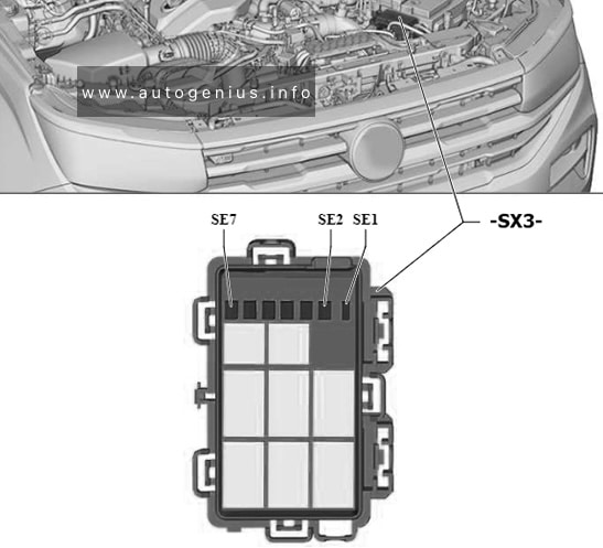
Assignment of the fuses in the engine compartment (holder 3)

Amps Function / component
SE1 5A Relay 1 for external use
SE2 not assigned
SE3 15A Relay 2 for external use
SE4 15A Relay 3 for external use
SE5 15A Relay 4 for external use
SE6 25A Relay 5 for external use
SE7 25A Relay 6 for external use


WARNING: Terminal and harness assignments for individual connectors will vary depending on vehicle equipment level, model, and market.

Volkswagen Amarok (2010 – 2017) – fuse and relay box diagram

Volkswagen Amarok (2010 – 2017) – fuse and relay box diagram

Year of production: 2010, 2011, 2012, 2013, 2014, 2015, 2016, 2017


The Volkswagen Amarok, a mid-size pickup truck, was produced from 2010 to 2020. In this article, you’ll find fuse box diagrams for the 2010 through 2017 models, along with information on the location of the fuse panels inside the vehicle and details about the function and layout of each fuse and relay.

Passenger compartment

Fuse box diagram (holder C)

Volkswagen Amarok (2010 - 2017) - fuse and relay box diagram - passenger compartment (holder C)
Volkswagen Amarok (2010 – 2017) – fuse and relay box diagram – passenger compartment (holder C)


Assignment of the fuses in the passenger compartment (fuse holder C)

Fuse Current Flow Diagram designation Ampere rating [A] Function/component
1 Fuse 1 on fuse holder C -SC1- 10 ABS cintrol unik -J104-, TCS and ESP button -E256-, Driving program button -E598-
2 Fuse 2 on fuse holder C -SC2- 10 Steering column electronics control unit -J527-
3 Fuse 3 on fuse holder C -SC3- 10 Reversing switch -F41-
4 Fuse 4 on fuse holder C -SC4- 15 Onboard supply control unit -J519-
5 Fuse 5 on fuse holder C – SC5- 5 Air mass meter -G70-
6 Fuse 6 on fuse holder C -SC6- 5 Trailer detector control unit -J345-
7 Fuse 7 on fuse holder C -SC7- 5 Interface for external use
8 Fuse 8 on fuse holder C -SC8- 10 Electronic ignition lock -D9-
9 Fuse 9 on fuse holder C -SC9- 10 Airbagcontrol unit -J234-, Front passenger side airbag deactivated warning lamp -K145-
10 Fuse 10 on fuse holder C -SC10- 5 Engine control unit -J623-
11 Fuse 11 on fuse holder C -SC11- 15 Differentral lock control unit -J187-
12 Fuse 12 on fuse holder C – SC12- 10 Fuel pump 1 -V276-
13 Fuse 13 on fuse holder C -SC13 5 Exhaust flap valve -N220-, Exhaust gas recirculation cooler change-over calve -N345-
14 Fuse 14 on fuse holder C -SC14 15 Continued coolant circulation pump -V51-
15 Fuse 15 on fuse holder C -SC15- 5 Engine control unit -J623-
16 Fuse 16 on fuse holder C -SC16- 10 Rear fog light warning lamp -K13-, Rear left fog light bulb -L46-, Rear right fog light bulb -L47-
17 Fuse 17 on fuse holder C – SC17- 5 Right tail light bulb -M2-, Right side light bulb -M3-
18 Fuse 18 on fuse holder C -SC18- 5 Left side light bulb -M1-, left tail light bulb -M4-
19 Fuse 19 on fuse holder C -SC19 15 Onboard supply control unit -J519-
20 Fuse 20 on fuse holder C -SC20- 15 Onboard supply control unit -J519-
21 Fuse 21 on fuse holder C -SC21- 5 Onboard supply control unit -J519-
22 Fuse 22 on fuse holder C -SC22- Vacant
23 Fuse 23 on fuse holder C -SC23- 15 Engine control unit -J623-
24 Fuse 24 on fuse holder C -SC24 10 Alarm horn -H12-
25 Fuse 25 on fuse holder C -SC25- 10 Heater element fon crancase breather -N79-
26 Fuse 26 on fuse holder C -SC26 5 Right day driving light bulb -L175-
27 Fuse 27 on fuse holder C -SC27- 5 Left day driving light bulb -L174-
28 Fuse 28 on fuse holder C -SC28- 15 Number plate left light -X4, Number plate right light -X5-
29 Fuse 29 on fuse holder C -SC29- 10 Left headlight range control motor -V48-
30 Fuse 30 on fuse holder C -SC30- 10 Left main beam bulb -L125-
31 Fuse 31 on fuse holder C -Sc31- Vacant
32 Fuse 32 on fuse holder C -SC32- 10 Right main beam bulb -L126-
33 Fuse 33 on fuse holder C -SC33- 5 Mirror adjustment switch -E43-
34 Fuse 34 on fuse holder C -Sc34- 15 Vacant
35 Fuse 35 on fuse holder C -SC35- 15 Lambda probe 1 upstream of catalytic converter -GX10-
36 Fuse 36 on fuse holder C -Sc36- 5 Engine control unit -J623-
37 Fuse 37 on fuse holder C -SC37- Vacant
38 Fuse 38 on fuse holder C -SC38- 15 12V socket -U5-
39 Fuse 39 on fuse holder C -SC39- 25 Trailer detector control unit -J345-
40 Fuse 40 on fuse holder C -SC40- 25 Trailer detector control unit -J345-
41 Fuse 41 on fuse holder C -SC41- 25 Trailer detector control unit -J345-
42 Fuse 42 on fuse holder C -SC42- 15 Diagnostic connection -U31-, steering column electronics control unit -J527-, Air conditioning system pressure switch -F129-, Air quality sensor -G238-, differential lock control unit -J187-, transfer box control unit -J646-, dash panel insert -K-, High level brake light bulb -M25-, Brake light switch -F-, Display unit -K40-
43 Fuse 41 on fuse holder C – Sc43- 25 Onboard supply control unit -J519-
44 Fuse 44 on fuse holder C -SC44- 30 Onboard supply control unit -J519-
45 Fuse 45 on fuse holder C -SC45- 15 Diagnostic connection -U31-, Dash panel insert -K-, Steering column electronics control unit -J527-, Air conditioning system control unit -J301-, Climatronic control unit -J255-, Heater/heat output switch -E16-
46 Fuse 46 on fuse holder C -SC46- 25 Transfer boc control unit -J646-
47 Fuse 47 on fuse holder C -SC47- 20 Onboard supply control unit
48 Fuse 48 on fuse holder C -SC48- 20 Driver door control unit -J386-
49 Fuse 49 on fuse holder C -SC49- 20 Front passanger door control unit -J387-
50 Fuse 50 on fuse holder C -SC50- 20 Rear left door control unit -J388-
51 Fuse 51 on fuse holder C -SC51- 20 Rear right door control unit -J389-
52 -Fuse 52 on fuse holder C -SC52- 15 Electric socket -U-
53 Fuse 53 on fuse holder C -SC53- 20 Left fog light bulb -L22-
54 Fuse 54 on fuse holder C -SC54- 15 Cigarette lighter -U1-
55 Fuse 55 on fuse holder C -SC55- 15 Right headlight range control motor -V49-
56 Fuse 56 on fuse holder C -SC56- Vacant
57 Fuse 57 on fuse holder C -SC57- 30 Seat heating button, left -E653-, Seat heating button, right – E654-, Seat heating control unit -J882-
58 Fuse 58 on fuse holder C -SC58- Vacant
59 Fuse 59 on fuse holder C -SC59- 20 12V socket -UX3-
60 Fuse 60 on fuse holder C -SC60- 5 Trailer detector unit -J345-, Diagnostic connection -U31-, Onboard supply control unit -J519-
61 Fuse 61 on fuse holder C -SC61- 5 Trailer detector control unit -J345-, Diagnostic connection -U31-, Onboard supply control unit -J519-
62 Fuse 62 on fuse holder C -SC62- 20 Auxiliary heater control unit -J364-, Circulation pump -V55-
63 Fuse 63 on fuse holder C -SC63- 10 Load area illumination bulb -M53-
64 Fuse 64 on fuse holder C -SC64- 30 Heater/heat output switch -E16-, Climatronic control unit -J255-, Air conditioning system control unit -J301-
65 Fuse 65 on fuse holder C -SC65- 15 Engine control unit -J623-
66 Fuse 66 on fuse holder C -SC66- 30 Onboard supply control unit -J519-
67 Fuse 67 on fuse holder C -SC67- 30 Radio -R-, Control unit with display for radio and navigation system -J503-
68 Fuse 68 on fuse holder C -SC68- Vacant
69 Fuse 69 on fuse holder C -SC69- 15 Interface for external use
70 Fuse 70 on fuse holder C -SC70- 5 Interface for external use
71 Fuse 71 on fuse holder C -SC71- 25 Interface for external use
72 Fuse 72 on fuse holder C -SC72- 10 Interface for external use

Engine compartment

Fuse box diagram (holder A -SA-)

Volkswagen Amarok (2010 - 2017) - fuse and relay box diagram - engine compartment (holder A and holder B)
Volkswagen Amarok (2010 – 2017) – fuse and relay box diagram – engine compartment (holder A and holder B)


Assignment of the fuses in the engine compartment (fuse holders A)

Fuse Current flow diagram designation Ampere rating [A] Function/component
1 Fuse 1 on fuse holder A -SA1- 175 Alternato -C-
2 Fuse 2 on fuse holder A -SA2- 175 Fuse 4 on fuse holder C -SC4-, Fuse 8 on fuse holder C -SC8-, Fuse 11 on fuse holder C -SC11-, Fuse 15 on fuse holder C -SC15-, Fuse holder C -SC19 – SC24-, Fuse holder C -SC43 – SC51-, Fuse holder SC62 – SC64-, Fuse holder C -SC66 – SC67-
3 Fuse 3 on fuse holder A -SA3- 40 Interface for external use
4 Fuse 4 on fuse holder A -SA4- 80/110 Radiator fan -V7-
5 Fuse 5 on fuse holder A -SA5- 50 Automatic glow period control unit J179-
6 Fuse 6 on fuse holder A -SA6- 80 Fuse holder C -SC39 – SC41-


Engine compartment

Fuse box diagram (holder B -SB-)

Volkswagen Amarok (2010 - 2017) - fuse and relay box diagram - engine compartment (holder A and holder B)
Volkswagen Amarok (2010 – 2017) – fuse and relay box diagram – engine compartment (holder A and holder B)


Assignment of the fuses in the engine compartment (fuse holders B)

Fuse Current Flow Diagram designation Ampere rating [A] Function/component
1 Fuse 1 on fuse holder B -SB1- 30 ABS control unit J104-
2 Fuse 2 on fuse holder B -SB2- 30 Fuel pump relay -J17-, Fuel system pressurisation pump -G6-
3 Fuse 3 on fuse holder B -SB3- 10 ABS control unit -J104-
4 Fuse 4 on fuse holder B -SB4- 5 Onboard supply control unit -J519-
5 Fuse 5 on fuse holder B -SB5- Vacant
6 Fuse 6 on fuse holder B -SB6- Vacant

Relays

Relay box diagram

Volkswagen Amarok (2010 - 2017) - fuse and relay box diagram - relay box
Volkswagen Amarok (2010 – 2017) – fuse and relay box diagram – relay box


Assignment of the relays in the relay box

Relay Description
1 Auxiliary coolant heater relay -J493-
2 Vacant
3 Vacant
4 Vacant
5 Vacant
6 Voltage supply relay 2 -J710- (53)
7 Terminal 15 voltage supply relay -J329- (100)
8 Coolant pump relay -J235-
9 Vacant
10 Vacant
11 Vacant
12 Voltage supply relay 1 -J701- (53)
13 Starter motor relay -J53- (53)
14 Fuel pump relay -J17- (404)
Terminal 30 voltage supply relay -J317- (404)
15 Current supply relay -J16- (100)
16 Terminal 58b relief relay -J374- (449)
20 Main relay -J271- (643)


WARNING: Terminal and harness assignments for individual connectors will vary depending on vehicle equipment level, model, and market.