RAM 4500 (2012) – fuse and relay box diagram
Year of production: 2012
The Ram 4500 (2012) is a heavy-duty chassis cab truck designed for commercial applications, sitting between the Ram 3500 and 5500 in the Ram lineup. The 2012 Ram 4500 offers a robust combination of power, durability, and upfit flexibility, making it ideal for businesses requiring a vehicle that can handle heavy loads, towing, and various custom configurations.
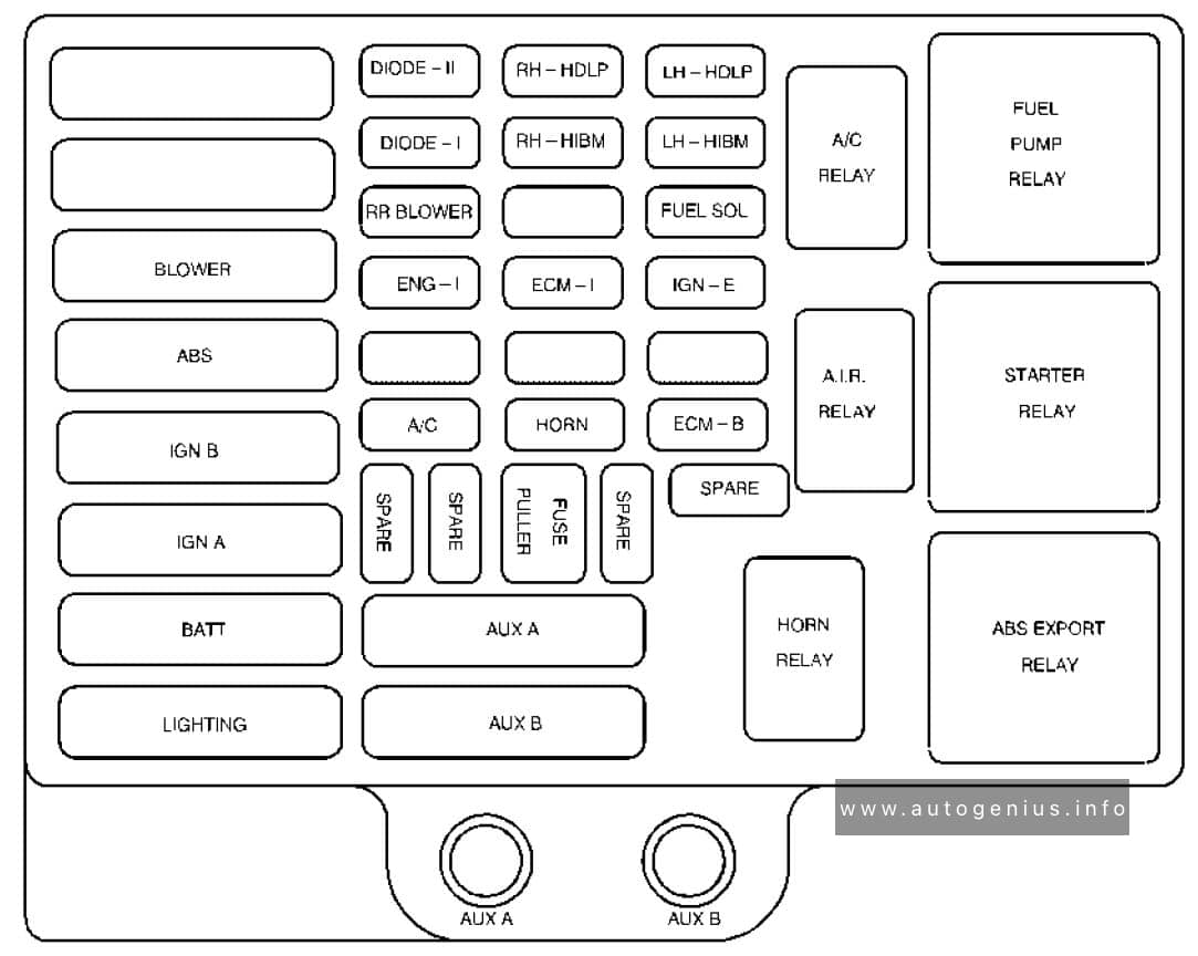
Totally Integrated Power Module
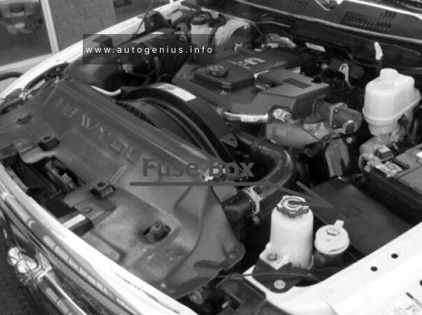
Fuse Box Location
The totally integrated power module (TIPM) is located in the engine compartment near the battery.
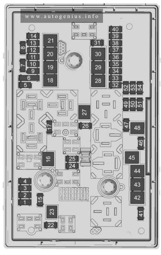
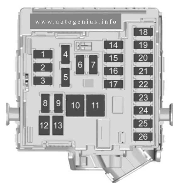
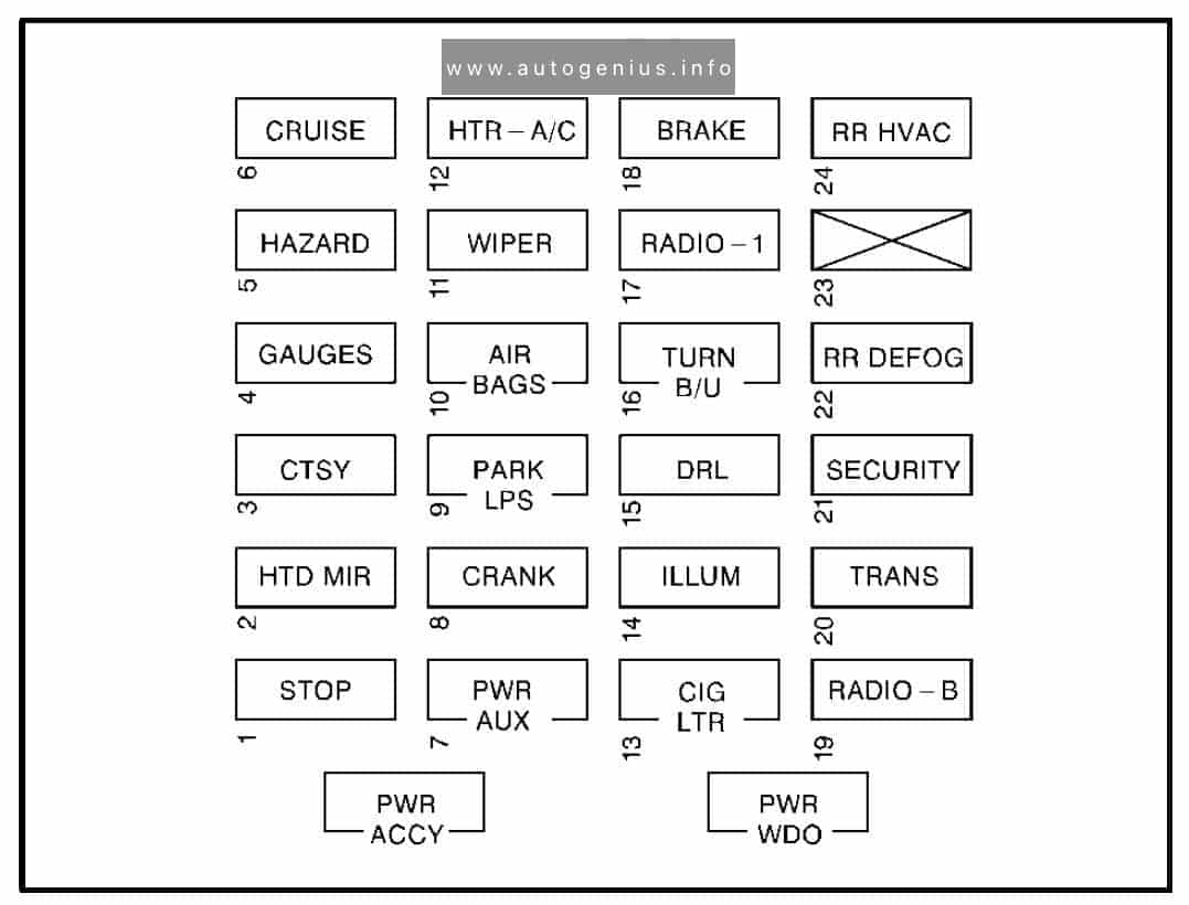
Fuse box diagram
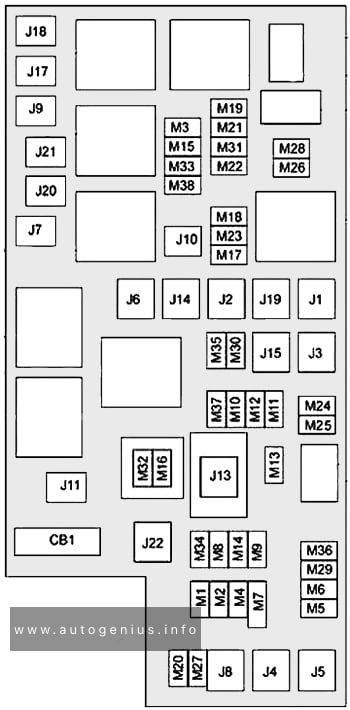
Assignment of the fuses in the engine compartment (2012)
| Cavity | Cartridge fuse | Mini Fuse | Description |
| J01 | 40 | Trailer Tow | |
| J02 | 30 | Electric Brake | |
| J03 | 30 | Diesel Powertrain Control Module – If Equipped | |
| J04 | 25 | Driver Door Node | |
| J05 | 25 | Passenger Door Node | |
| J06 | 40 | Antilock Brakes Pump/Stability Control System | |
| J07 | 30 | Antilock Brakes Valve/Stability Control System | |
| J08 | 40 | Power Seat | |
| J10 | 30 | Sway Bar Module – If Equipped | |
| J11 | 30 | Transfer Case Module | |
| J12 | 30 | Rear Defroster | |
| J13 | 60 | Main Ignition Off Draw (IOD) Fuse | |
| J14 | 20 | Trailer Tow Lamps/Park Lamps | |
| J15 | 40 | Front Blower | |
| J17 | 40 | Starter Motor Solenoid | |
| J18 | 20 | Powertrain Control Module Transmission Range | |
| J19 | 60 | Rad Fan Motor HI/Rad Fan Motor Low | |
| J20 | 30 | Front Wiper Ground/Low/High | |
| J21 | 20 | Washer Control | |
| J22 | 25 | Sunroof Module | |
| M1 | 15 | Stop Switch Lamp | |
| M5 | 25 | 115V AC Inverter | |
| M6 | 20 | Power Outlet (Instrument Panel or Front Console)/Rain Snsr | |
| M7 | 20 | Power Outlet (Rear Console or Center Seat) | |
| M8 | 20 | Front Heated Seat & Steering Wheel | |
| M9 | 20 | Rear Heated Seats | |
| M10 | 15 | Hands Free Module/Vanity Lamp/Universal GarageDoor Opener Module | |
| M11 | 10 | Climate Control System | |
| M12 | 30 | Radio/Amplifier | |
| M13 | 20 | Main #2 Instrument Cluster/Wireless Control Module/ITM/ Siren/Multifunction Switch (Steering Column Module) |
|
| M14 | 20 | Back Up Camera (Domestic Only) | |
| M15 | 20 | Power Seat Module(s)/Audio Telematics/Daytime Running Lights Relay/Instrument Cluster/Transfer Case Module | |
| M16 | 10 | Airbag Module | |
| M18 | 15 | Center Stop Lamp | |
| M19 | 25 | Automatic Shutdown 1 and 2 | |
| M20 | 15 | Instrument Cluster Interior Lighting /Sw Steering Wheel/Sw Bank | |
| M21 | 20 | Automatic Shutdown 3 | |
| M22 | 10 | Horns (Low/High) – Right | |
| M23 | 10 | Horns (Low/High) – Left | |
| M25 | 20 | Fuel Pump Motor/Diesel Lift Pump – If Equipped | |
| M26 | 10 | Driver’s Door Switch | |
| M27 | 10 | Ignition Switch | |
| M28 | 15 | Powertrain Control Module | |
| M29 | 10 | Tire Pressure Monitor | |
| M30 | 15 | J1962 Diag Connector | |
| M31 | 20 | Back-Up Lamps | |
| M32 | 10 | Airbag Module | |
| M33 | 10 | Powertrain Control Module | |
| M34 | 10 | Park Assist Module/Climate Control System Module/IR Sensor/Compass Module | |
| M35 | 15 | Left Front & Rear Parklamps | |
| M36 | 20 | Power Outlet (Instrument Panel or Center Console) | |
| M37 | 10 | Antilock Brakes/Stability Control System Module/Stoplamp Switch | |
| M38 | 25 | All Door Lock &Unlock |
WARNING: Terminal and harness assignments for individual connectors will vary depending on vehicle equipment level, model, and market.


