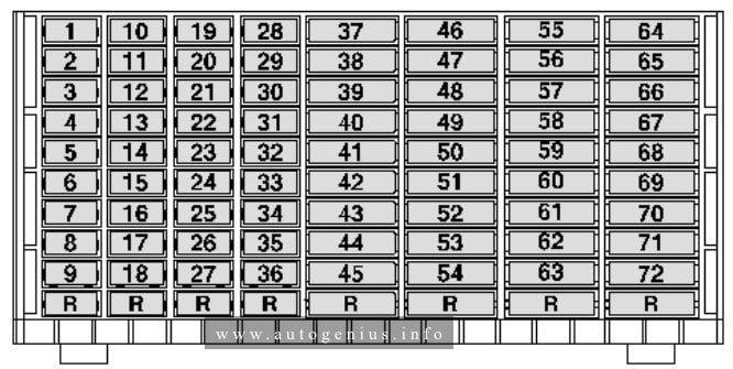
| Fuse |
Current Flow Diagram designation |
Ampere rating [A] |
Function/component |
| 1 |
Fuse 1 on fuse holder C -SC1- |
10 |
ABS cintrol unik -J104-, TCS and ESP button -E256-, Driving program button -E598- |
| 2 |
Fuse 2 on fuse holder C -SC2- |
10 |
Steering column electronics control unit -J527- |
| 3 |
Fuse 3 on fuse holder C -SC3- |
10 |
Reversing switch -F41- |
| 4 |
Fuse 4 on fuse holder C -SC4- |
15 |
Onboard supply control unit -J519- |
| 5 |
Fuse 5 on fuse holder C – SC5- |
5 |
Air mass meter -G70- |
| 6 |
Fuse 6 on fuse holder C -SC6- |
5 |
Trailer detector control unit -J345- |
| 7 |
Fuse 7 on fuse holder C -SC7- |
5 |
Interface for external use |
| 8 |
Fuse 8 on fuse holder C -SC8- |
10 |
Electronic ignition lock -D9- |
| 9 |
Fuse 9 on fuse holder C -SC9- |
10 |
Airbagcontrol unit -J234-, Front passenger side airbag deactivated warning lamp -K145- |
| 10 |
Fuse 10 on fuse holder C -SC10- |
5 |
Engine control unit -J623- |
| 11 |
Fuse 11 on fuse holder C -SC11- |
15 |
Differentral lock control unit -J187- |
| 12 |
Fuse 12 on fuse holder C – SC12- |
10 |
Fuel pump 1 -V276- |
| 13 |
Fuse 13 on fuse holder C -SC13 |
5 |
Exhaust flap valve -N220-, Exhaust gas recirculation cooler change-over calve -N345- |
| 14 |
Fuse 14 on fuse holder C -SC14 |
15 |
Continued coolant circulation pump -V51- |
| 15 |
Fuse 15 on fuse holder C -SC15- |
5 |
Engine control unit -J623- |
| 16 |
Fuse 16 on fuse holder C -SC16- |
10 |
Rear fog light warning lamp -K13-, Rear left fog light bulb -L46-, Rear right fog light bulb -L47- |
| 17 |
Fuse 17 on fuse holder C – SC17- |
5 |
Right tail light bulb -M2-, Right side light bulb -M3- |
| 18 |
Fuse 18 on fuse holder C -SC18- |
5 |
Left side light bulb -M1-, left tail light bulb -M4- |
| 19 |
Fuse 19 on fuse holder C -SC19 |
15 |
Onboard supply control unit -J519- |
| 20 |
Fuse 20 on fuse holder C -SC20- |
15 |
Onboard supply control unit -J519- |
| 21 |
Fuse 21 on fuse holder C -SC21- |
5 |
Onboard supply control unit -J519- |
| 22 |
Fuse 22 on fuse holder C -SC22- |
— |
Vacant |
| 23 |
Fuse 23 on fuse holder C -SC23- |
15 |
Engine control unit -J623- |
| 24 |
Fuse 24 on fuse holder C -SC24 |
10 |
Alarm horn -H12- |
| 25 |
Fuse 25 on fuse holder C -SC25- |
10 |
Heater element fon crancase breather -N79- |
| 26 |
Fuse 26 on fuse holder C -SC26 |
5 |
Right day driving light bulb -L175- |
| 27 |
Fuse 27 on fuse holder C -SC27- |
5 |
Left day driving light bulb -L174- |
| 28 |
Fuse 28 on fuse holder C -SC28- |
15 |
Number plate left light -X4, Number plate right light -X5- |
| 29 |
Fuse 29 on fuse holder C -SC29- |
10 |
Left headlight range control motor -V48- |
| 30 |
Fuse 30 on fuse holder C -SC30- |
10 |
Left main beam bulb -L125- |
| 31 |
Fuse 31 on fuse holder C -Sc31- |
— |
Vacant |
| 32 |
Fuse 32 on fuse holder C -SC32- |
10 |
Right main beam bulb -L126- |
| 33 |
Fuse 33 on fuse holder C -SC33- |
5 |
Mirror adjustment switch -E43- |
| 34 |
Fuse 34 on fuse holder C -Sc34- |
15 |
Vacant |
| 35 |
Fuse 35 on fuse holder C -SC35- |
15 |
Lambda probe 1 upstream of catalytic converter -GX10- |
| 36 |
Fuse 36 on fuse holder C -Sc36- |
5 |
Engine control unit -J623- |
| 37 |
Fuse 37 on fuse holder C -SC37- |
— |
Vacant |
| 38 |
Fuse 38 on fuse holder C -SC38- |
15 |
12V socket -U5- |
| 39 |
Fuse 39 on fuse holder C -SC39- |
25 |
Trailer detector control unit -J345- |
| 40 |
Fuse 40 on fuse holder C -SC40- |
25 |
Trailer detector control unit -J345- |
| 41 |
Fuse 41 on fuse holder C -SC41- |
25 |
Trailer detector control unit -J345- |
| 42 |
Fuse 42 on fuse holder C -SC42- |
15 |
Diagnostic connection -U31-, steering column electronics control unit -J527-, Air conditioning system pressure switch -F129-, Air quality sensor -G238-, differential lock control unit -J187-, transfer box control unit -J646-, dash panel insert -K-, High level brake light bulb -M25-, Brake light switch -F-, Display unit -K40- |
| 43 |
Fuse 41 on fuse holder C – Sc43- |
25 |
Onboard supply control unit -J519- |
| 44 |
Fuse 44 on fuse holder C -SC44- |
30 |
Onboard supply control unit -J519- |
| 45 |
Fuse 45 on fuse holder C -SC45- |
15 |
Diagnostic connection -U31-, Dash panel insert -K-, Steering column electronics control unit -J527-, Air conditioning system control unit -J301-, Climatronic control unit -J255-, Heater/heat output switch -E16- |
| 46 |
Fuse 46 on fuse holder C -SC46- |
25 |
Transfer boc control unit -J646- |
| 47 |
Fuse 47 on fuse holder C -SC47- |
20 |
Onboard supply control unit |
| 48 |
Fuse 48 on fuse holder C -SC48- |
20 |
Driver door control unit -J386- |
| 49 |
Fuse 49 on fuse holder C -SC49- |
20 |
Front passanger door control unit -J387- |
| 50 |
Fuse 50 on fuse holder C -SC50- |
20 |
Rear left door control unit -J388- |
| 51 |
Fuse 51 on fuse holder C -SC51- |
20 |
Rear right door control unit -J389- |
| 52 |
-Fuse 52 on fuse holder C -SC52- |
15 |
Electric socket -U- |
| 53 |
Fuse 53 on fuse holder C -SC53- |
20 |
Left fog light bulb -L22- |
| 54 |
Fuse 54 on fuse holder C -SC54- |
15 |
Cigarette lighter -U1- |
| 55 |
Fuse 55 on fuse holder C -SC55- |
15 |
Right headlight range control motor -V49- |
| 56 |
Fuse 56 on fuse holder C -SC56- |
— |
Vacant |
| 57 |
Fuse 57 on fuse holder C -SC57- |
30 |
Seat heating button, left -E653-, Seat heating button, right – E654-, Seat heating control unit -J882- |
| 58 |
Fuse 58 on fuse holder C -SC58- |
— |
Vacant |
| 59 |
Fuse 59 on fuse holder C -SC59- |
20 |
12V socket -UX3- |
| 60 |
Fuse 60 on fuse holder C -SC60- |
5 |
Trailer detector unit -J345-, Diagnostic connection -U31-, Onboard supply control unit -J519- |
| 61 |
Fuse 61 on fuse holder C -SC61- |
5 |
Trailer detector control unit -J345-, Diagnostic connection -U31-, Onboard supply control unit -J519- |
| 62 |
Fuse 62 on fuse holder C -SC62- |
20 |
Auxiliary heater control unit -J364-, Circulation pump -V55- |
| 63 |
Fuse 63 on fuse holder C -SC63- |
10 |
Load area illumination bulb -M53- |
| 64 |
Fuse 64 on fuse holder C -SC64- |
30 |
Heater/heat output switch -E16-, Climatronic control unit -J255-, Air conditioning system control unit -J301- |
| 65 |
Fuse 65 on fuse holder C -SC65- |
15 |
Engine control unit -J623- |
| 66 |
Fuse 66 on fuse holder C -SC66- |
30 |
Onboard supply control unit -J519- |
| 67 |
Fuse 67 on fuse holder C -SC67- |
30 |
Radio -R-, Control unit with display for radio and navigation system -J503- |
| 68 |
Fuse 68 on fuse holder C -SC68- |
— |
Vacant |
| 69 |
Fuse 69 on fuse holder C -SC69- |
15 |
Interface for external use |
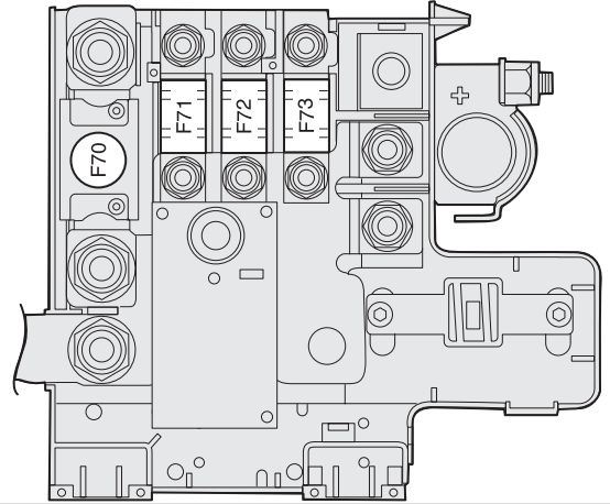
| 70 |
Fuse 70 on fuse holder C -SC70- |
5 |
Interface for external use |
| 71 |
Fuse 71 on fuse holder C -SC71- |
25 |
Interface for external use |
| 72 |
Fuse 72 on fuse holder C -SC72- |
10 |
Interface for external use |