Buick Century (IV; 1978 – 1981) – fuse and relay box diagram
Year of production: 1978, 1979, 1980, 1981
This article covers the Buick Century. It includes fuse box diagrams for the 1978, 1979, 1980 and 1981 models, provides details on the location of the fuse panels inside the vehicle, and explains the function and layout of each fuse.
Fuse box diagram
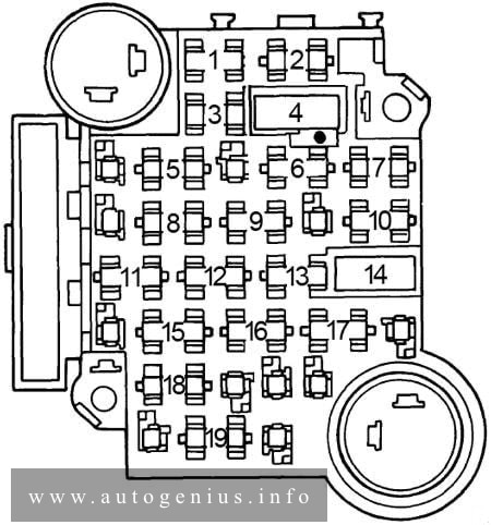
Buick Century (1978 – 1981) – fuse and relay box diagram
Assignment of the fuses in the fuse box diagram
Fuse
[A]
Protected Component
1
5
Instrument illumination and headlight warning
2
20
Electric choke (V6), closed loop
3
—
—
4
30
Circuit breaker: Power windows and roof
5
—
—
6
25
Heater, air conditioning, pulse wipers and deck lid
7
10
Electronic Control Module
8
—
—
9
25
Windshield wiper and washer
10
20
Hazard and stop lights
11
20
Seat belt light and buzzer, heated back light relay, tailgate window release, map light and fuel economy light
12
20
Tail, side marker, parking and license lights, clock radio
13
10
Radio
14
30
Circuit breaker: Power seats, door locks and heated back light
15
20
Turn signal and back-up lights
16
20
Clock, cigar lighter, glove box light, key buzzer, power antenna, clock radio, radio capacitor, dome and sail panel lights, trunk light, reading light, headlight on warning and door locks
17
—
—
18
—
—
19
10
Gauges, cruise control, torque converter clutch and indicator light
Circuit Breaker: Headlight Circuit — A thermo circuit breaker is incorporated in the headlight switch assembly to protect headlight circuits. Windshield Wiper — Integral with windshield wiper motor.
WARNING: Terminal and harness assignments for individual connectors will vary depending on vehicle equipment level, model, and market.
Buick Century (VI; 1997 – 1999) – fuse and relay box diagram
Year of production: 1997, 1998, 1999
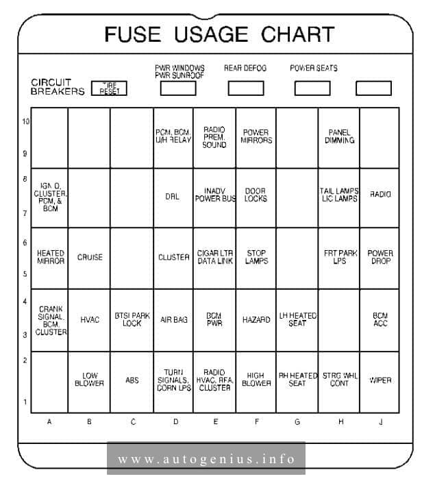
This article covers the Buick Century. It includes fuse box diagrams for the 6th generation 1997 models, provides details on the location of the fuse panels inside the vehicle, and explains the function and layout of each fuse.
Passenger compartment
Fuse box location
The fuse box is located on right side of the instrument panel, behind the cover.
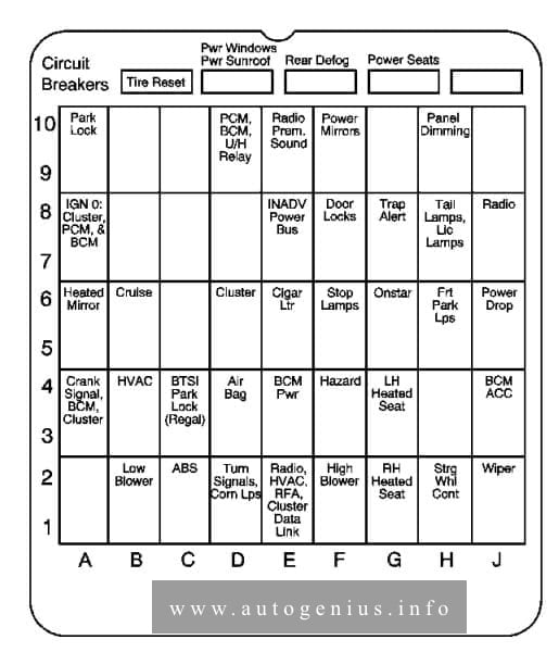
This article covers the Buick Century. It includes fuse box diagrams for the 5th generation 1995 models, provides details on the location of the fuse panels inside the vehicle, and explains the function and layout of each fuse.
Passenger compartment
Fuse box location
The fuse panel is located inside the glove box, on the left side.
Fuse box diagram
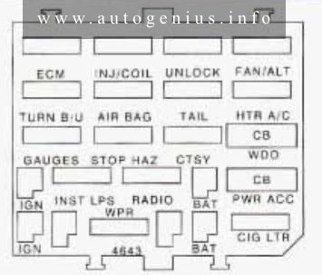
Buick Century (V; 1996) – fuse and relay box diagram – passenger compartment
Assignment of the fuses in the passenger compartment (instrument panel)
Fuse
Usage
ECM
Powertrain Control Module
TNJ/COIL
Fuel Injectors
UNLOCK
Auto Door Locks (Remove this fuse to disable the automatic door unlock)
FAN/ALT
Electric Fan, Starter and Generator, Seq. Fuel Inj (V6), Cruise Control, Anti-Lock Brakes
TURN B/U
Back-up Lamps
AIR BAG
Supplemental Inflatable Restraint (Air Bag System)
TAIL
Taillamps, Parking, Sidemarker, License Plate, Stopflurn Signal
HTR A/C
Heater/Air Conditioner Blower Controls
GAUGES
I/P Cluster, Warning Indicators, Torque Converter Clutch, Audible Warning System, Trunk Release, Brake Warning Indicator, Rear Defog Switch, Remote Keyless Entry, Headlamps, Air Bag System
STOP HAZ
Stop Lamps, Hazard Flashers
CTSY
Interior, Underhood, Courtesy, UP, Trunk Lamps, Door Locks, Horn Relay, Passive Restraint System, Deck Lid Release, Power Antenna Remote Keyless Entry, Vanity Mirror
WDO
Power Windows
INST LPS
Illumination for: I/P, Radio, Pod Lamps, Ashtray, Console Lamp,
Heater and A/C Control, Defog Switch, Headlamp Switch, Power Antenna
RADIO
Radio
PWR ACC*
Seats, Door Locks, Rear Defog, Power Seat Recliner, Rear Window Wiper, Trunk Release
WPR
Windshield Wiper/Washer
CIG LTR
Cigarette Lighter
*Circuit Breaker
WARNING: Terminal and harness assignments for individual connectors will vary depending on vehicle equipment level, model, and market.
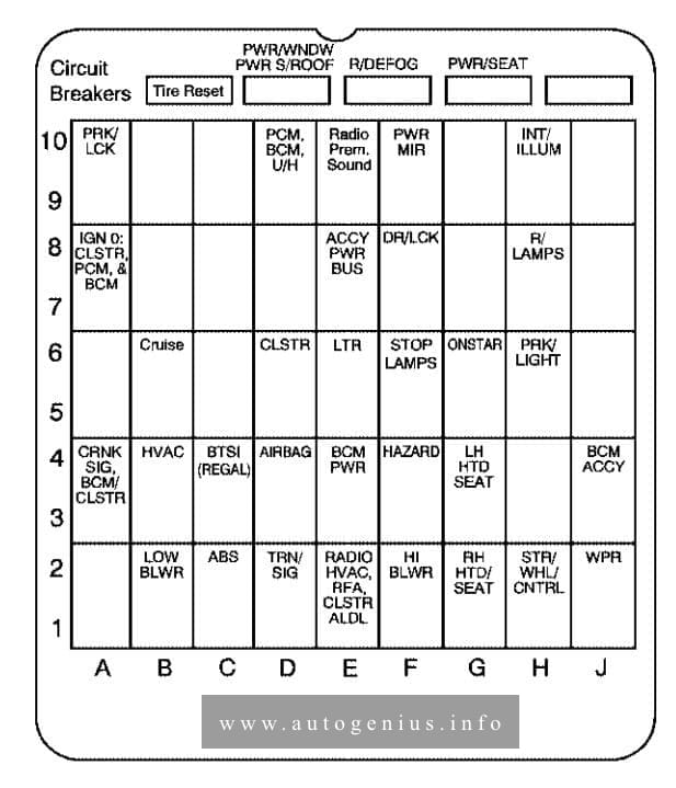
Buick Century (V; 1995) – fuse and relay box diagram
Year of production: 1995
This article covers the Buick Century. It includes fuse box diagrams for the 5th generation 1995 models, provides details on the location of the fuse panels inside the vehicle, and explains the function and layout of each fuse.
Passenger compartment
Fuse box location
The fuse panel is located inside the glove box, on the left side.
Fuse box diagram
Buick Century (V; 1995) – fuse and relay box diagram – passenger compartment
Assignment of the fuses in the passenger compartment (instrument panel)
Fuse
Usage
ECM
Power Train Control Module
TNJ/COIL
Fuel Injectors
UNLOCK
Auto Door Locks (Remove this fuse to disable the automatic door unlock)
FAN/ALT
Electric Fan, Starter and Generator, Seq. Fuel Inj (V6), Cruise Control, Anti-Lock Brakes
TURN B/U
Back-up Lamps
AIR BAG
Supplemental Inflatable Restraint (Air Bag)
TAIL
Tail, Park. Side Marker, License Plate, Stop/Turn Signal
Buick Century (V; 1993) – fuse and relay box diagram
Year of production: 1993
This article covers the Buick Century. It includes fuse box diagrams for the 5th generation 1993 models, provides details on the location of the fuse panels inside the vehicle, and explains the function and layout of each fuse.
Passenger compartment
Fuse box location
The fuse panel is located inside the glove box, on the left side.
Fuse box diagram
Buick Century (V; 1993) – fuse and relay box diagram – passenger compartment
Assignment of the fuses in the passenger compartment (instrument panel)
Buick Century (VI; 2000 – 2001) – fuse box diagram
Year of production: 2000, 2001
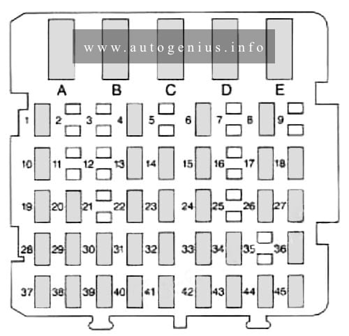
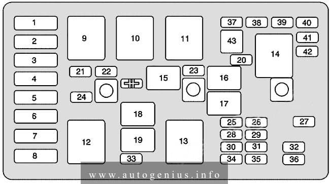
This article covers the Buick Century. It includes fuse box diagrams for the 6th generation 2000 and 2001 models, provides details on the location of the fuse panels inside the vehicle, and explains the function and layout of each fuse.
Passenger compartment
Fuse box location
The fuse box is located on right side of the instrument panel, behind the cover.
Interior Lamps, Retained Accessory Power, Keyless Entry, Data Link, HVAC Head, Cluster, Radio, AUX Power (Power Drop), Cigarette Lighter
8
Ignition Switch, Wipers, Radio, Steering Wheel Controls, Body Control Module, AUX Power (Power Drop), Power Windows, Sunroof, HVAC Controls, DRL, Rear Defog Relay
Mini Relays
Usage
9
Cooling Fan 2
10
Cooling Fan 3
11
Starter Solenoid
12
Cooling Fan 1
13
Ignition Main
14
Air Pump (Optional)
Micro Relays
Usage
15
A/C Clutch
16
Horn
17
Not Used
18
Not Used
19
Fuel Pump
Mini Fuses
Usage
20
Air Pump (Optional)
21
Generator
22
ECM
23
A/C Compressor Clutch
24
Cooling Fan
25
Electronic Ignition
26
Transaxle
Mini Relay
Usage
27
Horn
28
Fuel Injector
29
Oxygen Sensor
30
Engine Emissions
31
Not Used
32
Headlamp (Right)
33
Rear Compartment Release
34
Parking Lamps
35
Fuel Pump
36
Headlamp (Left)
37
Spare
38
Spare
39
Spare
40
Spare
41
Spare
42
Spare
43
Fuse Puller
SYMBOL
Air Conditioner Compressor Clutch Diode
WARNING: Terminal and harness assignments for individual connectors will vary depending on vehicle equipment level, model, and market.
Buick Century (VI; 2002 – 2003) – fuse and relay box diagram
Year of production: 2002, 2003
This article covers the Buick Century. It includes fuse box diagrams for the 6th generation 2002 and 2003 models, provides details on the location of the fuse panels inside the vehicle, and explains the function and layout of each fuse.
Passenger compartment
Fuse box location
The fuse box is located on right side of the instrument panel, behind the cover.
Buick Century (VI; 2004 – 2005) – fuse and relaybox diagram
Year of production: 2004, 2005
This article covers the Buick Century. It includes fuse box diagrams for the 6th generation 2004 and 2005 models, provides details on the location of the fuse panels inside the vehicle, and explains the function and layout of each fuse.
Passenger compartment
Fuse box location
The fuse box is located on right side of the instrument panel, behind the cover.