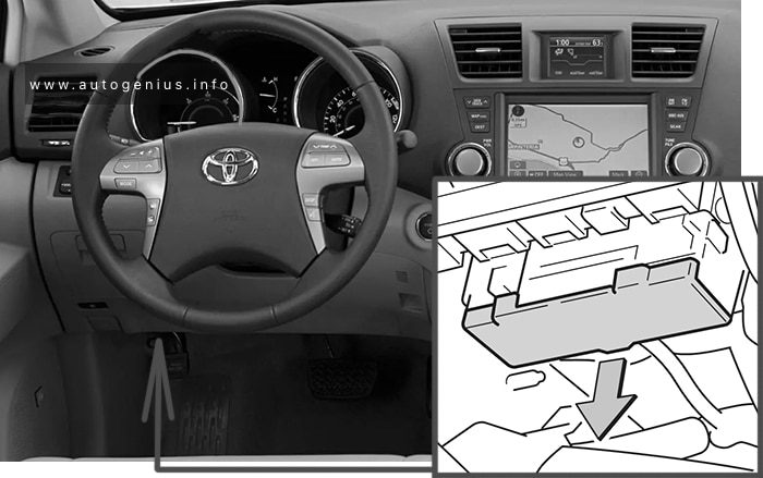
Toyota Highlander (XU40; 2011 – 2013) – fuse box diagram
Year of production: 2011, 2012, 2013
The Toyota Highlander XU40 crossover represents the 2nd generation of the Toyota Highlander model range. Years of production: 2007, 2008, 2009, 2010, 2011, 2012, 2013, 2014. During this time, the model has been restyled. In our material you can find a description of fuses and relays Toyota Highlander 2 with box diagrams and their locations.
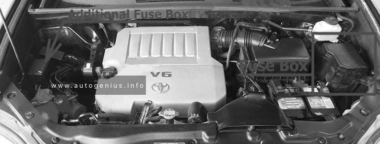
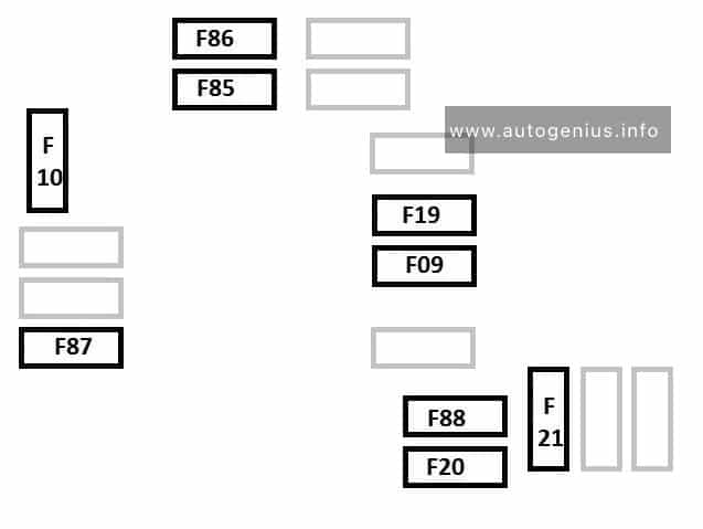
Engine compartment
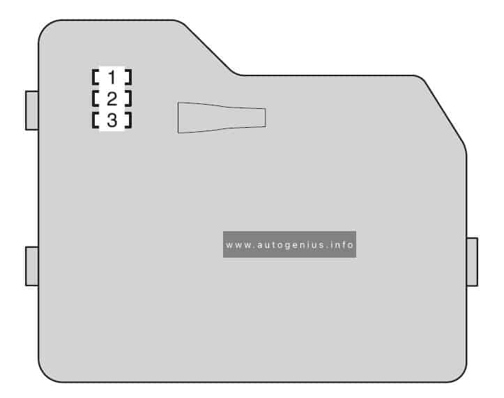
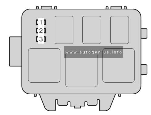
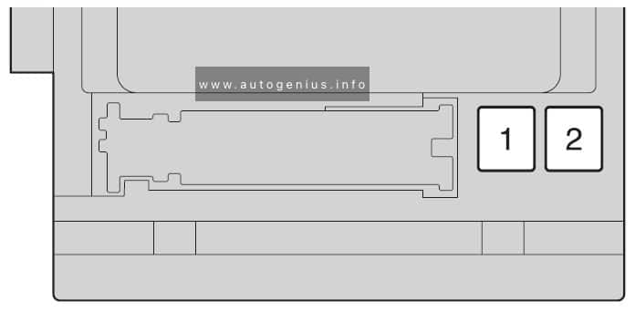
Fuse box location
There are 2 fuse and relay boxes under the hood.
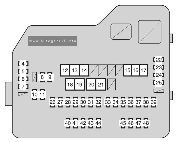
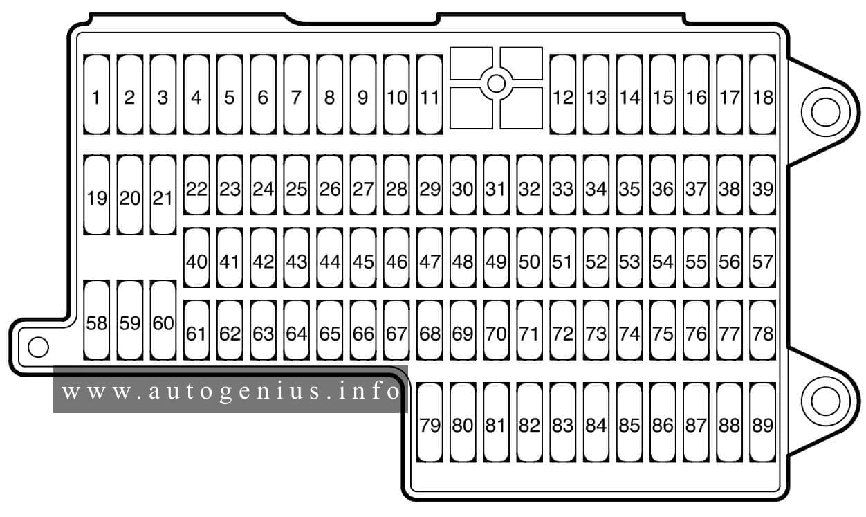
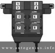
It is located in the engine compartment (left-side)
Multiport fuel injection system/sequential multiport fuel injection system
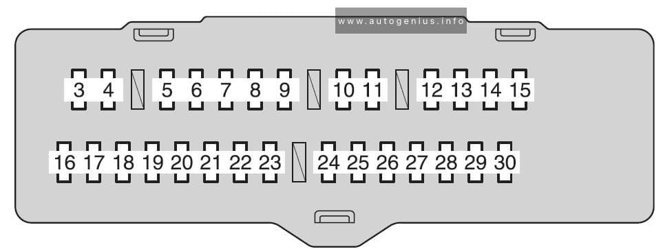
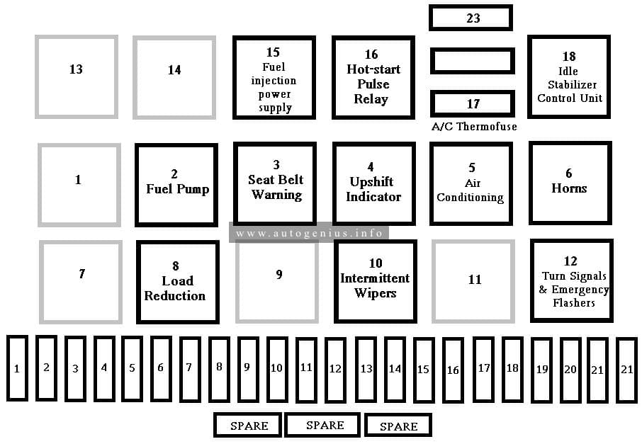
12
HTR
50
Air conditioning system
13
VSC NO.1
50
Enhanced vehicle stability control system
14
FAN MAIN
50
Electric cooling fan
15
VSC NO.2
30
Enhanced vehicle stability control system
16
PTC NO.1
50
Air conditioning system
17
PTC NO.2
30
Air conditioning system
18
PTC NO.3
30
Air conditioning system
19
RR CLR
40
Air conditioning system
20
RR DEF
30
Rear window defogger
21
PBD
30
Power back door
22
ALT
140
MIR HTR, PWR OUTLET, DOOR NO.1, HTR, RR DEF, FAN MAIN, VSC NO.1, PTC NO.1, RR CLR, PTC NO.2, PTC NO.3, VSC NO.2, PBD
23
EPS
80
Electric power steering
24
ST
30
Starting system
25
CRT
10
Rear seat entertainment system
26
RADIO NO.1
158
Audio system
27
ECU-B NO.1
10
Steering sensor, gauges and meters, clock, main body ECU,
wireless remote control, smart key system, power back door, multiinformation display, front passenger occupant classification system
28
DOME
10
Vanity lights, personal lights, interior light, gauges and meters, engine switch light, door courtesy lights
This article focuses onVolkswagen Phaeton, manufactured between 2002 and 2016. It includes fuse box diagrams for Volkswagen Phaeton models from 2002 through 2006, details on the location of the fuse panels within the vehicle, and information about the function of each fuse (fuse layout).
Relays and Fuses
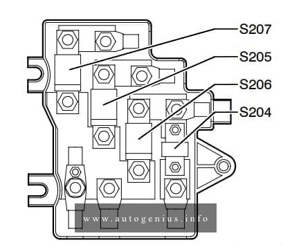
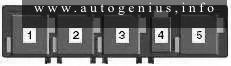
Main fuse box in luggage compartment, left – Main Fuses
Fuse box diagram
Volkswagen Phaeton (2002 – 2006)- fuse and relay box diagram – main fuse box – luggage compartment (left)
Assignment of thefuses in the luggage comparment
Number
Ref. in wiring diagram
Amps
Function/Component
Terminal
1
S204 – Fuse -1- (30)
100
A18 – Windshield Heating Voltage Converter
30
2
S205 – Fuse -2- (30)
150
TV28- Wire junction 3 for terminal 30,
Thermofuses: SE1, SE2, SE3, SE4, SE5, SE6, SE7 Fuses: SB5, SB7 to SB18, SB27 to SB36, SD11, SD23, SD24, SD26,
J329- Voltage Supply Terminal 15 (B+) Relay
J680- Power Supply Relay 1 (terminal 75)
30
3
S206 – Fuse -3- (30)
300
Fuses: SC3, SC6, SC8 to SC16, SC23 to SC27, SC41 to SC47
C – Generator (GEN)
30
4
S207 – Fuse -4- (30)
—
Open
30
Fuse box under instrument panel, left – Fuses “SB”
Volkswagen Rabbit GTI (A1, Type 17; 1974 – 1984) – fuse and relay box diagram
Year of production: 1974, 1975, 1976, 1977, 1978, 1979, 1980, 1981, 1982, 1983, 1984
This article covers the Volkswagen Rabbit, manufactured from 1974 to 1984. It includes fuse box diagrams for the 1974 to 1984 models, provides details on the location of the fuse panels inside the vehicle, and explains the function and layout of each fuse and relay.
Chevrolet Equinox (2010 – 2017) – fuse and relay box diagram
Year of production: 2010, 2011, 2012, 2013, 2014, 2015, 2016, 2017
This article covers the second-generation Chevrolet Equinox, produced from 2010 to 2017. It provides fuse box diagrams for the 2010 through 2017 models, outlines the locations of the fuse panels within the vehicle, and explains the purpose and layout of each fuse and relay.
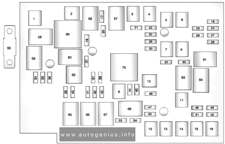
Engine compartment
Fuse box diagram
Chevrolet Equinox (2010 – 2017) – fuses and relay box diagram – engine compartment
Assignment of the fuses and relay in the engine compartment
№
Usage
1
Cool Fan 1
2
Cool Fan 2
3
Brake Booster
4
Power Windows -Right
5
Memory Seat Module
6
Power Seat – Left
7
Instrument Panel Fuse Block 1
8
Rear Defogger
9
Starter
10
AIR Pump Motor
11
Instrument Panel Fuse Block 2
12
Sunroof
13
Antilock Brake System Pump
14
Instrument Panel Fuse Block 3
15
Power Windows – Left
16
Antilock Brake System Module
17
Transmission Control Module Battery
18
Trailer Parking Light
19
AIR Pump Solenoid
20
Engine Control Module Battery
21
Canister Vent
22
Trailer Left Side (If Equipped)
23
Lift Gate Module
24
Power Lumbar
25
Trailer Right Side (If Equipped)
26
Rear Accessory Power Outlet
27
Memory Mirror Module
28
Regulated Voltage Control Battery Sensor
29
Front Wiper
30
Rear Wiper
31
Air Conditioning Compressor
32
Rear Latch
33
Heated Mirrors
34
Horn
35
Right High-Beam Headlamp
36
Left High-Beam Headlamp
37
Ignition Even Coil
38
Ignition Odd Coil
39
Windshield Washer
40
Front Fog Lamps
41
Post Catalytic Converter Oxygen Sensor
42
Engine Control Module
43
Pre-Catalytic Converter Oxygen Sensor
44
Transmission Control Module
45
Mirror
46
Fuel System Control Module Ignition
47
Spare
48
Rear Drive Module
49
Lift Gate Module Logic
50
Instrument Panel Fuse Block Ignition
51
Heated Seat- Front
52
Fuel System Control Module
53
Engine Control Module
54
Rear Vision Camera
55
Electric Power Steering
56
AIR Pump Solenoid
57
Brake Booster
58
Cooling Fan Low
59
Headlamp High Beam
60
Cooling Fan Control
61
Wiper On/Off Control
62
Air Conditioning Compressor
63
Rear Defogger
64
Wiper Speed
65
Fog Lamp
66
Engine Control
67
Starter
68
Run/Crank
69
Cooling Fan High
70
AIR Pump Motor
77
Power Seat – Right
78
Passenger Power Lumber
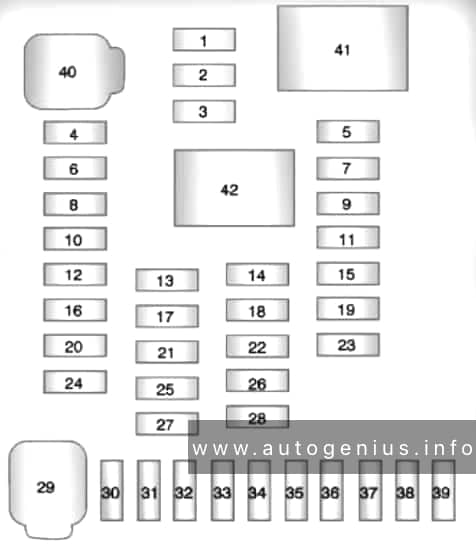
Instrument panel fuse block
Fuse Box Location
The instrument panel fuse block is located on the passenger side panel of the center console.
Fuse box diagram
Chevrolet Equinox (2010 – 2017) – fuses and relay box diagram – passenger compartment
Assignment of the fuses and relay in the instrument panel
№
Usage
1
Steering Wheel Dimming
2
Spare
3
Spare
4
Body Control Module 1
5
Infotainment
6
Body Control Module 7
7
Noise Control Module
8
Body Control Module 4
9
Radio
10
Spare
11
Rear Parking Assist Module
12
Heater, Ventilation, and Air Conditioning Battery
13
Auxiliary Power Front
14
Heater, Ventilation and Air Conditioning Ignition
15
Display
16
Body Control Module 5
17
Auxiliary Power Rear
18
Instrument Panel Ignition
19
Universal Garage Door Opener
20
Body Control Module 6
21
Spare
22
Sensing and Diagnostic Module Ignition
23
Front Camera
24
Spare
25
Transmission Gear Shift Position Indicator
26
Spare
27
Spare
28
Spare
29
Front Blower Motor
30
Body Control Module 3
31
Amplifier
32
Discrete Logic Ignition Switch
33
Communications Integration Module
34
Body Control Module 2
35
Sensing and Diagnostic Module Battery
36
Data Link Connection
37
Instrument Panel Battery
38
Passenger Sensing System Module
39
Spare
40
Body Control Module 8
41
Logistic Relay (If Equipped)
42
Retained Accessory Power Relay
WARNING: Terminal and harness assignments for individual connectors will vary depending on vehicle equipment level, model, and market.
Chevrolet Equinox (2005) – fuse and relay box diagram
Year of production: 2005
This article focuses on the first-generation Chevrolet Equinox, manufactured between 2005 and 2009. It includes fuse box diagrams for the 2005 models, details the locations of the fuse panels within the vehicle, and provides information on the function and layout of each fuse and relay.
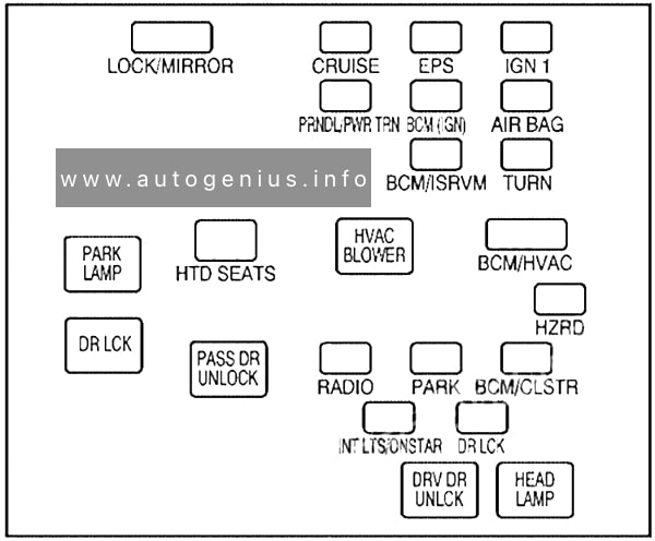
Passenger compartment
Fuse Box Location
The fuse box is located under the dashboard on the passenger’s side of the center console, behind the cover.
Fuse Box Diagram
Chevrolet Equinox (2005) – fuses and relay box diagram – passenger compartment
Assignment of the fuses and relays in the passenger compartment
Name
Description
LOCK/MIRROR
Door Lock, Power Mirror
CRUISE
Cruise Control System
EPS
Electric Power Steering
IGN 1
2005: Ignition System
2006: Switches, Instrument Panel Cluster
PRNDL/ PWR TRN
PRNDL/Powertrain
BCM (IGN)
Body Control Module
AIRBAG
Airbag System
BCM/ISRVM
2005: Inside Rearview Mirror
2006: Body Control Module, Inside Rearview Mirror
TURN
Turn Signals
HTD SEATS
Heated Seats
BCM/HVAC
Body Control Module, Heating, Ventilation and Air Conditioning
HZRD
Hazard Warning Flashers
RADIO
Radio
PARK
Parking Lamps
BCM/CLSTR
2005: Instrument Panel Cluster
2006: Body Control Module, Instrument Panel Cluster
INT LTS/ ONSTAR
Interior Lights/OnStar
DR LCK
Door Locks
Relays
PARK LAMP
Parking Lamps Relay
HVAC BLOWER
Heating, Ventilation and Air Conditioning Blower Motor
DR LCK
Door Locks Relay
PASS DR UNLOCK
Passenger Door Unlock Relay
DRV DR UNLCK
Driver Door Unlock Relay
HEAD LAMP
Headlamps
Engine Compartment
Fuse Box Diagram
Chevrolet Equinox (2005) – fuses and relay box diagram – engine compartment
Assignment of the fuses and relays in the engine compartment
Name
Description
HTD SEATS
Heated Seats
HVAC BLOWER
Heating, Ventilation, Air Conditioning Blower Control
PREM AUD
Premium Audio System, Amplifier
ABS PWR
Anti-lock Brake System
RR WIPER
Rear Window Wiper
FRT WIPER
Front Window Wiper
SUNROOF
Sunroof
ETC
Electronic Throttle Control
PWR WDW
Power Windows
A/C CLUTCH
Air Conditioning Clutch
EMISS
Emissions
ENG IGN
Engine Ignition
CIGAR
Cigarette Lighter
LH HDLP
Left Headlamp
COOL FAN HI
Cooling Fan High
ECM/TCM
2005: Body Control Module
2006: Engine Control Module, Transaxle Control Module
AUX OUTLETS /
AUX1 OUTLET
Accessory Power Outlets
FUSE PULLER
Fuse Puller
INJ
Fuel Injectors
PWR TRAIN
Powertrain
FUEL PUMP
Fuel Pump
A/C DIODE
Air Conditioning Diode
TRAILER
2006: Trailer Lighting
AUX 2/CARGO
2005: Accessory Power Outlet 2, Cargo Outlet
BRAKE
Brake System
RH HDLP
Right Headlamp
HORN
Horn
BACKUP
Back-up Lamps
BATT FEED
Battery
ABS
Anti-lock Brake System
COOL FAN LO
Cooling Fan Low
RR DEFOG
Rear Window Defogger
START
2005: Ignition
ABS
Anti-lock Brake System
FOG LP
Fog Lamps
IGN
Ignition Switch
CB POWER SEATS
Power Seats (Circuit Breaker)
Relays
ENG MAIN
Engine Relay
RR WIPER
Rear Window Wiper Relay
FRT WIPER
Front Window Wiper Relay
PWR WDW
Power Windows Relay
COOL FAN HI
Cooling Fan High Relay
WIPER SYSTEM
Wiper System Relay
HORN
Horn Relay
DRL
Daytime Running Lamps Relay
FUEL PUMP
Fuel Pump Relay
STARTER RELAY
Starter Relay
REAR DEFOG
Rear Window Defogger Relay
FOG LP
Fog Lamp Relay
COOL FAN LO
Cooling Fan Low Relay
A/C CLUTCH
Air Conditioning Clutch Relay
WARNING: Terminal and harness assignments for individual connectors will vary depending on vehicle equipment level, model, and market.
Year of production: 2013, 2014, 2015, 2016, 2017, 2018
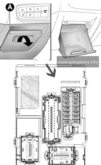
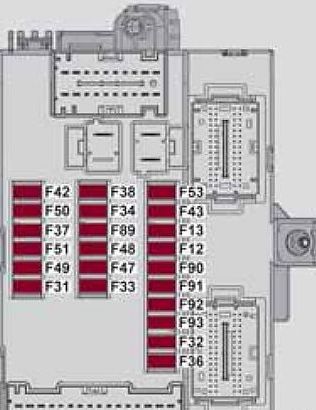
The Alfa Romeo MiTo (Series 955) was first introduced in 2008 and underwent a restyling in 2014. Although there were no significant external changes, a new trim for the headlight surround and a chrome grille were added. Internal changes varied depending on the configuration and year of manufacture. This article focuses on the fuse and relay boxes of the Alfa Romeo MiTo from 2009 to 2018, providing diagrams and locations.
Front roof light, Luggage compartment roof light, Sun visor courtesy light, Door puddle lights, Glove compartment light
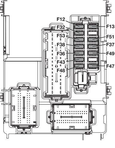
F32
5
Radio, sound system setup system (for versions/markets, where provided), Uconnect ™ 5″ radio (for versions/markets, where provided), climate control system control unit, alarm system control unit, volumetric system control unit, EOBD external diagnosis socket, tyre pressure monitoring control unit
F36
10
Instrument panel, brake light on switch
F37
5
Door lock motor on doors, Safe Lock motor on doors, Tailgate unlocking motor
F38
15
Windscreen/rear window washer pump
F43
20
Electric window motor complete with control unit (driver side door)
F47
20
Electric window motor complete with control unit (passenger side door)
F48
20
Parking sensor control unit, Tire pressure control unit, Rain sensor, automatic headlight switch on the interior rearview mirrors, electrochromic (convex) interior rearview mirror, radio navigation (backlight), LED on the display indicating that the seat belts are fastened on the interior rearview mirror, illumination of controls (center dashboard, driver side dashboard, steering wheel controls, Blue & Me controls), front seat heating switches, volumetric alarm control unit, electric sunroof control, PND connector on the dashboard
F49
5
Clutch activation switch, brake light switch, relay switch coils on engine fuse box control unit, control system on internal climate control/heater unit, flow meter, water presence in diesel sensor, radio, radio setup system (for versions/markets, where provided)
F51
5
nstrument pane
F51
5
* – For versions/markets, where provided
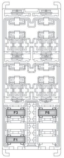
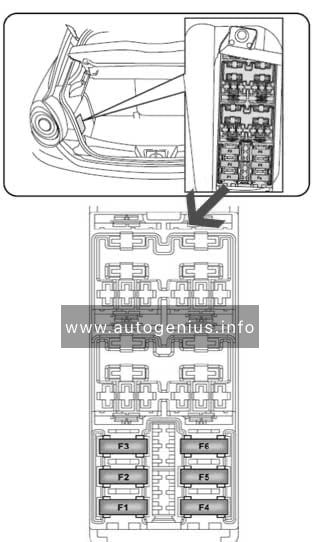
Luggage compartment fuse box
Located on the left under the casing.
Alfa Romeo MiTo FL – fuse box – luggage
Device protected
Fuse
Ampere rating [A]
Bose HI-FI amplifier control unit
F4
15A
Bassbox subwoofer in the spare wheel compartment
F5
10A
Heated front left and right seats
F6
15A
Electric hatch opening system
F1
20A
Wiring fuses
F2
–
Trunk power socket
F3
15A
WARNING: Terminal and harness assignments for individual connectors will vary depending on vehicle equipment level, model, and market.
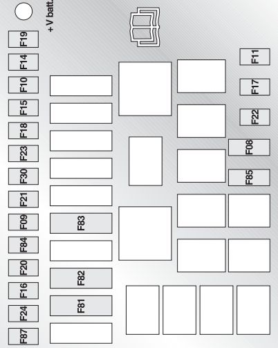
Year of production: 2008, 2009, 2010, 2011, 2012, 2013
The Alfa Romeo MiTo (Series 955) was first introduced in 2008 and underwent a restyling in 2014. Although there were no significant external changes, a new trim for the headlight surround and a chrome grille were added. Internal changes varied depending on the configuration and year of manufacture. This article focuses on the fuse and relay boxes of the Alfa Romeo MiTo from 2009 to 2018, providing diagrams and locations.
Front courtesy light, luggage compartment light, Sun visor courtesy light, Door lights, Glove compartment light
F32
5
Dashboard
Consumers
Fuse
Ampere rating [A]
Location
Passenger compartment fan
F08
30
Engine compartment
Headlight washer pump
F09
20
Engine compartment
Two-tone horn
F10
15
Engine compartment
Waste gate solenoid, Shut off solenoid, Canister solenoid, Lambda Sensor Heater, VGT solenoid, EGR cooling bypass solenoid, Swirl solenoid, Throttle solenoid, Glow plug preheating control unit
F11
10
Engine compartment
Headlight alignment adjustment system
f13
7,5
Dashboard
Additional heater (PTC 1)
F15
30
Engine compartment
Engine management control unit
F16
5
Engine compartment
Engine management control unit (power supply)
F17
10
Engine compartment
Control system relay coil, Engine management control unit (1.4 versions), Engine cooling system remote control switch coil (300W+300W)
F18
5
Engine compartment
Air conditioning compressor
F19
7,5
Engine compartment
Heated rear windscreen, demisting system
F20
30
Engine compartment
Fuel pump on tank
F21
15
Engine compartment
Engine management system main loads (1.4 versions)
F22
10
Engine compartment
Engine management system main loads (1.6 JTDM versions)
F22
20
Engine compartment
Braking system control unit (control unit and solenoid unit)
F23
20
Engine compartment
Electric steering control unit (power supply + Key), Brake system control unit (power supply + Key), Yaw sensor on tunnel
F24
5
Engine compartment
INT/A key exhaust relay coils on engine fuse box
F31
5
Dashboard
Radio, Blue&MeTM control unit, Climate control unit, Alarm control unit, Volume sensing system control unit, EOBD external diagnostic socket, Tyre pressure detection control unit
F36
10
Dashboard
Instrument panel, Brake light switch, Gas discharge headlights management system
F37
5
Dashboard
Door lock motor on door, Safe Lock motor on doors, Tailgate unlocking motor
F38
15
Dashboard
Windscreen / rearscreen washer pump
F43
20
Dashboard
Electric window motor complete with control unit (driver-side door)
F47
20
Dashboard
Electric window motor complete with control unit (passenger-side door)
F48
20
Dashboard
Parking sensors control unit, Tyre pressure detection control unit, Rain/dusk sensor on rear-view mirror, Electro-chrome sensor on rear-view mirror, Seat belts fastened warning light display on rear-view mirror, Control panel illumination (Central control panel, Driver-side control panel, Steering wheel control panel, Blue&MeTM control panel), Front seat heating pad activation switch, Alarm system volume-sensing sensors control unit, Electric sunroof control unit, PND socket on dashboard
F49
5
Dashboard
Air Bag system control unit
F50
7,5
Dashboard
Clutch switch, Brake light switch, relay coils on engine fuse box, Control system on internal heater/air conditioning unit, Blue&MeTM control unit, Radio wiring, Air flow meter, Water in diesel fuel sensor
F51
5
Dashboard
Instrument panel
F53
5
Dashboard
Bose HI-FI system amplifier control unit
F4
15
Luggage
Bassbox subwoofer in spare wheel compartment
F5
10
Luggage
Left and right front seat heater
F6
15
Luggage
Electric sunroof opening system
F1
20
Luggage
Fuse wiring
F2
—
Luggage
Luggage compartment power socket
F3
15
Luggage
Passenger compartment fan
F83
40
Engine compartment
Power socket on tunnel
F85
15
Engine compartment
Passenger/driver-side door mirror demister, Demister on front jets, Heated windscreen relay coil
F87
7,5
Engine compartment
WARNING: Terminal and harness assignments for individual connectors will vary depending on vehicle equipment level, model, and market.
Year of production: 2013, 2014, 2015, 2016, 2017, 2018, 2019, 2020
Alfa Romeo Giulietta is a compact hatchback produced since 2010. It was created as the older model of the Alfa Romeo MiTo. Our material will help owners of Alfa Romeo Giulietta 2011, 2012, 2013, 2014, 2015, 2016, 2017, 2018, 2019, 2020 (During this time, the model underwent a facelift several times.) in finding and replacing fuses and relays. We will also show fuse box diagrams and locations. NOte the cigarette lighter fuse.
There are 3 main fuse boxes in this model. One is in the engine compartment, the second is in the passenger compartment under the dashboard, and the third is in the luggage compartment.
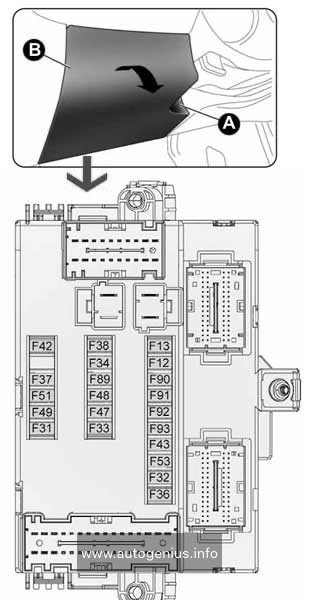
Fiat Ducato (III FL; 2014 – 2019) – fuse and relay box diagram
Year of production: 2014, 2015, 2016, 2017, 2018, 2019
This article covers the third-generation (3rd generation), produced from 2014 to present. It includes fuse box diagrams for the 2014, 2015, 2016, 2017, 2018 and 2019 models, provides details on the location of the fuse panels inside the vehicle, and explains the function and layout of each fuse.
Passenger compartment
Fuse box diagram
Fiat Ducato (III FL; 2014 – 2019) – fuse and relay box diagram – passenger compartment (dashboard)
Assignment of the fuses in the passenger compartment (dashboard)
№
Ampere rating [A]
Device protected
F12
7,5
Right dipped beam headlight
F13
7,5
Left dipped headlight
F31
5
Engine compartment control unit relay, dashboard control unit relay (+key)
F32
7,5
Lighting of roof lights in the passenger compartment (+battery)
F33
7,5
Battery monitoring sensor for Start&Stop versions (+battery)
F34
7,5
Minibus interior lights (emergency)
F35
7,5
Reversing lights, sevotronic control unit, Water in diesel fuel filter sensor, (+key)
F36
10
Radio, climate control, alarm, tachograph, battery disconnecting control unit, Webasto timer (+battery
F37
7,5
Brake light control (main), third brake light instrument panel (+key
F38
20
Door lock (+battery
F43
20
Windscreen wiper (+key)
F47
20
Driver’s side electric window
F48
20
Passenger side electric window
F49
5
Parking sensor control unit, radio, steering wheel controls, central control panel, left control panel, auxiliary panel, battery disconnecting control unit (+key
F51
5
Climate control, power steering control unit, reverse lights, diesel filter water sensor, flow meter, tachograph (+key)
F53
7,5
Instrument panel (+battery)
F89
—
—
F90
7,5
Left main beam headlight
F91
7,5
Right main beam headlight
F92
7,5
Left fog light
F93
7,5
Right fog light
Passenger compartment (optional fuse box)
Fuse box location
Optional fuse box on the right central post (where provided)
Fuse box diagram
Fiat Ducato (III FL; 2014 – 2019) – fuse and relay box diagram – passenger compartment (optional)
Assignment of the fuses in the passenger compartment (optional fuse box)
№
Ampere rating [A]
Device protected
F54
—
—
F55
15
Heated seats
F56
15
Rear passenger power socket
F57
10
Additional heater under the seat
F58
10
Left heated rear window
F59
7,5
Right heated rear window
F60
—
—
F61
—
—
F62
—
—
F63
10
Additional passenger heater control
F64
—
—
F65
30
Additional passenger heater fan
Engine compartment
Fuse box diagram
Fiat Ducato (III FL; 2014 – 2019) – fuse and relay box diagram – engine compartment
Assignment of the fuses in the engine compartment
№
Ampere rating [A]
Device protected
F03
30
Ignition switch (+battery)
F04
40
Heated filter
F05
20/50
Vaporiser for Puma engine/Passenger compartment ventilation with Webasto, robotised gearbox pump (+battery)
F06
40/60
Engine cooling high speed fan (+battery)
F07
40/50/60
Engine cooling low speed fan (+battery)
F08
40
Passenger compartment fan (+key
F09
15
Rear power socket (+battery)
F10
15
Horn
F14
15
Power socket (+battery)
F15
15
Cigar lighter (+battery)
F18
7,5
Powertrain Control Module, robotised gearbox control unit (+battery)
F19
7,5
Air conditioning compressor
F20
30
Windscreen wiper
F24
7,5
Auxiliary control panel for mirror movement and folding (+key)
F30
15
Mirrors demisting
WARNING: Terminal and harness assignments for individual connectors will vary depending on vehicle equipment level, model, and market.
This article focuses on the seventh-generation Volkswagen Passat (B7), produced between 2011 and 2015. It includes fuse box diagrams for the 2011–2015 Passat models, explains where the fuse panels are located inside the vehicle, and provides details on the function and layout of each fuse and relay
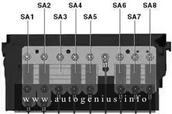
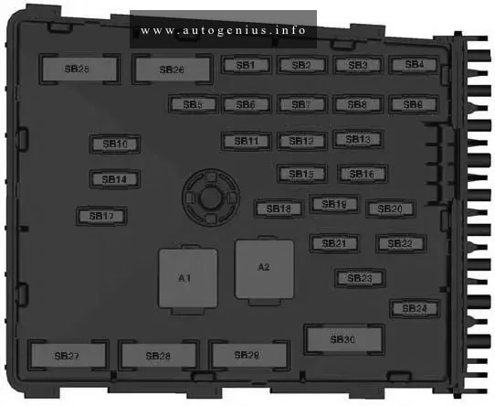
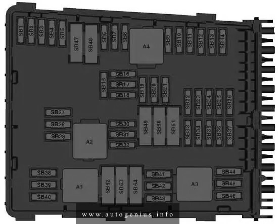
1 – Pre-Fuse box (Fuse holder A -SA-); 2 – Relay carrier under electronics box; 3 – Terminal 30 wiring junction; 4 – Heated windscreen relay; In plenum chamber next to engine control unit; 5 – Fuses on left under dash panel; 6 – Fuse holder on the right side edge of the instrument panel (Fuse holder D -SD-); 7 – Relays on onboard supply control unit; 8 – Fuses in the luggage compartment (Fuse holder F -SF-); There are additional fuses above the vehicle battery behind the panel on the left side of the luggage Compartment. 9 – Fuse 2 (30) -S205- (60 A); 10 – Fuse holder on the left side edge of the instrument panel (Fuse holder C -SC-); 11 – Relay carrier 1 on left under dash panel; 12 – Relay carrier 2 on left under dash panel; 13 – Relay carrier under electronics box; 14 – Fuse box in the Engine compartment (Fuse holder B -SB-)
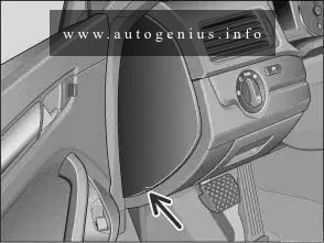
Passenger compartment
Fuse box location
Fuse Box in the Left side edge of the instrument panel
Assignment of the fuses in the passenger compartment (instrument panel – left side)
№
Amp
Function/component
1
10
High-pressure sender -G65-
Air quality sensor -G238-
Oil level and oil temperature sender -G266-
Fresh air blower relay -J13-
DC./AC converter with socket, 12 V – 230 V -U13-
Automatic anti-dazzle interior mirror -Y7-
Heated rear left seat switch with regulator -E128-
Heated rear right seat switch with regulator -E129-
2
5
Light switch -E1-
TCS and ESP button -E256-
Auto-hold button -E540-
ABS control unit -J104-
Power steering control unit -J500-
Control unit for electromechanical parking brake -J540-
3
10
Current supply relay -J16-
Heater element for crankcase breather -N79-
Gas injection valve 1-N366- Gas injection valve 2 -N367-
Gas injection valve 3 -N368-
Gas injection valve 4 -N369-
4
10
Rear roller blind switch -E149-
Start/Stop operation button -E693-
Electronically controlled damping control unit -J250-
Adaptive cruise control unit -J428-
Parking aid control unit -J446-
Trailer detector control unit -J345-
Park assist steering control unit -J791-
Front camera for driver assist systems -R242-
Diagnostic connection -U31-
5
10
Headlight range control regulator -E102-
Left headlight range control motor -V48-
Right headlight range control motor -V49-
Front left headlight (Only right-hand drive models) -MX1-
6
10
All-wheel drive control unit -J492-
7
5
Control unit in dash panel insert -J285-
Data bus diagnostic interface -J533-
8
10
Front right headlight -MX2- (Only right-hand drive models)
9
10
Airbag control unit -J234-
Front passenger side airbag deactivated warning lamp -K145-
10
10
Air mass meter -G70-
Voltage stabiliser -J532-
Fuel pump control unit -J538-
Engine control unit -J623-
Terminal 50 voltage supply relay -J682-
Voltage supply relay 2 -J710-
Starter relay 1 -J906-
Starter relay 2 -J907-
11
5
Warning buzzer pedal switch on front passenger side -F349- (Only applicable to special vehicles)
12
20
Convenience system central control unit -J393-
Front passenger door control unit (Only CC) -J387-
Rear passenger side door control unit (Only CC) -J927-
13
10
Light switch -E1-Selector lever -E313-
ABS control unit -J 104-
Handbrake warning lamp -K139-
Diagnostic connection -U31-
ABS control unit -J104- T38/15
Rain and light sensor -G397-
Heated rear window relay -J9-
Heated windscreen relay -J47-
Climatronic control unit -J255-
Air conditioning system control unit -J301-
Reversing camera system control unit -J772-
Control unit for terminal control and engine start -J942-
Remote control receiver for auxiliary coolant heater -R149-
Tyre Pressure Monitoring System control unit -J502-
16
10
Electronic ignition lock -D9-
Electronic steering column lock control unit -J764-
Control unit for terminal control and engine start -J942-
17
15
Driver door control unit (Only CC) -J386-
Rear driver side door control unit (Only CC) -J926-
Not used (from May 2012)
18
3A
Onboard supply control unit -J519-
Voltage stabiliser -J532-
Engine control unit -J623-
Voltage supply relay 2 -J710-
19
–
Not used
20
–
Not used
21
10
Rear roller blind control unit -J262-
22
20
Control unit for electromechanical parking brake -J540-
23
15
Trailer detector control unit -J345-
Electronically controlled damping control unit (Only right-hand drive models) -J250-
24
20
Control unit for electromechanical parking brake -J540-
25
5 (Only models with emergency call module)
15 (Only models with trailer socket)
30 (Only right-hand drive models)
Emergency assistance call button -E276-
Trailer detector control unit -J345-
Sunroof roller blind control unit (Only right-hand drive models) -J394-
26
20
Onboard supply control unit -J519-
27
15 (Only models with a petrol engine)
20 (Only models with a diesel engine)
Fuel pump control unit (Only models with a petrol engine) -J538-
Fuel pump relay (Only models with a diesel engine) -J17-
Electric fuel pump 2 relay (Only models with a diesel engine) -J49-
28
30
Driver door control unit (Only left-hand drive models) -J386-
Rear driver side door control unit (Only left-hand drive models) -J926-
Front passenger door control unit (Only right-hand drive models) -J387-
Rear passenger side door control unit (Only right-hand drive models) -J927-
29
20
Heated rear seats control unit -J786-
30
20 (Only saloon)
30 (Only estate)
Sliding sunroof adjustment control unit -J245-
31
30
DC/AC converter with socket, 12 V-230 V -U13-
32
30
Heated rear window relay -J9-
33
30
Headlight washer system relay -J39-
34
25
Heated front seats control unit -J774-
35
15 (Only right-hand drive models)
Rear lid control unit (Only right-hand drive models) -J605-
Driver seat lumbar support adjustment switch (Only left-hand drive models) -E176- (from May 2012)
36
15
Driver seat lumbar support adjustment switch -E176-
Trailer voltage supply relay -J941- (from May 2012)
Trailer detector control unit (Only left-hand drive models) -J345-
Rear lid control unit 2 (Only right-hand drive models) -J756-
38
40 (Only models with auxiliary heating)
Fresh air blower relay (Only models with Climatic) -J13-
Fresh air blower control unit (Only models with Climatronic) -J126-
39
5
Selector lever -E313-
Reversing light switch -F4-
Mechatronic unit for dual clutch gearbox -J743-
40
20
Onboard supply control unit -J519-
Rear window wiper motor -V12-
Windscreen and rear window washer pump -V59-
41
20
Onboard supply control unit -J519-
Cigarette lighter -U1-
Rear cigarette lighter -U9-
42
15
12 V socket -U5-
43
20
Auxiliary heater control unit -J364- (Only models with second battery)
44
30
Driver door control unit (Only right-hand drive models) -J386-
Rear driver side door control unit (Only right-hand drive models) -J926-
Front passenger door control unit (Only left-hand drive models) -J387-
Rear passenger side door control unit (Only left-hand drive models) -J927-
45
20
Auxiliary heater operation relay -J485- (Only models with second battery)
46
–
Not used
47
5 (Only models with start/stop system)
Analogue clock -Y-
TV tuner -R78-
Mobile telephone operating electronics control unit -J412-
Control unit for navigation system (Only models with equipment for Korea) -J856-
48
5
Control unit in dash panel insert -J285- (Only models with start/stop system)
49
–
Not used
Fuse box location
Fuse Box in the righteft side edge of the instrument panel
Fuse 12 on fuse holder C -SC12- to fuse 17 on fuse holder C -SC17-
Fuse 22 on fuse holder C -SC22- to fuse 27 on fuse holder C -SC27-
Fuse 28 on fuse holder C -SC28-
Fuse 44 on fuse holder C -SC44-
Fuse 46 on fuse holder C -SC46-
SA5
80
Fuse 29 on fuse holder C -SC29- to fuse 31 on fuse holder C -SC31-
SA6
70
Fuse 32 on fuse holder C -SC32- to fuse 37 on fuse holder C -SC37-
SA7
60
Second battery charging circuit relay -J713-
High heat output relay -J360-
Fuse 38 on fuse holder C -SC38-
Fuse 43 on fuse holder C -SC43-
Fuse 45 on fuse holder C -SC45-
Battery monitoring control unit -J367-
Onboard supply control unit -J519-
SB6
15 / 40
Mechatronic unit for dual clutch gearbox (Only models with diesel engines) (Only for petrol engine with forced induction) -J743-
Low heat output relay (for CNG models only) (Only for petrol engine without forced induction) -J359-
SB7
15 (Only models with radio), (Only models with start/stop system)
20 (Only models with navigation system), (Only models with start/stop system)
30 (Only models with start/stop system)
Radio -R-
Control unit with display for radio and navigation -J503-
Voltage stabiliser (Only models with start/stop system) -J532-
SB8
30
Mechatronic unit for dual clutch gearbox -J743-
SB9
5
Steering column electronics control unit -J527-
SB10
20
Ignition coil 1 with output stage -N70-
Ignition coil 2 with output stage -N 127-
Ignition coil 3 with output stage -N291-
Ignition coil 4 with output stage -N292-
Fuel pressure regulating valve -N276-
Fuel metering valve -N290-
SB11
5
Control unit in dash panel insert -J285-
SB12
5
TV tuner -R78-
Mobile telephone operating electronics control unit -J412-
Analogue clock -Y-
Control unit for navigation system (Only models with equipment for Korea) -J856-
SB13
10
Motronic current supply relay -J271-
Terminal 30 voltage supply relay -J317-
Engine control unit -J623-
SB14
25 (Only models with a petrol engine)
30 (Only models with diesel engines)
Engine control unit -j623-
Engine control unit -j623-
SB15
5
Data bus diagnostic interface -J533-
SB16
10 / 15
Charge pressure control solenoid valve (Only models with diesel engines) -N75-
Exhaust gas recirculation cooler changeover valve -N345-
Magnetic clutch for supercharger (Only models with a petrol engine) -N421-
Continued coolant circulation relay (Only models with a petrol engine) -J151-
Continued coolant circulation pump (Only models with a petrol engine) -V51-
Coolant circulation pump 2 -V178-
SB17
10
40 (Only models with auxiliary air heater)
Fuel pressure regulating valve -N276-
Fuel tank shut-off valve 1-N361-
Fuel tank shut-off valve 2 -N362-
Fuel tank shut-off valve 3 -N363-
Coolant circulation pump -V50-
Low heat output relay (Only models with auxiliary air heater) -J359-
SB18
10 (Only models without reducing agent metering system)
30 (Only models with reducing agent metering system)
Fuel quality sender -G446-
High-pressure valve for gas mode -N372-
SB19
30
Amplifier -R12-
Special vehicle control unit (Only applicable to special vehicles) -J608-
Brake light switch -F-
Clutch position sender -G476-
Low heat output relay -J359-
High heat output relay -J360-
Engine component current supply relay -J757-
Fuel pressure regulating valve -N276-
SB21
20
Auxiliary heater control unit -J364-
SB22
30
Wiper motor control unit -J400-
SB23
10
Brake light switch -F-
Air mass meter -G70-
Clutch position sender -G476-
Fuel pump relay -J17-
Automatic glow period control unit -J179-
Radiator fan control unit -J293-
Additional coolant pump relay -J496-
Charge pressure control solenoid valve -N75-
Activated charcoal filter solenoid valve 1-N80-
Camshaft control valve 1-N205-
Turbocharger air recirculation valve -N249-
Intake manifold flap valve -N316-
Valve for oil pressure control -N428-
SB24
10 (Only models with diesel engines), (Only models without reducing agent metering system)
15
Lambda probe heater -Z19-
Lambda probe 1 heater after catalytic converter -Z29-
NOx sender 2 control unit (Only models with reducing agent metering system) -J881-
SB25
40
Onboard supply control unit -J519-
SB26
40
Onboard supply control unit -J519-
SB27
60
Heated windscreen relay -J47-
SB28
50
Automatic glow period control unit (Only models with diesel engines) -J179-
SB29
50
Fuse 38 on fuse holder C (Only models with air conditioning system/Climatronic) -SC38-
Fuse 40 on fuse holder C -SC40- to fuse 42 on fuse holder C -SC42 -X-
contact relief relay -J59-
SB30
40
Terminal 15 voltage supply relay -J329-
Fuse 1 on fuse holder C -SCI- to fuse 11 on fuse holder C -SC11-
Fuse 20 on fuse holder C -SC20-
Fuse 21 on fuse holder C -SC21-
Fuse 39 on fuse holder C -SC39-
Fuse 18 on fuse holder C (Only models with start/stop system) -SC18-
Relays
A1
Engine component current supply relay -J757-
A2
Terminal 30 voltage supply relay -J317- (Diesel engine)
Motronic current supply relay -J271- (Petrol engine)
15 (Only models with radio), (Only models with start/stop system)
20 (Only models with navigation system), (Only models with start/stop system)
30 (Only models with start/stop system)
Radio -R-
Control unit with display for radio and navigation -J503-
Voltage stabiliser (Only models with start/stop system) -J532-
SB20
5
Analogue clock -Y-
TV tuner -R78-
Mobile telephone operating electronics control unit -J412-
Control unit for navigation system -J856- (Only models with equipment for Korea)
SB21
–
Not used
SB22
–
Not used
SB23
–
Not used
SB24
5
Data bus diagnostic interface -J533-
SB25
–
Not used
SB26
10
Motronic current supply relay -J271-
Engine control unit -J623-
SB27
–
Not used
SB28
–
Not used
SB29
–
Not used
SB30
20
Auxiliary heater control unit -J364-
SB31
30
Wiper motor control unit -J400-
SB32
–
Not used
SB33
–
Not used
SB34
–
Not used
SB35
20
40 (Only for countries with hot climate)
Auxiliary heater operation relay -J485-
Low heat output relay (Only for countries with hot climate) -J359-
SB36
–
Not used
SB37
–
Not used
SB38
–
Not used
SB39
–
Not used
SB40
–
Not used
SB41
–
Not used
SB42
–
Not used
SB43
–
Not used
SB44
–
Not used
SB45
–
Not used
SB46
–
Not used
SB47
40
Onboard supply control unit -J519-
SB48
40
Onboard supply control unit -J519-
SB49
50
Terminal 15 voltage supply relay -J329-
Fuse 6 on fuse holder C -SC6- to fuse 11 on fuse holder C -SC11-
Fuse 20 on fuse holder C -SC20-
Fuse 21 on fuse holder C -SC21-
Fuse 39 on fuse holder C -SC39-
Fuse 18 on fuse holder C (Only models with start/stop system) -SC18-
SB50
–
Not used
SB51
60
High heat output relay -J360- (Only for countries with hot climate)
SB52
60
Heated windscreen relay -J47-
SB53
50
X-contact relief relay -J59-
SB54
50
Automatic glow period control unit -J179- (Only for countries with hot climate)
Relays
A1
Current bridge Relay for gas shut-off valves -J908-