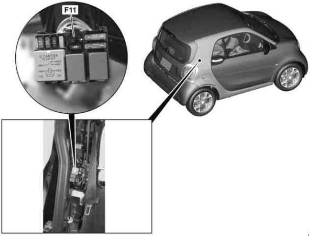
Smart Fortwo (A453, C453, W453; 2014 – present) – fuse box diagram
Year of production: 2014, 2015, 2016, 2017, 2018
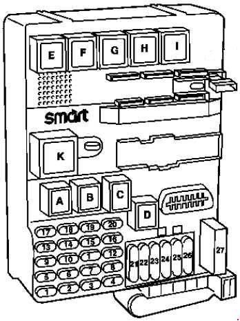
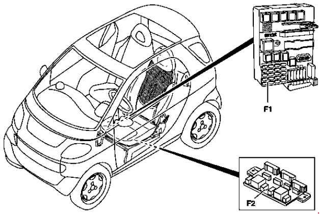
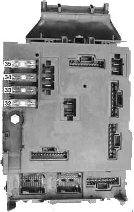
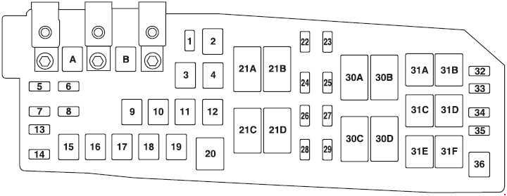
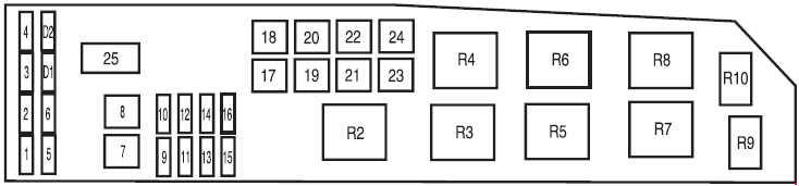
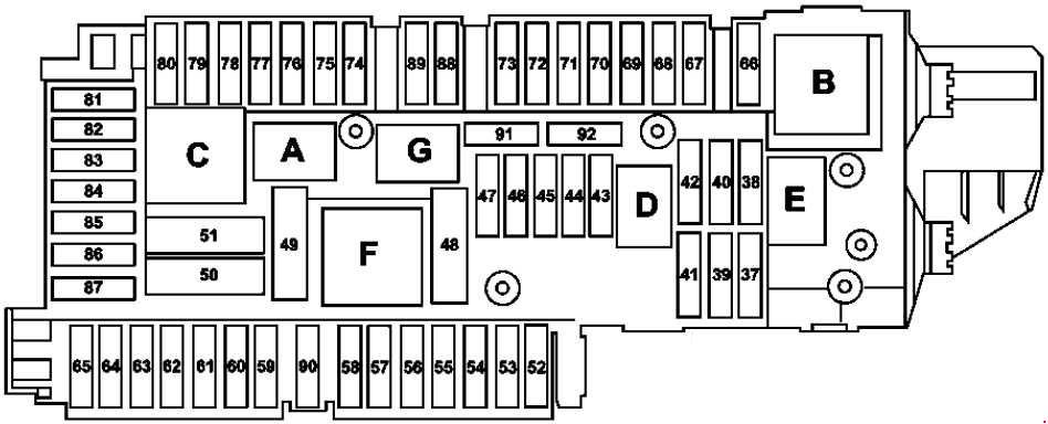
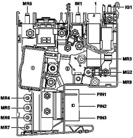
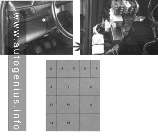
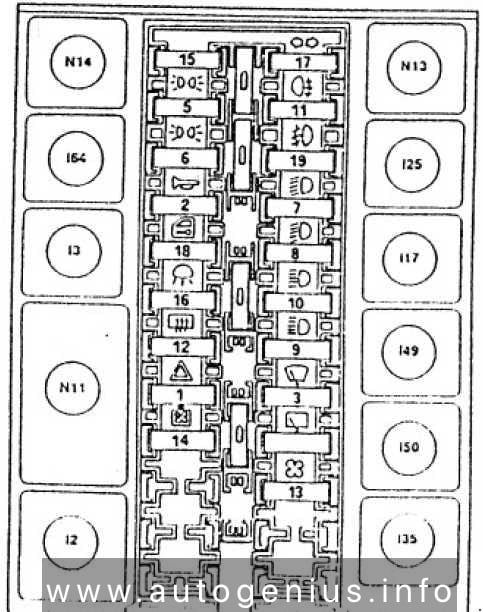
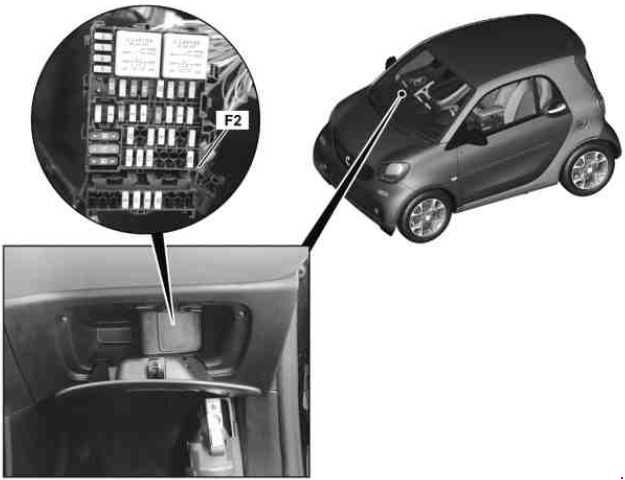
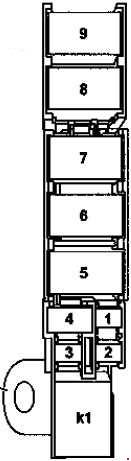
Vehicle interior fuse and relay module
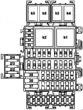
| No. | Fused function | A |
| 1 | Rear roof rack electrical connection | 20 |
| 2 | Spare | — |
| 3 | Spare | — |
| 4 | Spare | — |
| 5 | Driver-side SAM control unit | 25 |
| 6 | Driver-side SAM control unit | 25 |
| 7 | Driver-side SAM control unit | 25 |
| 8 | Center SAM control unit Radio Radio over connector sleeve for terminal 15 R |
15 |
| 9 | Spare | — |
| 10 | Horn | 15 |
| 11 | Battery sensor and driver-side SAM control unit | 5 |
| 12 | Front cigarette lighter with ashtray illumination | 15 |
| 13 | Spare | — |
| 14 | Automatic transmission protected through connector sleeve for circuit 30 Diagnostic connector Valid for electric vehicle: Fused circuit 30 connector sleeve Diagnostic connector |
20 |
| 15 | Supply for fused circuit 30 connector sleeve | 15 |
| 16 | Motor electronics protected through connector sleeve for circuit 30 Valid for electric vehicle: Supply for fused circuit 30 connector sleeve |
5 |
| 17 | Supply protected through connector sleeve for circuit 30 | 15 |
| 18 | Brake lights switch | 10 |
| 19 | Outside mirror adjustment switch | 5 |
| 20 | Transponder coil Electronic Stability Program control unit and brake light switch Protected through connector sleeve for circuit 30 |
3 |
| 21 | Light functions protected through connector sleeve for circuit 30 | 10 |
| 22 | Steering wheel angle sensor Dual-clutch transmission control unit |
5 |
| 23 | Spare | — |
| 24 | Center SAM control unit | 15 |
| 25 | Center SAM control unit | 10 |
| 26 | Center SAM control unit | 15 |
| 27 | Center SAM control unit | 20 |
| 28 | Driver-side SAM control unit | 10 |
| 29 | Driver-side SAM control unit | 10 |
| 30 | Combination switch Alarm siren Supply for fused circuit 30 connector sleeve (valid for electric vehicle) |
15 |
| 31 | Instrument cluster and additional instruments | 10 |
| 32 | Spare | — |
| 33 | Supplemental Restraint System control unit | 5 |
| 34 | Combination switch | 5 |
| 35 | Electrical power steering control unit | 5 |
| 36 | Center SAM control unit | 5 |
| 37 | Driver-side SAM control unit | 30 |
| 38 | Air conditioning power supply solenoid switch | 40 |
| 39 | Starter Through starter relay |
30 |
| Valid for electric vehicle: Blower motor | 40 | |
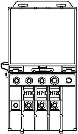
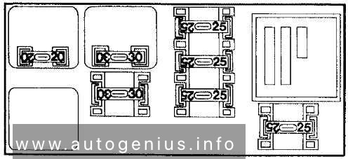
| 1/1 | Valid for electric vehicle: Electric vehicle circuit 30 connector sleeve supply | 10 |
| 1/2 | Valid for electric vehicle: Brake booster vacuum pump control unit Power electronics control unit |
— |
| 1/3 | Spare | — |
| 1/4 | Sound system amplifier control unit | 20 |
| 1/5 | Dual clutch transmission control unit Valid for electric vehicle: Electric drive control unit |
5 |
| 1/6 | Left front power window motor and right front power window motor | 25 |
| 1/7 | Left electrically adjustable and heated outside mirror and right electrically adjustable and heated outside mirror | 5 |
| 1/8 | Valid for electric vehicle: Front passenger seat heater control unit Driver seat heater control unit |
25 |
| 1/9 | Spare | — |
| 1/10 | Valid for electric vehicle: Steering wheel heater relay | — |
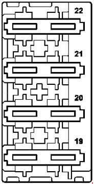
| 2/1 | Supply for soft top control drive unit | 20 |
| 2/2 | Supply for soft top control drive unit | 20 |
| 2/3 | Spare | — |
| 2/4 | Spare | — |
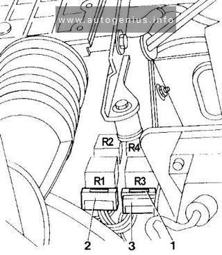
| Relay | ||
| K1 | Heated rear window/outside mirrors relay | |
| K2 | Front power window relay | |
| K3 | Sliding roof relay | |
| K4 | Front headlamps relay | |
| K5 | Starter relay | |
| K6 | Fanfare horn relay | |
| K | Valid for electric vehicle: Steering wheel heater relay | |
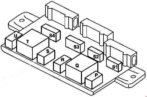
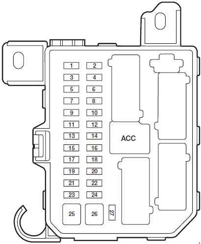
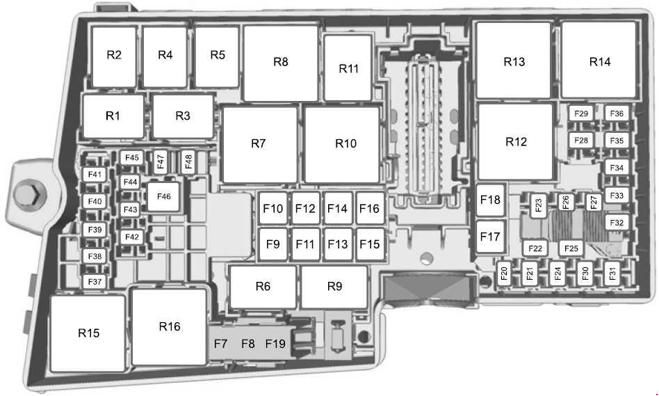
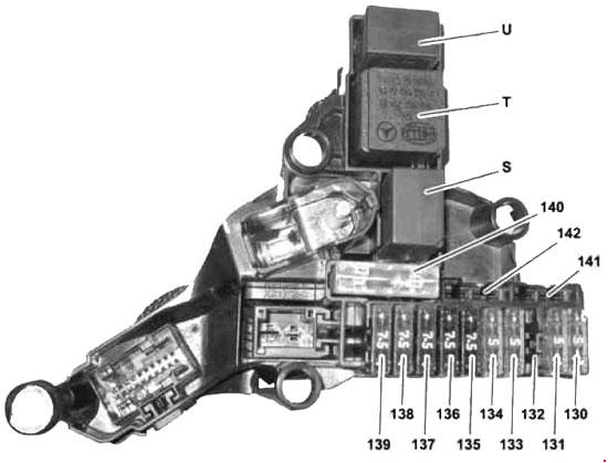
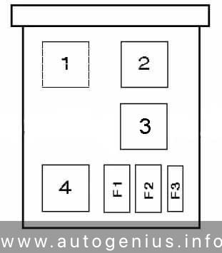
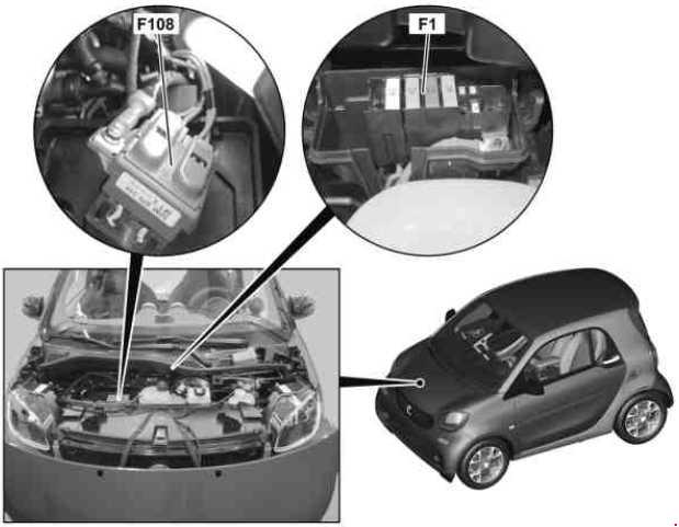
Combustion engine fuse and relay module (F1)
| No. | Fused function | A |
| 1 | Internal combustion engine relay module Valid for electric vehicle: Spare |
Diode |
| 2 | Valid for USA: Supply for vacuum pump relay | Diode |
| Valid for electric vehicle: Transmission mode recognition sensor Electric drive control unit |
15 | |
| 3 | Fuel pump with fill level sensor and temperature sensor | 20 |
| Valid for electric vehicle: Electric vehicle drive motor fan relay | 40 | |
| 4 | Supply for fused circuit 30 connector sleeve | 25 |
| Valid for electric vehicle: Battery cooling system coolant pumps relay | 30 | |
| 5 | Supply for connector sleeves for circuit 87 | 15 |
| Valid for electric vehicle: Battery cooling system coolant pump | 15 | |
| 6 | Refrigerant compressor relay | 15 |
| Valid for electric vehicle: Battery management system control unit Electric drive control unit |
5 | |
| 7 | Fan Through fan relay |
10 |
| Valid for electric vehicle: Power electronics control unit power supply connector sleeve supply | 20 | |
| 8 | Dual clutch transmission control unit | 10 |
| Valid for electric vehicle: Circuit 87 supply connector sleeve | 15 | |
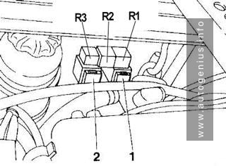
| Relay |
||
| K1 | Engine function circuit 87 relay |
|
| K2 | Fan relay | |
| K3 | Ignition coils/fuel pump actuation relay | |
| K4 | Valid for electric vehicle: Battery cooling system coolant pumps relay | |
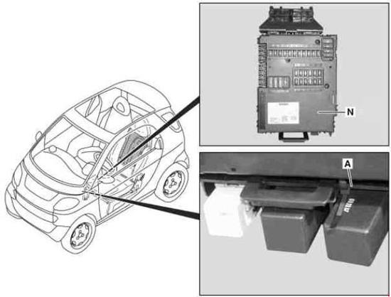
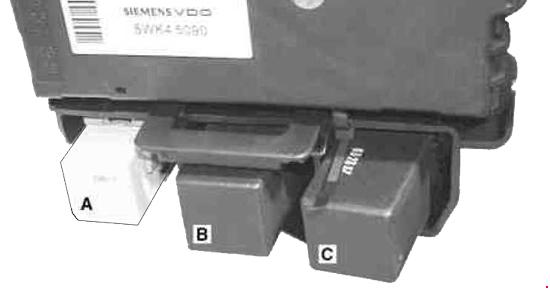
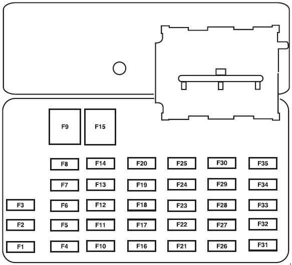
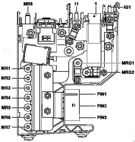
Battery clamp fuse (F108)
| No. | Fused function | A |
| F1 | Electrical fuse 3A (F108f3A) and electrical fuse 3B (F108f3B) Valid for electric vehicle: Power supply fuse and relay module (F1) DC/DC converter control unit |
200 |
| F2A | Vehicle interior fuse and relay module supply (F2) Protected through connector sleeve for circuit 30 Connector sleeve for circuit 30 |
70 |
| F2B | Electrical power steering control unit | 60 |
| F3A | Vehicle interior fuse and relay module supply (F2) Ignition lock Protected through connector sleeve for circuit 30 Connector sleeve for circuit 30 |
70 |
| F3B | Electronic Stability Program control unit | 50 |
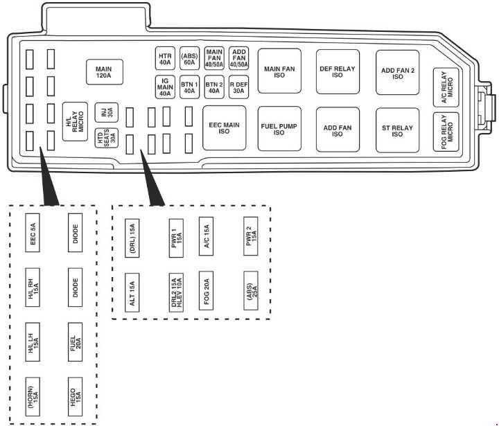
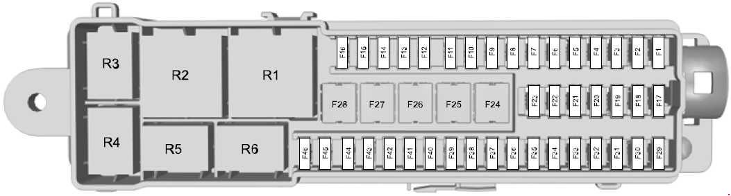
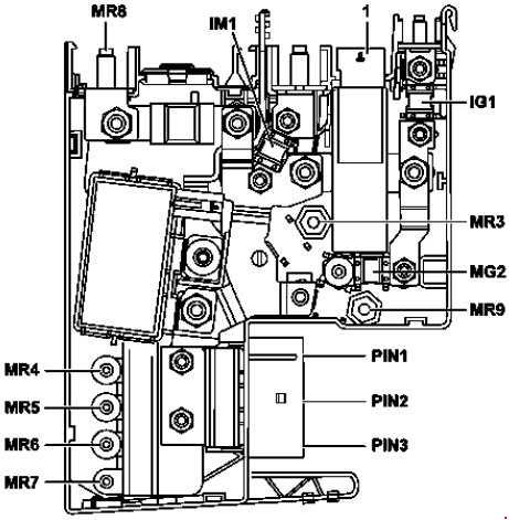
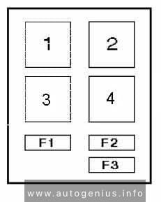
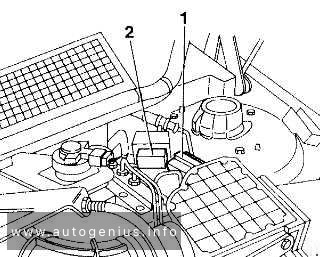
Power supply fuse and relay module
| No. | Fused function | A |
| 1 | Heated rear window over relay for heated rear window/outside mirrors | 30 |
| 2 | Front passenger seat heater control unit Driver seat heater control unit Valid for electric vehicle: Brake booster vacuum pump control unit |
30 |
| 3 | Supply for Electronic Stability Program control unit | 25 |
| 4 | Valid for electric vehicle: Spare Electrical fuse 1 and electrical fuse 2 |
40 |
| Sliding roof relay | 25 | |
| 5 | Supply for internal combustion engine fuse and relay module | 60 |
| 6 | Dual clutch transmission control unit Protected through connector sleeve for circuit 30 |
50 |
| Valid for electric vehicle: Vehicle interior fuse and relay module supply | 40 | |
| 7 | Fan motor Over fan relay |
30 |
| Fan solenoid switch ICE combustion engine cooling |
30 | |
| 8 | Spare | — |
| 9 | Valid for USA:Secondary air injection pump Valid for electric vehicle: Heater for high-voltage battery Over heater relay for high-voltage battery |
60 |
| Relay |
||
| K1 | Fan relay |
|
WARNING: Terminal and harness assignments for individual connectors will vary depending on vehicle equipment level, model, and market.