BYD Dolphin (2021 – 2023) – fuse and relay box diagram
Year of production: 2021, 2022, 2023
This article provides fuse box diagrams for the BYD Dolphin models from 2021, 2022, and 2023. It also includes details on the location of the fuse panels within the car and an overview of the fuse assignments (fuse layout).
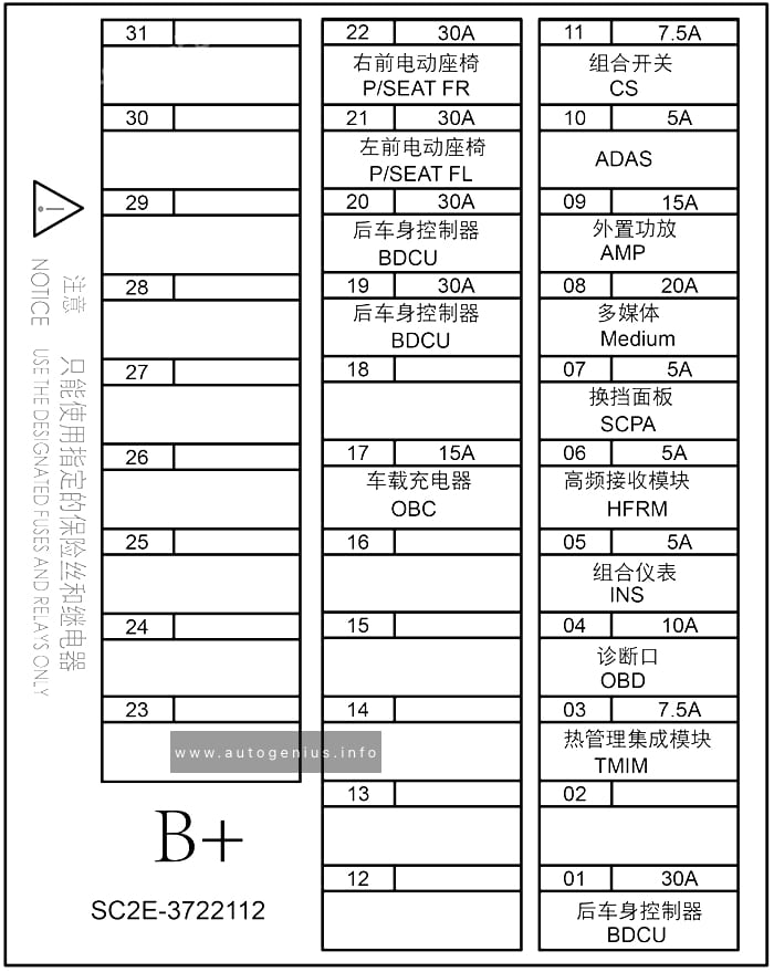
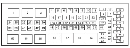
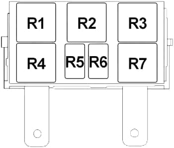
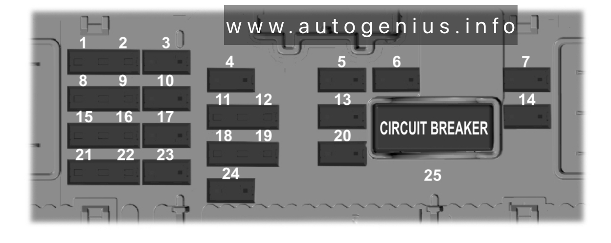
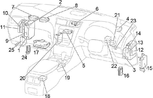
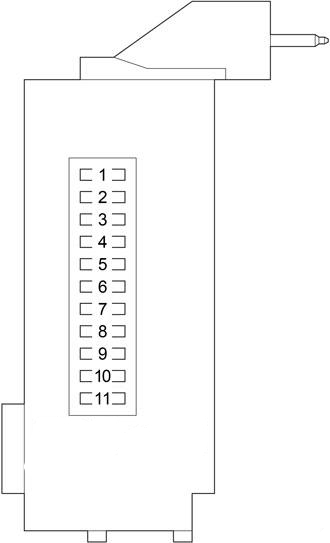
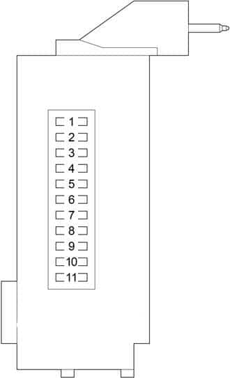
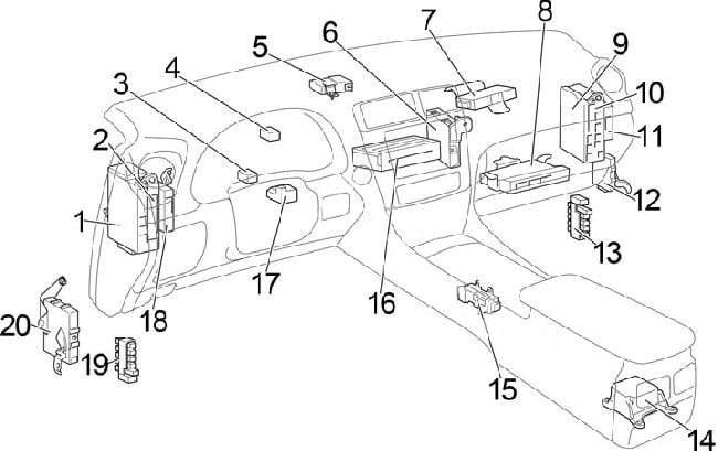
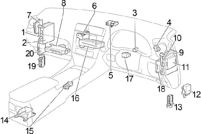
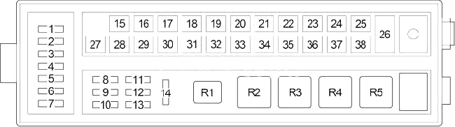
Instrument panel fuse box
Fuse Box Location
The dashboard panel fuses are located under the driver side of the dashboard.

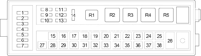
Fuse Box Diagram
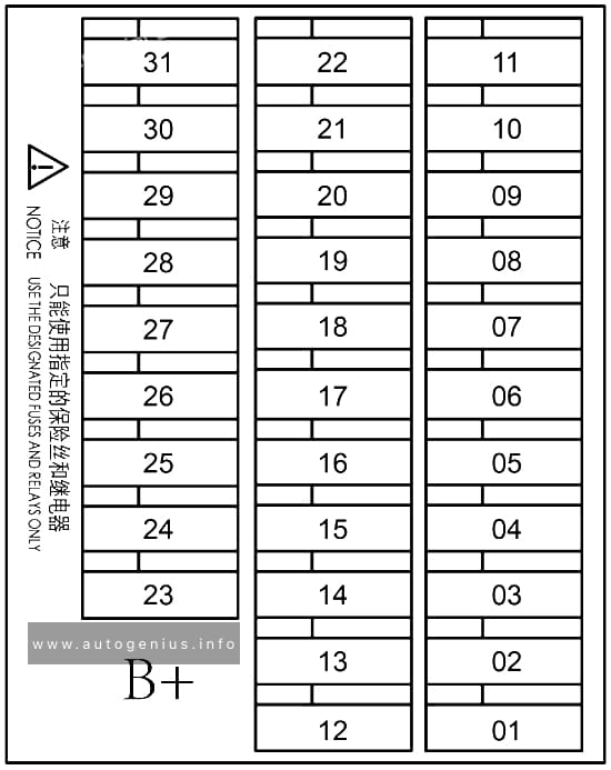
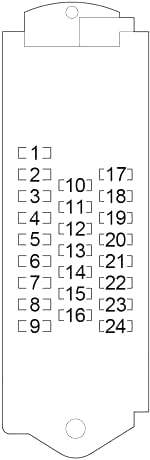
Assignment of the fuses in the instrument panel
| № | Amps | Protected Component or Circuit |
|---|---|---|
| 01 | 30A | Universal controller |
| 02 | 30A | Towing power supply |
| 03 | 5A | Brake light switch |
| 04 | 10A | Diagnosis port |
| 05 | 5A | Instrument cluster |
| 06 | 10A | Alcohol interlock |
| 07 | 5A | Gearshift panel |
| 08 | 20A | Infotainment system |
| 09 | 15A | External amplifier |
| 10 | 10A | ADAS |
| 11 | 7.5A | Combination switch |
| 12 | 30A | Rear body control module |
| 13 | 30A | Rear body control module |
| 14 | 10A | CCS |
| 15 | 20A | Left front window |
| 16 | 20A | Right front window |
| 17 | 20A | Left rear window |
| 18 | 20A | Right rear window |
| 19 | 5A | E-Call |
| 20 | 7.5A | Wireless charger |
| 21 | 30A | Left front power seat |
| 22 | 30A | Right front power seat |
| 23 | – | – |
| 24 | – | – |
| 25 | – | – |
| 26 | – | – |
| 27 | – | – |
| 28 | – | – |
| 29 | – | – |
| 30 | – | – |
| 31 | – | – |
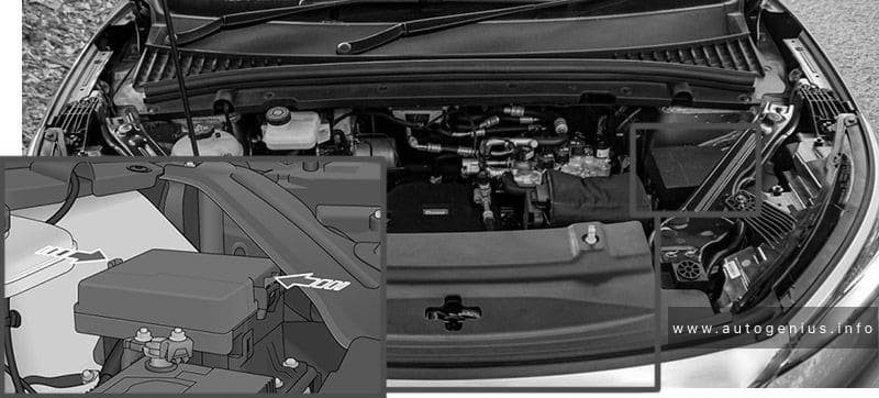
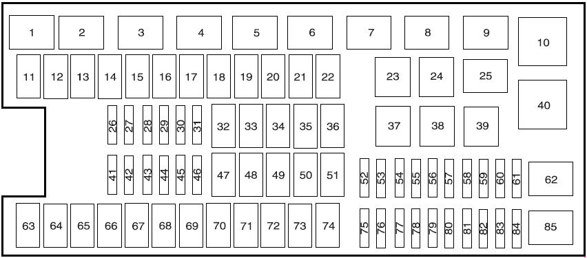
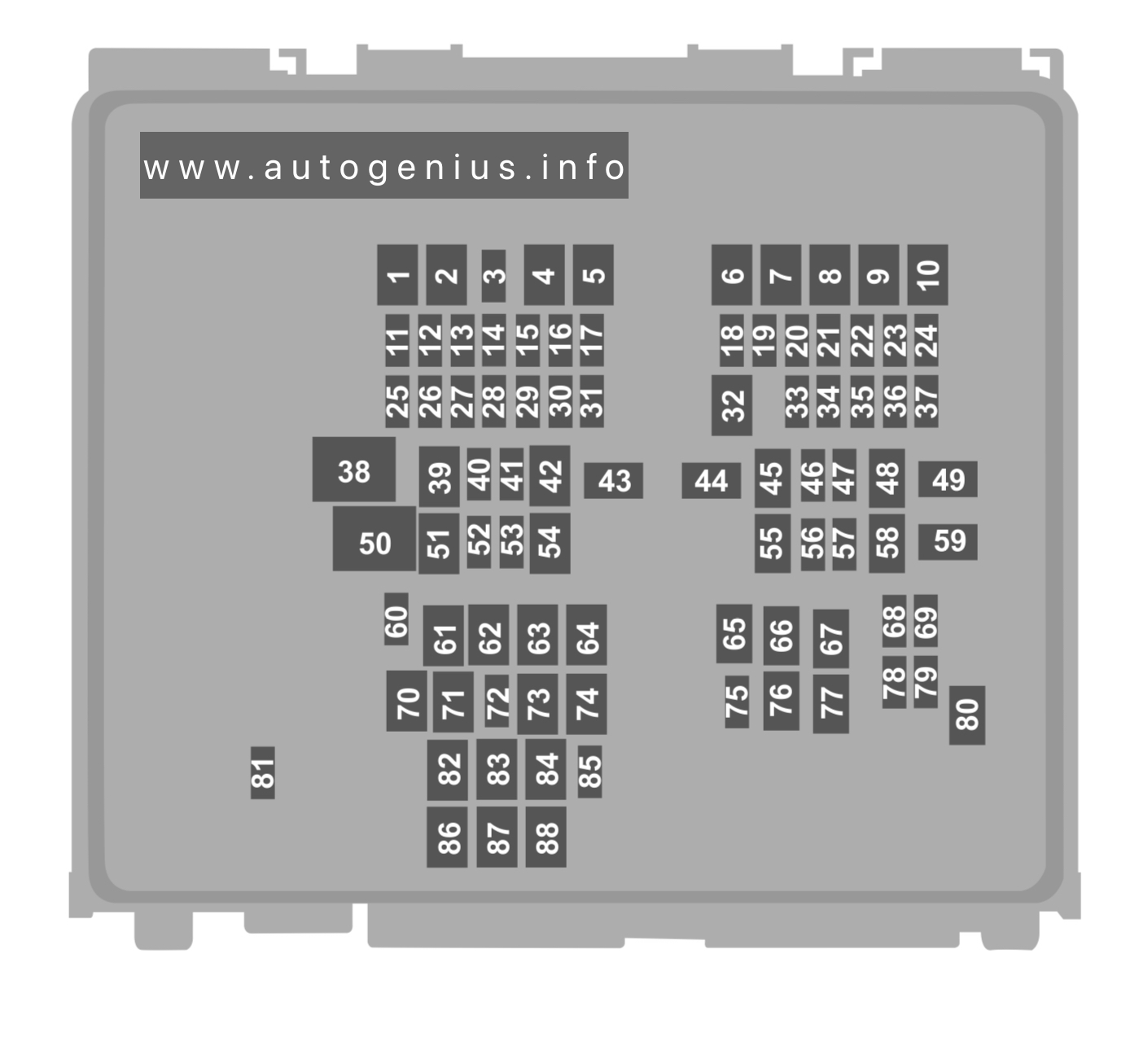
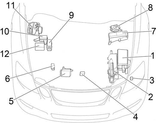
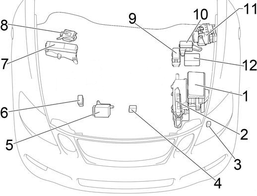
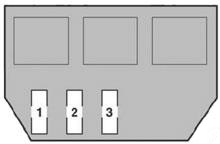
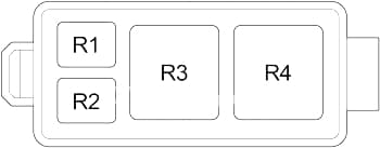
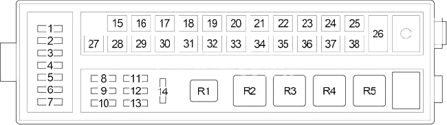
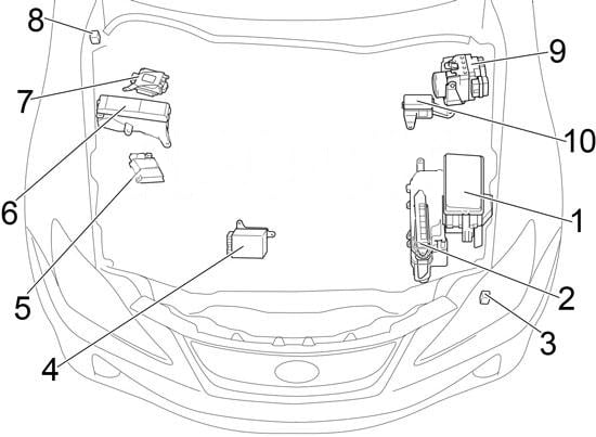
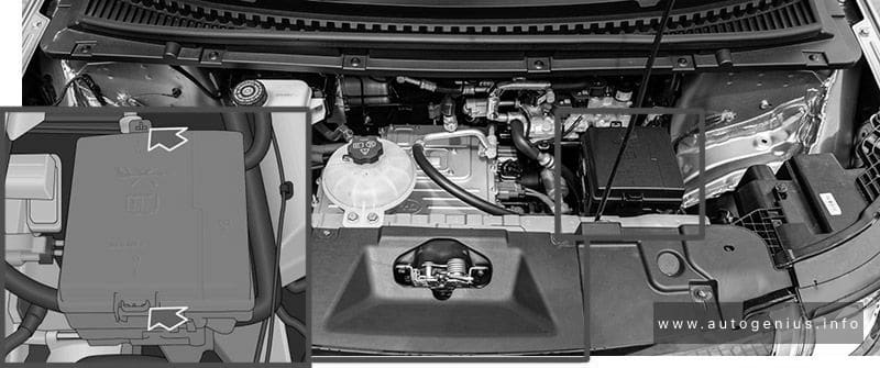
Engine Compartment Fuse Box
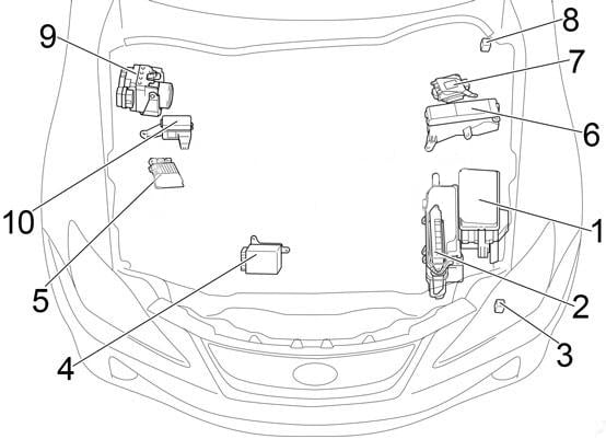
Fuse Box Location
The fuse under the hood is located on the rear left side of the motor compartment.
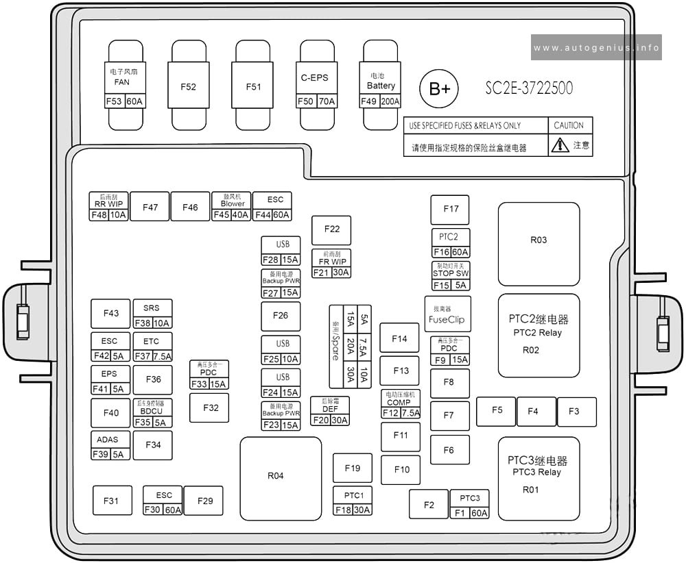
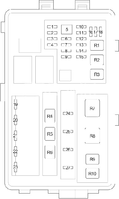
Fuse Box Diagram
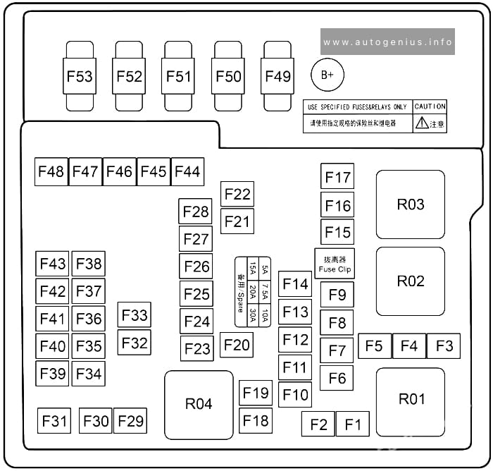
Assignment of the fuses in the engine compartment
| № | Amps | Protected Component or Circuit |
|---|---|---|
| F1 | 60A | PTC3 |
| F2 | – | – |
| F3 | – | – |
| F4 | – | – |
| F5 | – | – |
| F6 | – | – |
| F7 | – | – |
| F8 | – | – |
| F9 | 15A | HV all-in-one controller |
| F10 | 15A | Left combination headlight |
| F11 | 15A | Right combination headlight |
| F12 | 7.5A | Compressor |
| F13 | 10A | Electrically controlled cooling water pump |
| F14 | 10A | Motor controller |
| F15 | 7.5A | Integrated thermal management module |
| F16 | 60A | PTC2 |
| F17 | – | – |
| F18 | 30A | PTC1 |
| F19 | – | – |
| F20 | 7.5A | Right daytime running light |
| F21 | 30A | Front wiper |
| F22 | 30A | Rear defroster |
| F23 | 15A | Auxiliary power |
| F24 | 15A | USB |
| F25 | 10A | USB |
| F26 | – | – |
| F27 | 15A | Auxiliary power |
| F28 | 15A | USB |
| F29 | – | – |
| F30 | 60A | ESC |
| F31 | 20A | Towing power supply |
| F32 | – | – |
| F33 | 15A | HV all-in-one controller |
| F34 | 15A | Steering wheel heater |
| F35 | 5A | Rear body control module |
| F36 | 5A | Instrument cluster |
| F37 | 7.5A | ETC |
| F38 | 10A | SRS |
| F39 | 5A | ADAS |
| F40 | – | – |
| F41 | 5A | EPS |
| F42 | 5A | ESC |
| F43 | – | – |
| F44 | 60A | ESC |
| F45 | 40A | Blower |
| F46 | – | – |
| F47 | – | – |
| F48 | 10A | Rear wiper |
| F49 | 200A | Battery |
| F50 | 70A | CEPS |
| F51 | – | – |
| F52 | 60A | Electric fan |
| F53 | – | – |
WARNING: Terminal and harness assignments for individual connectors will vary depending on vehicle equipment level, model, and market.