Lincoln MKX (2006 – 2010) – fuse box diagram
Year of production: 2006, 2007, 2008, 2009, 2010
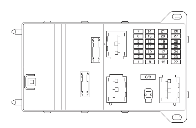
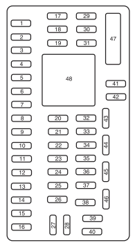
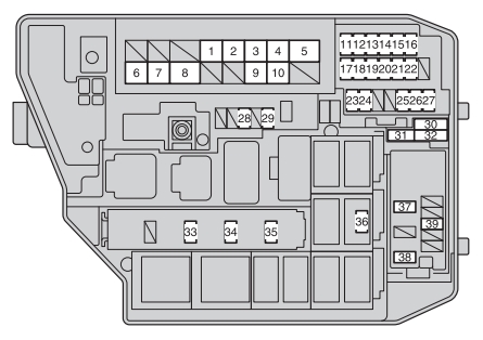
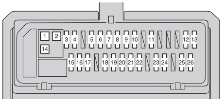
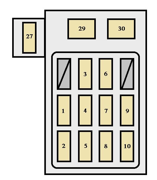
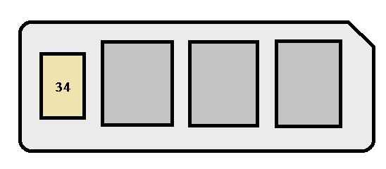
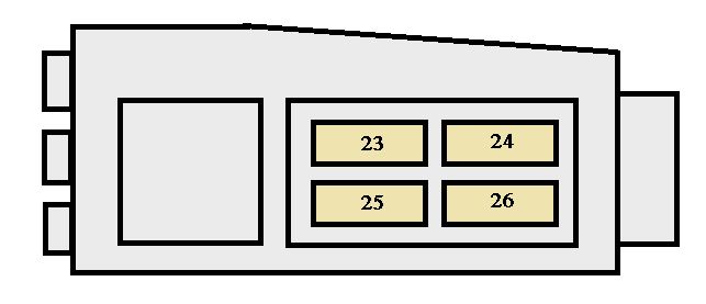
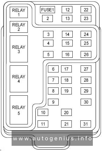
Passenger compartment fuse panel
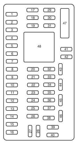
| No. | A | Protected components |
| 1 | 30 | ’07: Driver front smart window ’08-’10: Passenger front smart window |
| 2 | 15 | ’10: High-mount brake lamp (brake on/off) |
| 3 | 15 | Family entertainment system (FES)/Rear seat control (’07-’08), SYNC (’08-’10) |
| 4 | 30 | ’07: Passenger front smart window ’08-’10: Driver front smart window |
| 5 | 10 | Keypad illumination, 2nd row seat, Tire Pressure Monitoring System (TPMS (’07-’09)), Brake Shift Interlock (BSI (’07-’09)), Smart junction box (SJB (’09)) |
| 6 | 20 | Turn signals |
| 7 | 10 | Low beam headlamps (left) |
| 8 | 10 | Low beam headlamps (right) |
| 9 | 15 | Interior lights, Cargo lamps |
| 10 | 15 | Backlighting, Puddle lamps, Ambient lighting (’09) |
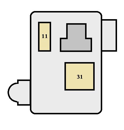
| 11 | 10 | All wheel drive |
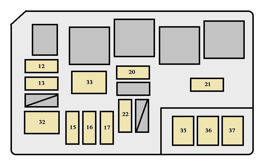
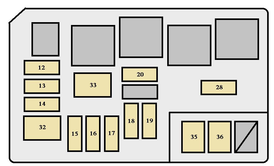
| 12 | 7.5 | Power mirror switch, Driver side power seat memory, Driver seat module – Keep alive power (KA) |
| 13 | 7.5 | Satellite radio (’09-’10), DSP (’09) |
| 14 | 10 | Power liftgate module |
| 15 | 10 | Climate control, GPS module (’10) |
| 16 | 15 | Not used (Spare) |
| 17 | 20 | All power lock motor feeds, Liftgate release, Moon roof (’07-’08), Express up/down front windows (’09-’10) |
| 18 | 20 | THX system, Heated seats (’09) |
| 19 | 25 | Rear wiper |
| 20 | 15 | Datalink |
| 21 | 15 | Fog lamps |
| 22 | 15 | Park lamps |
| 23 | 15 | High beam headlamps |
| 24 | 20 | Horn relay |
| 25 | 10 | Demand lamps/interior lamps |
| 26 | 10 | Instrument panel cluster |
| 27 | 20 | Ignition switch |
| 28 | 5 | Radio |
| 29 | 5 | Instrument panel cluster |
| 30 | 5 | Overdrive cancel switch |
| 31 | 10 | Compass (’07), Automatic dimming rear view mirror (’07-’09) |
| 32 | 10 | ’10: Restraint control module |
| 33 | 10 | Not used (Spare) |
| 34 | 5 | Steering angle sensor |
| 35 | 10 | Rear park assist, All wheel drive (AWD (’07-’09)), Heated seat module, Yaw rate sensor (’10) |
| 36 | 5 | Passive anti-theft system (PATS) transceiver |
| 37 | 10 | Climate control |
| 38 | 20 | ’07-’09: THX System ’10: Subwoofer/amplifier |
| 39 | 20 | Radio |
| 40 | 20 | Not used (Spare) |
| 41 | 15 | Delayed accessory function for radio and lock switch illumination (’07-’09), Ambient lighting (’09), Automatic dimming rear view mirror (’10) |
| 42 | 10 | Not used (Spare) |
| 43 | 10 | Rear wiper logic |
| 44 | 10 | Customer accessory feed |
| 45 | 5 | Front wiper logic, Climate control relay feed (’07-’09) |
| 46 | 7.5 | Occupant Classification Sensor (OCS), Passenger Airbag Deactivation Indicator (PADI) |
| 47 | 30 | Circuit Breaker: Power windows |
| Relay | ||
| 48 | Delayed accessory | |
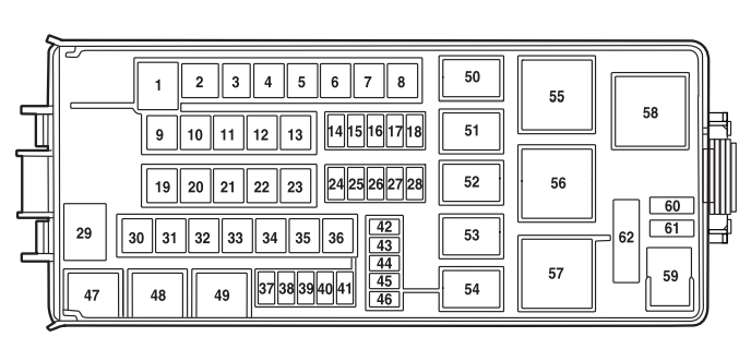
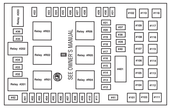
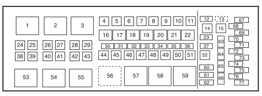
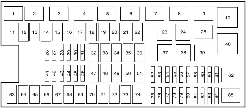
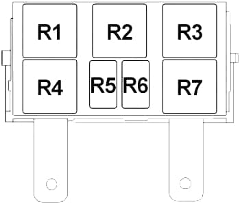
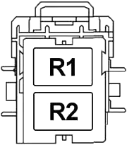
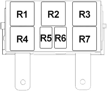
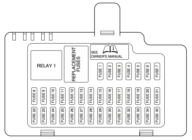
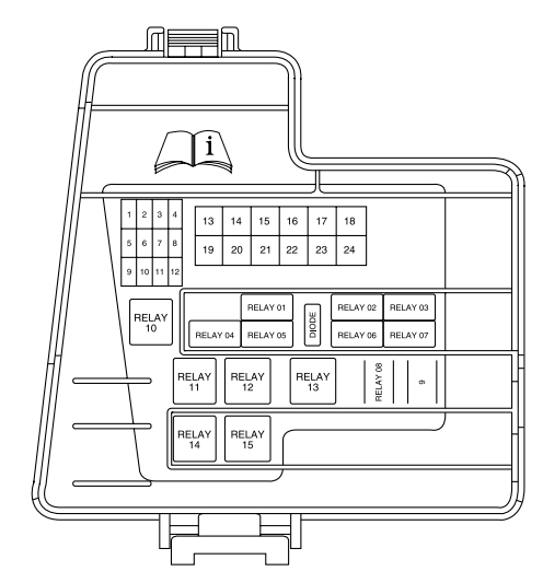
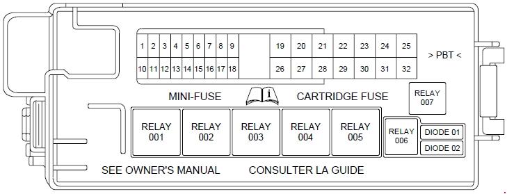
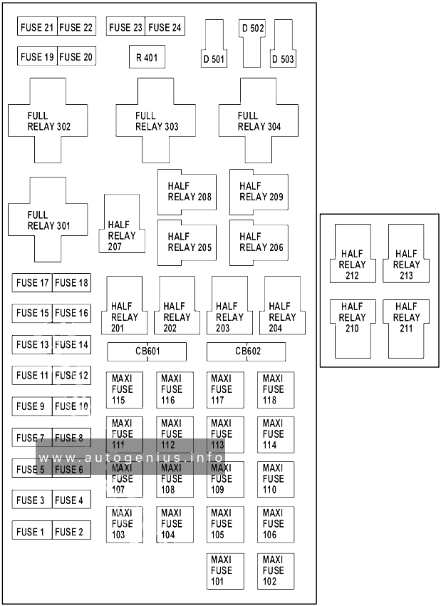
Engine Compartment Fuse Box
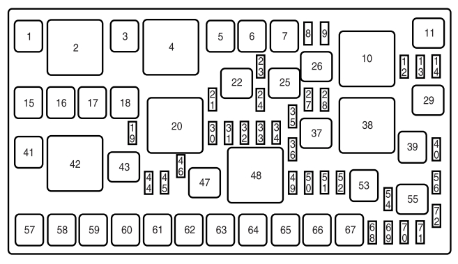
| No. | A | Protected components |
| 1 | — | Not used |
| 3 | — | Not used |
| 5 | 40 | Cooling fan (vehicles with trailer tow) |
| 60 | Cooling fan (vehicles without trailer tow) | |
| 6 | 40 | Cooling fan (trailer tow only) |
| 7 | 30 | Rear heated seats |
| 8 | 10 | Alternator |
| 9 | 20 | Trailer tow parking lamps |
| 12 | — | Not used |
| 13 | — | Not used |
| 14 | — | Not used |
| 15 | 40 | ABS pump motor |
| 16 | 30 | Front heated seats |
| 17 | 20 | Cigar lighter/Power point |
| 18 | 30 | ’07: Panorama moon roof |
| 20 | ’08-’10: Panorama moon roof | |
| 21 | 7.5 | Powertrain control module (PCM) – Keep alive power (KA) |
| 24 | 15 | ’07: Trailer tow left stop/turn lamp |
| 10 | ’08-’10: Trailer tow left stop/turn lamp | |
| 27 | 10 | Rear seat release |
| 28 | 15 | Heated mirror |
| 30 | 15 | VPWR 1 – PCM |
| 31 | 10 | VPWR 3 – PCM |
| 32 | 10 | VPWR 2 – PCM |
| 33 | 15 | VPWR 4 – PCM |
| 34 | — | Not used |
| 35 | 10 | A/C clutch |
| 36 | — | Not used |
| 39 | 40 | Rear window defroster |
| 40 | — | Not used |
| 41 | 30 | Starter |
| 44 | 10 | Backup lamps |
| 45 | — | Not used |
| 46 | 15 | ’07: Trailer tow right stop/turn lamp |
| 10 | ’08-’10: Trailer tow right stop/turn lamp | |
| 49 | 10 | PCM ISPR |
| 50 | 10 | ABS Run/Start |
| 51 | 5 | Adaptive lighting |
| 52 | 5 | Fuel pump relay coil |
| 53 | 30 | Passenger compartment fuse panel run/start |
| 54 | — | Not used |
| 55 | — | Not used |
| 57 | 40 | Anti-lock brake system valves |
| 58 | 30 | Front wipers |
| 59 | 30 | Power liftgate |
| 60 | 30 | Driver power seat |
| 61 | 30 | Passenger power seat |
| 62 | — | Not used |
| 63 | 40 | Blower motor |
| 64 | 20 | Cigar lighter/Power point |
| 65 | 20 | Cigar lighter/Power point |
| 66 | 20 | Cigar lighter/Power point |
| 67 | — | Not used |
| 68 | 15 | Fuel pump |
| 69 | — | Not used |
| 70 | — | Not used |
| 71 | 10 | Stop lamps (Brake on/off switch) |
| 72 | — | Not used |
| Diode | ||
| 19 | Fuel pump | |
| 23 | ’09-’10: One-touch integrated start | |
| 56 | A/C clutch | |
| Relay | ||
| 2 | Blower motor | |
| 4 | Not used | |
| 10 | Not used | |
| 11 | Trailer tow parking lamp | |
| 20 | PCM | |
| 22 | Trailer tow left stop/turn lamp | |
| 25 | Rear seat release | |
| 26 | Fuel pump | |
| 29 | Heated mirror | |
| 37 | A/C clutch | |
| 38 | Rear window defroster | |
| 42 | Starter | |
| 43 | Backup lamp | |
| 47 | Trailer tow right stop/turn lamp | |
| 48 | Run/Start | |
WARNING: Terminal and harness assignments for individual connectors will vary depending on vehicle equipment level, model, and market.