Lincoln Blackwood (2001) – fuse box diagram
Year of production: 2001
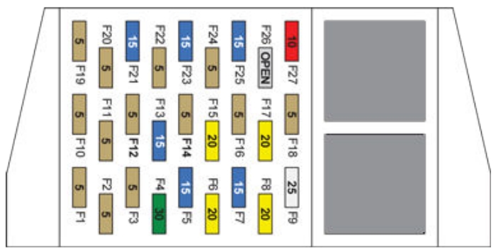
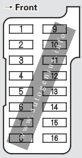
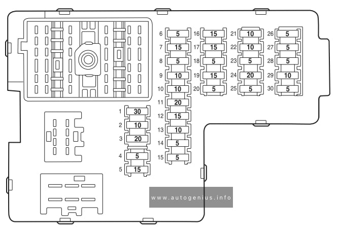
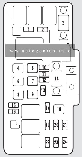
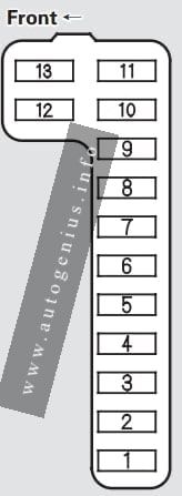
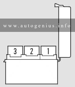
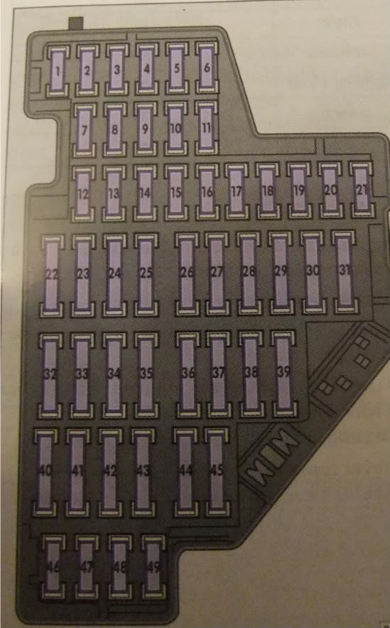
Passenger compartment fuse panel
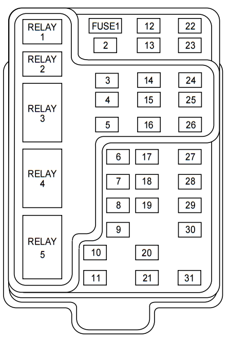
| Fuse/relay | Ampere rating [A] | Description |
| 1 | 25 | Radio, Amplifier, I/P fuse 31 |
| 2 | 5 | Powertrain Control Module (PCM), Instrument Cluster, Electronic Automatic Temperature Control (EATC), Overhead Trip Computer Module (OTC), Navigation Module, Clock |
| 3 | 20 | Cigar Lighter, Data Link Connector |
| 4 | 7,5 | Mirrors, Seats, Pedals, (memory) |
| 5 | 15 | Speed Control Module, Reverse Lamp, Reverse Sensing System (RSS), E/C Mirror, Central Security Module, Navigation Module |
| 6 | 5 | Cluster, Brake Shift Interlock Solenoid, Generic Electronic Module (GEM), RSS, Air Suspension, OTC, Compass, Automatic Parking Brake Release |
| 7 | 5 | Console Blower Relay |
| 8 | 5 | E/C mirror, Navigation Module, Clock, GEM |
| 9 | — | Not Used |
| 10 | — | Not Used |
| 11 | 30 | Front Washer Pump Relay, Wiper Run/Park Relay, Wiper Hi/LO Relay, Windshield Wiper Motor |
| 12 | 15 | Air Suspension |
| 13 | 20 | Stop Lamp Switch (Lamps), Turn/Hazard Flasher, Trailer Brake, Radio Frequency Interference Module (RFI) |
| 14 | 15 | Battery Saver Relay, Interior Lamp Relay, Accessory Delay Relay (Power Windows) |
| 15 | 5 | Stop Lamp Switch, (Speed Control, Brake Shift Interlock, Anti-lock Brake System (ABS), PCM Module Inputs, Traction Control, Air Suspension, Central Security Module, GEM Module |
| 16 | 20 | Headlamps (Hi Beams), Cluster (Hi Beam Indicator) |
| 17 | 10 | Heated Mirrors, Rear Defrost |
| 18 | 5 | Instrument Illumination (Dimmer Switch Power) |
| 19 | — | Not used |
| 20 | 5 | GEM, Power Tonneau Cover, Air Suspension, Memory |
| 21 | 15 | Starter Relay, Fuse 20 of the Fuse Panel , Radio |
| 22 | 10 | Air Bag Module |
| 23 | 10 | Trailer Tow Battery Charge Relay, Turn/Hazard Flasher, Rear Console Controls, Climate Control Seats, Traction Control Module |
| 24 | 10 | I/P Fuse 7, EATC, Blower Relay |
| 25 | — | Not used |
| 26 | 10 | Right Side Low Beam Headlamp |
| 27 | 5 | Fog lamp Relay and Fog lamp Indicator |
| 28 | 10 | Left Side Low Beam Headlamp |
| 29 | 5 | Autolamp Module, Transmission Overdrive Control Switch, Central Security Module, Power Tonneau |
| 30 | 30 | Passive Anti Theft Transceiver, Instrument Cluster, Ignition Coils, Powertrain Control Module Relay |
| 31 | 10 | CD Changer, Rear Console Controls |
| Relay 1 | — | Interior Lamp Relay |
| Relay 2 | — | Battery Saver Relay |
| Relay 3 | — | Heated Grid Relay |
| Relay 4 | — | One Touch Down Window Relay |
| Relay 5 | — | Ignition Key Accessory Delay Relay |
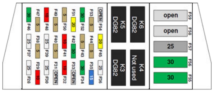
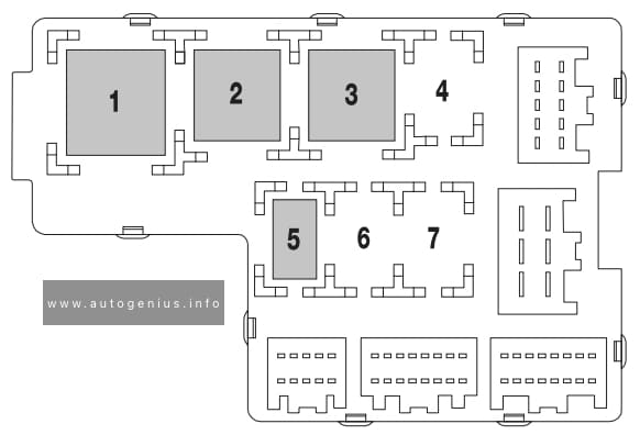
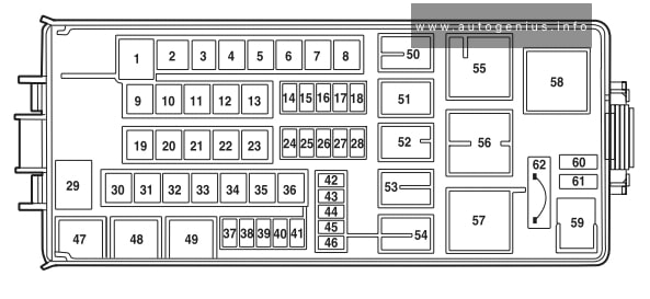
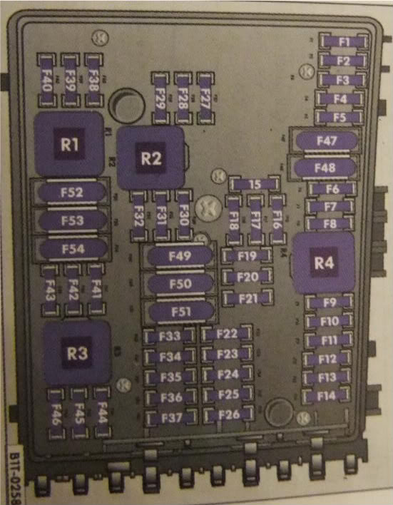
Power distribution box
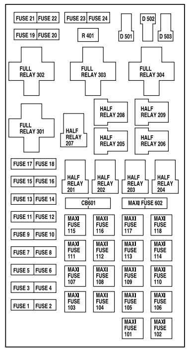
| Fuse/relay | Ampere rating [A] | Description |
| 1 | 20* | Power Point |
| 2 | 30* | Powertrain Control Module |
| 3 | 30* | Headlamps/Autolamps |
| 4 | 20* | Console Power Point |
| 5 | 20* | Trailer Tow Backup/Park Lamps |
| 6 | 15* | Parklamps/Autolamps, Passenger Fuse Panel Feed Fuse #18 |
| 7 | 20* | Horn |
| 8 | 30* | Power Door Locks |
| 9 | 15* | Fog Lamps, Power Tonneau |
| 10 | 20* | Fuel Pump |
| 11 | 20* | Alternator Field |
| 12 | 20* | Rear Auxiliary Power Point |
| 13 | 15* | A/C Clutch |
| 14 | 20* | Box Power Point |
| 15 | — | Not Used |
| 16 | — | Not Used |
| 17 | 10* | Delayed ACC |
| 18 | 15* | Powertrain Control Module, Fuel Injectors, Fuel Pump Relay, Idle Air Control, Mass Air Flow Sensor |
| 19 | 10* | Trailer Tow Stop and Right Turn Lamp |
| 20 | 10* | Trailer Tow Stop and Left Turn Lamp |
| 21 | — | Not Used |
| 22 | — | Not Used |
| 23 | 15* | HEGO Sensor, Canister Vent, Automatic Transmission, CMS Sensor |
| 24 | — | Not Used |
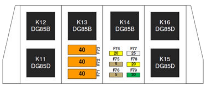
| 101 | 30** | Trailer Tow Battery Charge |
| 102 | 50** | Four Wheel Antilock Brake Module, Traction Control |
| 103 | 50** | Junction Block Battery Feed |
| 104 | — | Not used |
| 105 | 40** | Climate Control Front Blower |
| 106 | — | Not used |
| 107 | 30** | Passenger Power Seat |
| 108 | 30** | Trailer Tow Electric Brake |
| 109 | 50** | Air Suspension |
| 111 | 40** | Ignition Switch Battery Feed (Start and Run Circuits) |
| 112 | 30** | Drivers Power Seat, Adjustable Pedals |
| 113 | 40** | Ignition Switch Battery Feed (Run and Accessory Circuits) |
| 114 | — | Not Used |
| 115 | — | Not Used |
| 116 | 40** | Heated Grid / Mirrors |
| 117 | — | Not Used |
| 118 | — | Not Used |
| 201 | — | Trailer Tow Park Lamp Relay |
| 202 | — | Front Wiper Run/Park Relay |
| 203 | — | Trailer Tow Backup Lamp Relay |
| 204 | — | A/C Clutch Relay |
| 205 | — | Not Used |
| 206 | — | Fog Lamp Relay |
| 207 | — | Front Washer Pump Relay |
| 208 | — | Not Used |
| 209 | — | Not Used |
| 301 | — | Fuel Pump Relay |
| 302 | — | Trailer Tow Battery Charge Relay |
| 303 | — | Wiper High / Low Relay |
| 304 | — | Powertrain Control Module Relay |
| 401 | — | Not Used |
| 501 | — | Powertrain Control Module Diode |
| 502 | — | A/C Compressor Diode |
| 503 | — | Auto Park Brake Diode |
| 601 | 30 CB | Power Windows, Moonroof |
| 602 | 50** | Power Tonneau |
| *Mini fuses
**Maxi fuses |
||
WARNING: Terminal and harness assignments for individual connectors will vary depending on vehicle equipment level, model, and market.