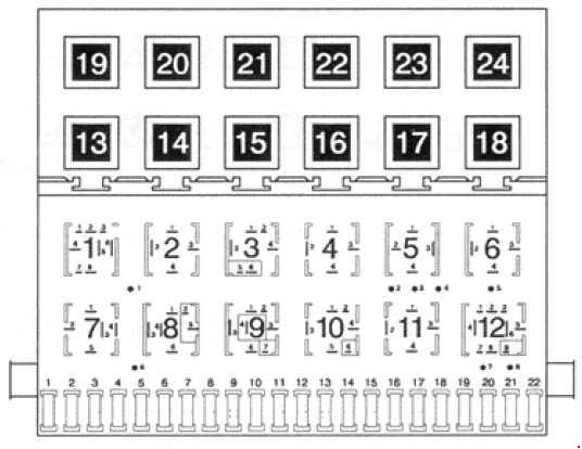
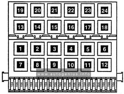
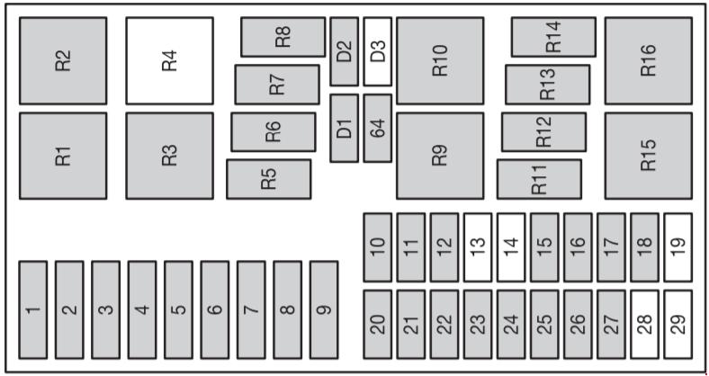
Mercedes-Benz Sprinter (w906) (2006 – 2017) – fuse box diagram

Mercedes-Benz Sprinter (w906) (2006 – 2017) – fuse box diagram

Year of production: 2006, 2007, 2008, 2009, 2010, 2011, 2012, 2013, 2014, 2015, 2016, 2017

Main fuse box

Fuse box in the footwell on the left-hand side of the vehicle.

Mercedes-Benz Sprinter - w906 - fuse box diagram - main fuse box
Mercedes-Benz Sprinter – w906 – fuse box diagram – main fuse box

Consumer A
1 Horn 15
2 ESTL (electric steering lock) ignition lock 25
3 Terminal 30 Z, vehicles with a gasoline engine/ ignition lock/instrument cluster 10
4 Light switch/switch unit on center console 5
5 Windshield wipers 30
6 Fuel pump
Terminal 87 (5)1
15
10
7 MRM (jacket tube module) 5
8 Terminal 87 (2) 20
9 Terminal 87 (1)
Terminal 87 (3), vehicles with a gasoline engine
Terminal 87 (3), vehicles with a diesel engine
25
20
25
10 Terminal 87 (4) 10
11 Terminal 15 R vehicle 15
12 Air bag control unit 10
13 Cigarette lighter/glove box lamp/radio/body manufacturer loading tailgate/PND (personal navigation device) power socket 15
14 Diagnostics connection/light switch/instrument cluster/deactivating reverse warning device/anti-theft protection with vehicle tracking 5
15 Headlamp range con- trol/front-compartment heating 5
16 Terminal 87 (1)
Terminal 87 (3)1
10
17 Air bag control unit 10
18 Terminal 15 vehicle/ brake light switch 7.5
19 Interior lighting 7.5
20 Front-passenger door power window switch/ terminal 30/2 SAM (signal acquisition and actuation module) 25
21 Engine control unit 5
22 Brake system (ABS) 5
23 Starter motor
Terminal 87 (6)1
20
10
24 Diesel engine, engine components/control unit, vehicles with a natural gas engine NGT2 10
25 12 V socket (center console) for tire sealant 25
Fuse block F55/1
1 Driver’s door control unit 25
2 Diagnostics connection 10
3 Brake system (valves) 25
4 Brake system (delivery pump) 40
5 Terminal 87 (2a) engine M272, OM651
Terminal 87 (2a) engine OM642, OM6513
7.5
6 Terminal 87 (1a) engine OM6426
Terminal 87 (1a) engine OM6516
Terminal 87 (3a) engine M272, M271, OM651
10
7.5
7.5
7 Headlamp cleaning system 30
8 Anti-theft alarm system (ATA)/beacon/beacon with siren 15
9 Additional turn signal module 10
Fuse block F55/2
10 Radio 1 DIN
Radio 2 DIN
15
20
11 Mobile phone/tachograph/additional recorder4/navigation cradle6 7.5
12 Front blower/auxiliary heating blower setting 1 30
13 Auxiliary heating system digital timer/radio receiver/DIN slot basic wiring/FleetBoard/antitheft protection with vehicle tracking 7.5
14 Seat heating 30
15 Brake system control unit 5
16 Heating, rear compartment heating/ front-compartment air conditioning 10
17 Convenience lighting
Motion detector
Reading and cargo compartment lamp (courier vehicles)
Cargo compartment lighting
10
7.5
10
7.5
18 Rear-compartment air-conditioning system 7.5
Relays
R1 Horn relay
R2 Windshield wiper setting 1/2 relay
R3
Fuel pump relay5
Starter relay, terminal 151
R4 Windshield wipers on/off relay
R5 Starter relay, terminal 50
R6 Relay, terminal 15 R (normally open contact)
R7 Engine control unit relay, terminal 87
R8 Relay, terminal 15 (reinforced relay)
1 – Vehicles with code MI6/MH3/XM0.
2 – Natural Gas Technology.
3 – NAFTA
4 – Latin America only.
5 – Not on vehicles with code MI6/MH3/XM0.
6 – Vehicles with code XM0.

Pre-fuse box in the battery compartment in the footwell on the left-hand side of the vehicle F59

Mercedes-Benz Sprinter w906 - fuse box diagram - battery component
Mercedes-Benz Sprinter w906 – fuse box diagram – battery component

Consumer A
1 Preglow relay
Secondary air pump for vehicles with a gasoline engine
80
40
2 Air-conditioning system coolingfan – cab without partition and without rear-compartment air-conditioning system
Air-conditioning system cooling fan – cab with partition and reinforced without rear-compartment air-conditioning system
Air-conditioning system cooling fan – cab/ Electrical suction fan
Starter relay, terminal 156
Starter relay unsupported6
60
40
40
25
25
3 SAM (signal acquisition and actuation module)/SRB (fuse and relay module) 80
4 Auxiliary battery/ retarder
Rear-compartment air-conditioning system
150
80
5 Terminal 30 pre-fuse boxes, SAM (signal acquisition and actuation module)/SRB (fuse and relay module)
Terminal 30 electrical heater booster (PTC) input6
150
Bridge
6 Connection point on the base of the seat
Pre-fuse box in the base of the seat6
Bridge
Bridge
7 Rear-compartment air-conditioning system
Electrical heater booster PTC
80
150
6 – Vehicles with code XM0

Pre-fuse box at the base of the driver’s seat (only for auxiliary battery) F59/7

Mercedes-Benz Sprinter w906 - fuse box diagram - Pre-fuse box at the base of the driver's seat (only for auxiliary battery) F59/7
Mercedes-Benz Sprinter w906 – fuse box diagram – Pre-fuse box at the base of the driver’s seat (only for auxiliary battery) F59/7

Consumer A
1 Unassigned
2 SAM (signal acquisition and actuation module)/SRB (fuse and relay module) 80
3 Unassigned
4 Auxiliary battery input 150
5 Connection point on the base of the seat Pre-fuse box at the base of the seat Bridge
6 SAM (signal acquisition and actuation module)/SRB (fuse and relay module), terminal 30 fuse box 150
7 Additional battery input Connection for socket fuse on vehicles with additional battery Bridge
8 Retarder in combination with battery cutoff relay 100
9 Additional battery 150
10 Snowplow hydraulic pump Loading tailgate Tipper 250

Pre-fuse box at the base of the driver’s seat (only for auxiliary battery) F59/8

Mercedes-Benz Sprinter w906 - fuse box diagram - Pre-fuse box at the base of the driver's seat (only for auxiliary battery) F59/8
Mercedes-Benz Sprinter w906 – fuse box diagram – Pre-fuse box at the base of the driver’s seat (only for auxiliary battery) F59/8

Consumer A
11 Terminal 30 starter battery input Bridge
12 Unassigned
13 Electrical heater booster (PTC)
Rear-compartment air-conditioning system
150
80
14 Air-conditioning system coolingfan – cab without partition and without rear-compartment air-conditioning system
Air-conditioning system cooling fan – cab with partition and reinforced without rear-compartment air-conditioning system
Air-conditioning system cooling fan – cab open vehicle model designation
Electrical suction fan
60
40
40
70
15 Unassigned
16 Retarder not in combination with battery cutoff relay
Battery cutoff relay
100
150
17 Unassigned
18 Alternator 300

Fuse box under the left front seat

Fuse box on the outside of the seat base.

Mercedes-Benz Sprinter w906 - fuse box diagram - under left front seat
Mercedes-Benz Sprinter w906 – fuse box diagram – under left front seat

Consumer A
Fuse block F55/3
1 Mirror setting/rear window defroster 5
2 Rear window wiper 30
3 Auxiliary heating, digital timer/rear view camera/neutral gate switch, starting-off aid and allwheel drive/engine runon/DIN slot basic wiring (roof)/FleetBoard/anti-theft protection with vehicle tracking/emergency hammer lighting in the rear compartment 5
4 Tachograph/ADR working speed governor/ power take-off/AAG (trailer control unit) 7.5
5 ECO Start/control unit
EGS (electronic gearbox control)
5
10
6 All-wheel drive control unit
Auxiliary oil pump
5
10
7 ESM (electronic selector module) 10
8 Loading tailgate/tipper vehicle PARKTRONIC6 10
9 Rear compartment air conditioning, compressor clutch, disengagea-ble reverse warning device 7.5
Fuse block F55/4
10 Terminal 30, body/ equipment manufacturer 25
11 Terminal 15, body/ equipment manufacturer 15
12 D+, body/equipment manufacturer 10
13 Fuel pump FSCM (Fuel Sensing Control Module)
Fuel pump relay1,3
20
15
14 Trailer power socket 20
15 Trailer recognition unit 25
16 Tire pressure monitor PARKTRONIC7 7.5
17 Programmable special module (PSM) 25
18 Programmable special module (PSM) 25
Fuse block F55/5
19 Overhead control panel without ATA (Anti-Theft Alarm system) and without rain sensor
Overhead control panel with ATA (Anti-Theft Alarm system)
Overhead control panel with rain sensor
5
25
25
20 License plate lamp (courier vehicles)/perimeter lamp3/identification lighting3 7.5
21 Terminal 30, body electrics (courier vehicles)
Rear window defroster without ATA (Anti-Theft Alarm system)
Rear window defroster with ATA (Anti-Theft Alarm system)
15
30
15
22 Rear window defroster 2
Vehicle socket (courier vehicles)
15
20
23 12 V left rear socket, load/rear compartment
Electric system: non-MB body
15
10
24 12 V socket under the base of driver’s seat 15
25 12 V right rear socket, load/rear compartment 15
26 Hot-water auxiliary heating 25
27 Electrical heater booster (PTC)
Auxiliary warm-air heater
25
20
Fuse block F55/6
28 SRB starter relay (fuse and relay module)36 Starterfor electrical supply support using the additional battery 25
29 Terminal 87 (7), gas system, vehicles with a natural gas engine (NGT)2
SCR8 control unit, vehicles with exhaust gas aftertreatment3
Terminal 30, all-wheel drive, control unit
7.5
10
30
30 Auxiliary heat exchanger fan
Brake booster3
15
30
31 Rear compartment heating blower
Sliding door closing assistance, left
Electric sliding door, left
30
15
30
32 SCR8 relay supply, vehicles with exhaust gas aftertreatment
KEYLESS ENTRY
5
10
33 Electric sliding door, right
Sliding door closing assistance, right
ENR (level control) control unit
Compressor air suspension
30
15
30
30
34 SCR8 heater 3 DEF (Diesel Exhaust Fluid) supply reservoir, vehicles with exhaust gas aftertreatment, 6 cyl. diesel9,3
SCR8 heater 1 DEF®, vehicles with exhaust gas aftertreatment diesel10
15
20
35 SCR8 heater 2 hose, vehicles with exhaust gas aftertreatment, 6 cyl. diesel9,3
SCR8 heater 2 DEF, vehicles with exhaust gas aftertreatment diesel10
15
25
36 SCR8 heater 1 delivery pump, vehicles with exhaust gas aftertreatment, 6 cyl. diesel9,3
SCR8 heater control 3 DEF, vehicles with exhaust gas aftertreatment diesel10
10
15
Fuse block F55/7
37 COLLISION PREVENTION ASSIST/FCW (Forward Collision Warning)
Blind Spot Assist/BSM (Blind Spot Monitor)
5
5
38 Multifunction camera with Highbeam Assist
With a warning when leaving a lane
10
10
39 Body electrics (courier vehicles)
Rear-compartment air-conditioning system
Roof ventilator
Siren
7.5
7.5
15
15
40 Auxiliary battery charge current11 15
41 SAM (signal acquisition and actuation module) auxiliary battery reference voltage11 7.5
42 Rear-compartment air-conditioning system 30
43 Electrical step/sliding door, right 10
44 Electrical step/sliding door, left 10
45 Electrical step, control system and warning buzzer 5
1 – Vehicles with code MI6/MH3/XM0.
2 – Natural Gas Technology.
3 – NAFTA
6 – Vehicles with code XM0.
7 – Pre-facelift vehicle.
8 – Selective Catalytic Reduction.
9 – Vehicles with code MH3.
10 – Not for vehicles with code MH3.
11 – Vehicles with auxiliary battery.

Relays in the seat base of the left front seat

Mercedes-Benz Sprinter w906 - fuse box diagram - relays in the seat base of left the front seat
Mercedes-Benz Sprinter w906 – fuse box diagram – relays in the seat base of left the front seat

Relays Description
R1 K6 Starter relay, right-hand drive6
R2 K41 Load relief relay, terminal 15
R3 K41/5 Starter relay, terminal 15
R4 K64
K110
Secondary air injection/secondary air pump relay
SCR relay8, vehicles with exhaust gas aftertreatment
R5 K27 Fuel pump relay
R6 K23/1 Blower relay, front, blower setting 1
R7 K41/2 Load relief relay, terminal 15 R
R8 K6/1
K6
Starter relay, additional battery
Starter relay, left-hand drive6
R9 K13/5 Rear window defroster relay 1
R10 K13/6
K51/15
Rear window defroster relay 2 with ATA (Anti-Theft Alarm system)
Snow plow relay, low-beam headlamps, left
R11 K117/3
K51/16
Electrical step relay 1, left
Snow plow relay, low-beam headlamps, right
R12 K117/4
K51/17
Electrical step relay 2, left
Snow plow relay, high-beam headlamps, left
R13 K41/3
K51/18
Load relief relay, terminal 15 (2)
Snow plow relay, high-beam headlamps, right
R14 K13/7 Windshield heating relay 1
R15 K88 Body manufacturer relay, terminal 15
R16 K88/1 Body manufacturer relay, terminal 61 (D+)
R17 K95 K93 Loading tailgate basic wiring relay Comfort illumination relay
R18 K2 Headlamp cleaning system relay
R19 K51/10 Beacon with siren relay
R20 K39/3 ATA (anti-theft alarm system) relay, horn
R21 K108 K116 K23/2 Perimeter/identification lighting relay3 License plate lamp relay (courier vehicles) Blower relay, hot-air auxiliary heating, blower setting 1
R22 K23/3 Blower relay, hot-air auxiliary heating, blower setting 2
R23 K39/1
K124/1
Siren relay
Terminal 61 (D+) relay, anti-theft protection with vehicle tracking
R24 K117/1 Electrical step relay 1, right
R25 K117/2 Electrical step relay 2, right
R26 K121
K124
Reverse warning device off relay
Anti-theft protection with vehicle tracking relay
3 – NAFTA
6 – Vehicles with code XM0.
8 – Selective Catalytic Reduction.

Other relays


Relays Description
K57 Battery cutoff relay, left-hand-drive vehicle
K57/4 Battery cutoff relay, right-hand-drive vehicle
K9 Air-conditioning system relay, auxiliary fan (duo)
K9/2 Air-conditioning system relay, auxiliary fan (mono)
K9/5 Rear-compartment air conditioning relay, auxiliary fan
K120 Auxiliary battery relay11
11 – Vehicles with auxiliary battery.

WARNING: Terminal and harness assignments for individual connectors will vary depending on vehicle equipment level, model, and market.

Volkswagen New Beetle – fuse box diagram

Volkswagen New Beetle – fuse box diagram

Year of production:

Location

Volkswagen New Beetle - fuse box diagram - location
Volkswagen New Beetle – fuse box diagram – location
  1. Fuses -S162-, -S163-, -S164-, -S176-, -S177-, -S178-, -S179-, -S180- on fuse holder/battery
  2. Fuses -S43-, -S111-, -S130-, -S144-, -S283-, -S329-, -S337-, -S338-, on the 13 position additional relay carrier above the relay plate
  3. Fuses (S) in fuse holder, left dash panel

Fuses (S) on fuse holder/battery

Volkswagen New Beetle - fuse box diagram - fuses-(S) - on fuse holder/battery
Volkswagen New Beetle – fuse box diagram – fuses-(S) – on fuse holder/battery
A Function/component
1 50 V101 – Secondary air pump motor, models with secondary air pump only
J359 – Low heat output relay, models with diesel engines, manual gearbox only
J360 – High heat output relay, models with diesel engines, manual gearbox only
2 50 J17 – Fuel pump relay (17/30)
J370 – Glow plug activation control unit, models with diesel engines only
3 40 J293 – Radiator fan control unit (T4e/1)
V7 – Radiator fan
4 110 J59 – X – contact relief relay (7/30)
5 110
150
C – Alternator (90A)
C – Alternator (120A)
6 30 J104 – ABS control unit (T47a/1)
7 30 J104 – ABS control unit (T47a/32)
8 30 F18 – Radiator fan thermal switch
J293 – Radiator fan control unit (T4e/3)

Fuses on the 13 position additional relay carrier above the relay plate

Volkswagen New Beetle - fuse box diagram - fuses on the 13 position additional relay carrier above the relay plate
Volkswagen New Beetle – fuse box diagram – fuses on the 13 position additional relay carrier above the relay plate

A
Function/component
A 30 Window regulator thermal fuse -S43-
B Brake vacuum pump fuse -S283-*1
Vacant*2,7
C 30*3
10*7
Rear spoiler motor fuse -S329-*3
Secondary air pump fuse -S130-
F Vacant
G Vacant
H 15 Anti-theft alarm system fuse and immobilizer fuse -S111-*4
Telematics fuse -S338-*5
J 15*4
20*2,6
Anti-theft alarm system central locking fuse -S144-*4
Brake vacuum pump fuse -S283-*2
Fuse for dual clutch gearbox mechatronic unit -S337-*6
Relay positions – relay on relay plate
1 J4 – Dual tone horn relay (53)
2 J59 – X-contact relief relay (100)
3 Vacant
4 J17 – Fuel pump relay (409)
J52 – Glow plug relay (103)*8
5 Automatic intermittent wash and wipe relay -J31- (377), (192), (389)
Relay positions on the 13 position additional relay carrier above the relay plate
1 Vacant
2 Vacant
3 Starter inhibitor relay, clutch pedal switch -J434- (53)*9
4 Fog light relay -J5- (53)
5 Vacant
6 Vacant
7 Daytime running lights change-over relay -J89- (173)*10
8 Heated exterior mirror relay -J99- (53)*11
9 Alarm horn relay -J641- (for telematics only)
10 Turn signals relay for anti-theft alarm -J237- (for telematics only)
Radiator fan 3rd speed relay -J135- (100) (only 1.8 l-engine)
Secondary air pump relay -J299- (100) (only petrol engines, from July 2005)
Low heat output relay -J359- (100) (engine code BEW only, from June 2003 up to December 2006)
11 Starter inhibitor and reversing light relay -J226- (126) (only for automatic gearbox 01M)
Starter inhibitor relay -J207- (176) (from model year 2005; only for 6-speed automatic gearbox 09G, with Tiptronic)
12 Terminal 30 voltage supply relay -J317- (109) (for engine codes BPR, BPS only; models with diesel engines only)
13 High heat output relay -J360- (53) (engine code BEW only, from June 2003 up to December 2006)
1 – for models with manual gearbox, model year 2003
2 – models with automatic gearbox, from model year 2004
3 – models with 1.8 l engine, model year 2003 up to 2005
4 – up to model year 2003
5 – from model year 2004
6 – for models with engine code BEW; with dual clutch gearbox DSG 02E; from model year 2004
7 – from model July 2005
8 – engine codes ALH, ATD, AXR, BSW only
9 – only manual gearbox
10 – daytime running lights only
11 – American markets only; only models with mechanical window regulator

Fuses (S) in fuse holder, left dash panel

Volkswagen New Beetle - fuse box diagram - fuses (S) in fuse holder, left dash panel
Volkswagen New Beetle – fuse box diagram – fuses (S) in fuse holder, left dash panel
A Function/component
1 10 J99 – Heated exterior mirror relay*1
J131 – Heated driver seat control unit (T6/5)
J132 – Heated front passenger seat control unit (T6b/5)
W6 – Glove compartment light
Z20/ Z21 – Left/right washer jet heater element
2 10 J1 – Turn signal relay (T7/6)
M5/ M7 – Front left/right turn signal bulb
M6/ M8 – Rear left/right turn signal bulb
3 5 E1 – Lighting switch
E20 – Switches and instruments illumination regulator
J5 – Fog light relay (4/86)
4 5 X – number plate light
5 7,5 E45 – Cruise control system switch*2
E159 – Fresh air/air recirculation flap switch (T8b/5)
E184 – Fresh air and air recirculation switch*1
E227 – Cruise control system (CCS) SET button (T4q/3), CCS only*1
E231 – Exterior mirror heater button
F36 – Clutch pedal switch (T4q/3)
F47 – Brake pedal switch
G65 – High-pressure sender (T3e/3)
J89 – Daytime running lights change-over relay (8/86)
J255 – Climatronic control unit (T16c/9)*1
J293 – Radiator fan control unit (T14/9)
J386 – Driver door control unit (T18d/3)
T16 – 16-pin connector, self-diagnosis (T16/1T16/16)
V48 – Left headlight range control motor*1
V49 – Right headlight range control motor*1
Y2 – Digital clock*2
Y7 -Automatic anti-dazzle interior mirror*2
6 5 J393 – Convenience system central control unit (T23/5)
Vacant, model year 2004
7 10 F4 – Reversing light switch
F125 – Multifunction switch (T10t/10)*2
G22 – Speedometer sender
J226 – Starter inhibitor and reversing light relay (T9/5)
K142 – Selector lever position P/N warning lamp
M16 / M17 – Left/right reversing light bulb
T16 – 16-pin connector, self-diagnosis (T16/1)
8 Vacant
J412 – Mobile telephone operating electronics control unit (T18d/10)*3
9 5 E256 – TCS and ESP button (T6/6)
J104 – ABS control unit (T47a/4)
G85 – Steering angle sender (T6k/5)
10 10 J285 – Control unit in dash panel insert (T32/30)
J393 – Convenience system central control unit (T23/17), models with window regulator from 2003 only
R – Radio
Y2 – Digital clock
11 5 J285 – Control unit in dash panel insert (T32/1)
N110 – Selector lever lock solenoid
12 7,5 T16 – 16-pin connector, self-diagnosis (T16/16)
J502 – Tyre pressure monitor control unit (T20b/3)*2
13 10 F – Brake light switch
14 10 J220 – Motronic control unit (T121/62)
J271 – Motronic current supply relay
J393 – Convenience system central control unit (T23/22), models with window regulator from model year 2003
15 5 G85 – Steering angle sender (T6p/4) for TCS/ESP
J217 – Automatic gearbox control unit (T68/45)
J285 – Control unit in dash panel insert (T32/23)
Y2 – Digital clock*2
16 10 J293 – Radiator fan control unit (T14/4)
17 Vacant
18 10 J5 – Fog light relay
J285 – Control unit in dash panel insert (T32/a17)
J607 – Right dip and main beam switch relay (for gas discharge bulb)*1
M32 – Right main beam bulb
19 10 J606 – Left dip and main beam switch relay (for gas discharge bulb)*1
M30 – Left main beam bulb
20 15 J607 – Right dip and main beam switch relay (for gas discharge bulb)*1
M31 – Right headlight dipped beam bulb
21 15 J606 – Left dip and main beam switch relay (for gas discharge bulb)*1
M29 – Left headlight dipped beam bulb
22 5 J285 – Control unit in dash panel insert (T32/26)
M3 – Right side light bulb*2
M22 – Right brake and tail light bulb
M34 – Front right side marker bulb*2
M36 – Front right turn signal and side marker bulb
M38 – Rear right side marker bulb
23 5 J285 – Control unit in dash panel insert (T32/27)
M1 – Left side light bulb*2
M21 – Left brake and tail light bulb
M33 – Front left side marker bulb*2
M35 – Front left turn signal and side marker bulb
M37 – Rear left side marker bulb
24 20 E22 – Intermittent wiper switch (T8c/8)
J31 – Automatic intermittent wash and wipe relay (T18a/13), for headlight washer system only
25 25 E9 – Fresh air blower switch (T6d/2)
J255 – Climatronic control unit (T16b/14)*1
V2 – Fresh air blower, for Climatronic only*1
26 25 E15 – Heated rear window switch (T6b/5)
Z1 – Heated rear window
27 15 U1 – Cigarette lighter, from model year 2007
J29 – Blocking diode, from model year 2007
U18 – 12 V socket -2-
U19 – 12 V socket 3, in luggage compartment
28 15 G6 – Fuel system pressurisation pump
J17 – Fuel pump relay (T9b/1)*3
29 15 J220 – Motronic control unit (T121/3)
J248 – Diesel direct injection system control unit (T121/37)*1
N30/ N31/ N32/ N33/ N83 – Injector, cylinder*2
J623 – Engine control unit (T80/4), engine code CBPA only*2
G70 – Air mass meter, (T5d/2), engine code BEW only, from June 2003 up to December 2006
J248 – Diesel direct injection system control unit, (T94/18), engine code BEW only, from June 2003 up to December 2006
30 20 J245 – Sliding sunroof adjustment control unit (T6l/4)
31 20 F125 – Multifunction switch (T8a/7)*1
J217 – Automatic gearbox control unit (T68/23)
J539 – Brake servo control unit (T6k/3)
32 30 N30/ N31/ N32/ N33 – Injector, cylinders, engine code CBPA only
N280 – Air conditioning system compressor regulating valve*2
32 15 J248 – Diesel direct injection system control unit (T121/2)
N146 – Metering adjuster*1
33 20 Vacant
34 10 G40 – Hall sender, engine code BEW only, from June 2003 up to December 2006
J52 – Glow plug relay (engine codes ALH and BEW only)
J299 – Secondary air pump relay (T13/9)*3
J370 – Glow plug activation control unit, (6/87), engine code BEW only, from June 2003 up to December 2006
N18 – Exhaust gas recirculation valve (engine codes ALH and BEW only)
N75 – Charge pressure control solenoid valve
N79 – Heater element for crankcase breather*3
N108 – Commencement of injection valve (engine codes ALH and BEW only)
N239 – Variable intake manifold flap change-over valve (engine codes ALH and BEW only)
N205 – Inlet camshaft control valve 1 (engine codes ALH and BEW only)
N249 – Turbocharger air recirculation valve (engine codes ALH and BEW only)
N345 – Exhaust gas recirculation cooler change-over valve, engine code BEW only, from June 2003 up to December 2006
S130 – Secondary air pump fuse*3
V157 – Intake manifold flap motor, engine code BEW only, from June 2003 up to December 2006
35 30 U19 – 12 V socket 3, in luggage compartment
U10 – Trailer socket (T13/9)*3
36 15 E7 – Fog light switch (T17/2)
37 20 J220 – Motronic control unit (T121/62)
J248 – Diesel direct injection system control unit (T121/88), engine codes ALH and BEW
J271 – Motronic current supply relay (1/30)
J393 – Convenience system central control unit (T23/17), models with window regulator
J623 – Engine control unit (T80/15), engine code CBPA only
S283 – Brake vacuum pump fuse
38 15 E204 – Tank filler flap remote release switch
E233 – Rear lid remote release button
J386 – Driver door control unit (T29/19), models with window regulator
J387 – Front passenger door control unit (T29a/19), models with window regulator
J393 – Convenience system central control unit (T23/22)*3
39 15 E3 – Hazard warning light switch (T8d/8)
40 20 H1 – Horn or dual tone horn
J4 – Dual tone horn relay (3/30)
41 15 U1 – Cigarette lighter
U5 – 12 V socket
U18 – 12 V socket -2-, from 07.03
U19 – 12 V socket 3, in luggage compartment, from 07.03
Vacant*3
42 25 R – Radio (T8/5, T8/7)
43 10 G39 – Lambda probe
G70/G42 – Air mass meter/ Intake air temperature sender, engine codes BPS, BPR only
G108 – Lambda probe 2
G130 – Lambda probe after catalytic converter
G465 – Centre Lambda probe for bank 1 catalytic converter, engine code BPR only
J299 – Secondary air pump relay (4/85)*1
N80 – Activated charcoal filter system solenoid valve 1
N112-Secondary air inlet valve*1
V144 – Fuel system diagnostic pump
43 10 F36 – Clutch pedal switch
F47-Brake pedal switch
J359 – Low heat output relay
J360 – High heat output relay
N79-Heater element for crankcase breather
44 15 J131 – Heated driver seat control unit (T6/4)
J132 – Heated front passenger seat control unit (T6b/4)
1 – model year 2002 up to july 2005
2 – from model July 2005
3 – from model July 2009

J179 – Automatic glow period control unit*¹,²

Volkswagen New Beetle - fuse box diagram - J179 - Automatic glow period control unit*¹,²
Volkswagen New Beetle – fuse box diagram – J179 – Automatic glow period control unit*¹,²

Location:  in centre of plenum chamber ⇒ -arrow-
1) engine code BEW only
2) from June 2003 up to December 2006

Volkswagen New Beetle - fuse box diagram - relay positions of relay carrier, in protective housing on left in engine compartment (from model year 2002 up to model year 2005)
Volkswagen New Beetle – fuse box diagram – relay positions of relay carrier, in protective housing on left in engine compartment (from model year 2002 up to model year 2005)


Function/component
1 Secondary air pump relay -J299- (100)*1
High heat output relay -J360- (100)*2
2 Motronic current supply relay -J271- (458)*1
Low heat output relay -J359- (53)*2
1 – petrol engines only
2 – diesel engines only

WARNING: Terminal and harness assignments for individual connectors will vary depending on vehicle equipment level, model, and market.

Volkswagen UP! – fuse box diagram

Volkswagen UP! – fuse box diagram

Year of production:

Location

Volkswagen UP! - fuse box diagram - location
Volkswagen UP! – fuse box diagram – location
  1. Fuse holder D -SD-
  2. Fuse holder C -SC-
  3. Fuse holder B -SB-
  4. Fuse holder A -SA-

Fitting location fuse holder A -SA-

Volkswagen UP! - fuse box diagram - fitting location fuse holder A -SA-
Volkswagen UP! – fuse box diagram – fitting location fuse holder A -SA-
A Function/component
SA1 150
175*2
Alternator -C-
SA2 30 Amplifier -R12-
SA3 110 Fuse holder C -SC-
Main relay -J271-
Terminal 75 voltage supply relay 1 -J680-
SA4 40
50*3
Power steering control unit -J500-
SA5 40 ABS control unit -J104-
SA6 40 Radiator fan control unit -J293-
SA7 50 Automated manual gearbox control unit -J514-*1
1 – Depends on equipment
2 – Only models with start/stop system
3 – From model May 2013

Fitting location fuse holder B -SB-

Volkswagen UP! - fuse box diagram - fitting location fuse holder B -SB-
Volkswagen UP! – fuse box diagram – fitting location fuse holder B -SB-

A
Function/component
SB1 25 ABS control unit -J104-
SB2 30 Radiator fan thermal switch -F18-
Radiator fan control unit -J293-
SB3 5
7.5*1
Radiator fan control unit -J293-
Terminal S ignition/starter switch -D-
SB4 10 ABS control unit -J104-
SB5 5
7.5*1
Onboard supply control unit -J519-
SB6 30 Fuse holder C -SC-
Ignition/starter switch -D-
1 – From model May 2013

Fuse holder C -SC-

Volkswagen UP! - fuse box diagram - fitting location fuse holder C -SC-
Volkswagen UP! – fuse box diagram – fitting location fuse holder C -SC-

A Function/component
1 5
7.5*1
Dash panel insert -K-
Engine control unit -J623-
Radiator fan control unit -J293-
2 15 Air conditioning system relay -J32-
Air conditioning system control unit -J301-
Diagnostic connection -U31-
High-pressure sender -G65-
3 7.5 Brake light switch -F-
Clutch pedal switch -F36-
Camshaft control valve 1 -N205-
4 7.5 Onboard supply control unit -J519-
• Light switch -E1- Dipped beam/daytime running lights/main beam
5 5
7.5*1
Onboard supply control unit -J519-
• Ignition/starter switch -D-
CCS switch -E45-
6 5
7.5*1
Headlight range control regulator -E102-
Left headlight range control motor -V48-
Right headlight range control motor -V49-
Mirror adjustment switch -E43-
7 10 Selector lever -E313-
8 7.5 Automated manual gearbox control unit -J514-
Selector lever -E313-
9 7.5 Airbag control unit -J234-
Centre switch module 2 in dash panel -EX35-
10 5
7.5*1
Parking aid control unit -J446-
11 10 Right headlight dipped beam bulb -M31-
12 5
7.5*1
Dash panel insert -K-
Rear left fog light bulb -L46-
Control unit in dash panel insert -J285-*1
Onboard supply control unit -J519-*1
13 10 Left headlight dipped beam bulb -M29-
14 15 Rear window wiper motor -V12-
15 15 Light switch -E1-
16 5
7.5*1
Terminal 15 voltage supply relay -J329-
Power steering control unit -J500-
17 15 Washer pump switch (automatic wash/wipe and headlight washer system) -E44-
18 7.5 Reversing light switch -F4-
19 15 Injector, cylinder 1 -N30-
Injector, cylinder 2 -N31-
Injector, cylinder 3 -N32-
20 5
7.5*1
ABS control unit -J104-
Emergency braking function sensor unit -J939-
Steering angle sender -G85-
21 5
7.5*1
Right side light bulb -M3-
Right tail light bulb -M2-
Number plate light -X-
Onboard supply control unit -J519-
• Light switch -E1- Side lights
22 10 Left daytime running light bulb -L174-
Right daytime running light bulb -L175-
23 5
7.5*1
Left side light bulb -M1-
Left tail light bulb -M4-
24 15 Headlight flasher switch -E5-
25 10 Windscreen and rear window washer pump -V59-
26 5
7.5*1
Main relay -J271-
Dash panel insert -K-
Steering angle sender -G85-
27 7.5 Onboard supply control unit -J519-
• Front interior light -W1-
• Front passenger reading light -W13-
• Driver side reading light -W19-
28 5
7.5*1
Diagnostic connection -U31-
29 7.5 Onboard supply control unit -J519-
30 5
7.5*1
Onboard supply control unit -J519-
• Heated exterior mirror on driver side -Z4-
• Heated exterior mirror on front passenger side -Z5-
31 10 Lambda probe -G39-
Lambda probe after catalytic converter -G130-
Activated charcoal filter solenoid valve 1 -N80-
32 15 Onboard supply control unit -J519-
• Turn signal/brake light
33 10 Right headlight main beam bulb -M32-
34 10 Left headlight main beam bulb -M30-
Dash panel insert -K-
35  –  –
36 15
20*1
Cigarette lighter -U1-
37 30 Air conditioning system control unit -J301-
Heater control unit -J162-
38 15 Radio -R-
39 30 Sliding sunroof adjustment control unit -J245-
40 15 Engine control unit -J623-
41 25 Onboard supply control unit -J519-
• Central locking
42 25 Ignition coil 1 with output stage -N70-
Ignition coil 2 with output stage -N127-
Ignition coil 3 with output stage -N291-
43 20 Heated front seats control unit -J774-
Switch module in centre of dash panel -EX22-
Centre switch module 2 in dash panel -EX35-
44 15 Fuel pump relay -J17-
45 20 Light switch -E1-
46 30 Onboard supply control unit -J519-
• Heated rear window -Z1-
47 25
30*1
Front right window regulator switch -E41-
Operating unit for window regulator in driver door -E512-*4
Driver side central locking lock unit -F220-*3
48 20 Onboard supply control unit -J519-
• Treble horn -H2-
• Bass horn -H7-
49 20
30*1
Onboard supply control unit -J519-
• Wiper motor control unit -J400-
50 15
20*2
Left fog light bulb -L22-
Right fog light bulb -L23-
Onboard supply control unit -J519-*2
51 25
30*1,4
Front left window regulator switch -E40-
Operating unit for window regulator in driver door -E512-*3
Driver side central locking lock unit -F220-*4
1 – From model May 2013
2 – Only models with start/stop system
3 – From model November 2014
4 – Only right-hand drive models

Fuse holder D -SD-

Volkswagen UP! - fuse box diagram - fitting location fuse holder D -SD-
Volkswagen UP! – fuse box diagram – fitting location fuse holder D -SD-

A Function/component
SD1 5
7.5*1
Emergency braking function sensor unit -J939-
Relay for emergency braking function -J1020-*1
SD2 5
7.5*1
Dash panel insert -K-
SD3 10
15*1
Radio -R-
SD4 7.5 Voltage converter -A19-
Starter relay 1 -J906-
Starter relay 2 -J907-
SD5  –  –
SD6  –  –
SD7  –  –
SD8  –  –
SD9 15 Onboard supply control unit -J519-
• Right main beam/dipped beam/daytime driving lights
SD10 15 Onboard supply control unit -J519-
• Left main beam/dipped beam/daytime driving lights
SD11 30 Starter relay 1 -J906-
Starter relay 2 -J907-
SD12 30 Voltage converter -A19-
1 – From model May 2013

WARNING: Terminal and harness assignments for individual connectors will vary depending on vehicle equipment level, model, and market.

Buick Regal (2011 – 2017) – fuse box diagram

Buick Regal (2011 – 2017) – fuse box diagram

Year of production: 2011, 2012, 2013, 2014, 2015, 2016, 2017

Engine Compartment Fuse Block

Usage
1 Transmission Control Module
2 Engine Control Module
3 Not Used
4 Not Used
5 Ignition, Transmission Control Module, Engine Control Module
6 Windshield Wiper
7 BPIM (eAssist Only)
8 Not Used
9 Fuel Injection, Ignition System
10 Engine Control Module
11 Oxygen Sensor
12 Starter
13 Fuel System Control Module
14 Trunk Release
15 MGU Coolant Pump (eAssist Only)
16 Heated Steering Wheel
17 Not Used
18 BPIM (eAssist Only)
19 Not Used
20 Not Used
21 Rear Power Windows
22 Antilock Brake System Valve
23 Obstacle Detection
24 Front Power Windows
25 Power Outlets
26 Antilock Brake System Pump
27 Electric Parking Brake
28 Heated Rear Window
29 Left-Hand Seat Lumbar
30 Right-Hand Seat Lumbar
31 A/С Clutch
32 Body Control Module 6
33 Heated Front Seats
34 Sunroof
35 Infotainment System
36 Adaptive Cruise
37 Right-Hand High-Beam Headlamp
38 Left-Hand High-Beam Headlamp
39 All-Wheel Drive
40 Not Used
41 Vacuum Pump
42 Radiator Fan
43 Passive Entry/ Passive Start
44 Transmission Auxiliary Pump (eAssist Only)
45 Radiator Fan
46 Terminal 87, Main Relay
47 Oxygen Sensor
48 Fog Lamps
49 Right-Hand Low Beam, High Intensity Discharge Headlamp
50 Left-Hand Low Beam, High Intensity Discharge Headlamp
51 Horn
52 Motor Indicator Lamp
53 Inside Rearview Mirror
54 Rear Camera
55 Power Windows/ Mirrors
56 Windshield Washer
57 Not Used
58 Not Used
59 Secondary Air Induction (eAssist Only)
60 Heated Mirrors
61 Not Used
62 Canister Vent Solenoid
63 Not Used
64 Heater, Ventilation, and Air Conditioning Pump (eAssist Only)
65 Not Used
66 SAI Check Valve (eAssist Only)
67 Fuel System Control Module
68 Not Used
69 Battery Sensor
70 Right Low Beam Headlamp/DRL
71 Not Used
Relays
1 Air Conditioning Control
2 Starter
3 Not Used
4 Front Wiper (Step 2)
5 Front Wiper (Step 1, Interval)
6 Right Low Beam Headlamp/DRL
7 Main Relay
8 Auxiliary Heater Pump (eAssist Only)
9 Cooling Fan
10 Cooling Fan
11 Transmission Auxiliary Pump (eAssist Only)
12 Not Used
13 Cooling Fan
14 High Intensity Discharge Headlamp/Left Low Beam Headlamp/DRL
15 Ignition
16 Secondary AIR Pump (eAssist Only)
17 Window/Mirror Defog

Instrument Panel Fuse Block

The instrument panel fuse block is located in the instrument panel, on the driver side of the vehicle.

Buick Regal - fuse box diagram - instrument panel
Buick Regal – fuse box diagram – instrument panel
Usage
1 Suspension Control Module/Universal Garage Door Opener/ESC
2 Body Control Module 1
3 Body Control Module 5
4 Radio
5 Radio Displays, Park Assist, Infotainment, Module Tunnel Control
6 Instrument Panel Power Outlet
7 Console Power Outlet
8 Body Control Module 3
9 Body Control Module 4
10 Body Control Module 8
11 Front Heater Ventilation Air Conditioning/Blower
12 Right-Hand Power Front Seat
13 Left-Hand Power Front Seat
14 Diagnostic Link Connector
15 Airbag
16 Steering Wheel Controls
17 Heating Ventilation Air Conditioning Controller
18 Service Fuse, Logistic Relay
19 Memory Seats
20 Automatic Occupant Sensing
21 Instrument Cluster
22 Discrete Logic Ignition Switch/PEPS
23 Body Control Module 6
24 Body Control Module 2
25 OnStar
26 Spare

WARNING: Terminal and harness assignments for individual connectors will vary depending on vehicle equipment level, model, and market.

Ford S-MAX (2006 – 2015) – fuse box diagram

Ford S-MAX (2006 – 2015) – fuse box diagram

Year of production: 2006, 2007, 2008, 2009, 2010, 2011, 2012, 2013, 2014, 2015

Engine compartment fuse box

Ford S-MAX - fuse box diagram - engine compartment
Ford S-MAX – fuse box diagram – engine compartment
No. A Circuits Protected
F1 10 Transmission control module (AWF21)
15 Transmission control module (MPS6)
F2 5 Glow plug monitoring (diesel engines)
5 Vaporizer glow plug monitoring (2.0L Duratorq-TDCi Stage V and 2.2L Duratorq-TDCi Stage V)
F3 70 Engine cooling fan – twin fan (2.3L Duratec-HE and 2.2L Duratorq-TDCi automatic)
80 Electric hydraulic power steering (EHPAS) (1.6L EcoBoost SCTi, 2.0L EcoBoost SCTi, 1.6L Duratorq-TDCi Stage V and 2.0L Duratorq-TDCi)
F4 60 Glow plugs
F5 60 Engine cooling fan (1.6L Duratorq-TDCi, 2.0L Duratorq-TDCi, 2.0L Duratorq-TDCi Stage V, 2.2L Duratorq-TDCi manual, 2.0L Duratec-HE, 2.3L Duratec-HE and 2.0L EcoBoost SCTi)
70 Engine cooling fan – twin fan (1.6L EcoBoost SCTi)
F6 7.5 HEGO sensor (1.6L Duratorq-TDCi)
10 HEGO sensor, CMS Sensor, Oxygen Sensor (engine management)
20 Vaporizer glow plug (2.0L Duratorq-TDCi Stage V and 2.2L Duratorq-TDCi Stage V)
F7 5 Relay coils
F8 10 Powertrain control module, fuel metering unit, MAF sensor, fuel rail pressure control valve (engine management)
20 Powertrain control module (2.0L EcoBoost SCTi and 2.0L Duratorq-TDCi Stage V)
15 Powertrain control module (1.6L EcoBoost SCTi, 1.6L Duratorq-TDCi and 2.2L Duratorq-TDCi Stage V)
F9 10 MAF Sensor, Fuel Injectors (engine management)
5 Fuel pump Vaporizer (2.0L Duratorq-TDCi Stage V)
7.5 MAF Sensor, EGR bypass Valve, Fuel pump Vaporizer (2.2L Duratorq-TDCi Stage V) (engine management)
7.5 Degas valve, TMAF sensor, active grille shutter, bypass valve, relay coil, auxiliary run on water pump (1.6L EcoBoost SCTi)
F10 10 Engine control module (2.0L Duratorq-TDCi)
7.5 Auxiliary run on, water pump (1.6L EcoBoost SCTi)
F11 10 PCV Valve, VCV Valve, Water in Fuel Sensor, Sonic Purge Valve, Swirl Control Valve, Variable Intake Valve, EGR Valve, IVVT Oil Control Valve (engine management). T.MAF sensor, variable exhaust timing valve, active grille shutter, cannister purge valve, turbo control valve, wastegate valve (engine management).
10 Turbo control valve, MAF sensor, active grille shutter, EGR valve, VCV valve (1.6L Duratorq-TDCi)
5 MAF sensor, water in fuel sensor, active grille shutter, inlet metering valve (2.0L Duratorq-TDCi Stage V)
7.5 Fuel rail pressure, fuel metering unit, active grille shutter (2.2L Duratorq-TDCi Stage V)
10 Turbo control valve, variable intake timing valve, variable exhaust timing valve, cannister purge valve, electrical bypass valve (1.6L EcoBoost SCTi)
F12 10 Coil on Plug; Canister Purge Valve, Power Steering Pressure Switch (engine management)
10 EGR throttle, variable turbo control (2.0L Duratorq-TDCi)
5 Relay coils (2.0L Duratorq-TDCi Stage V, 2.2L Duratorq-TDCi Stage V and 1.5L Duratorq-TDCi)
15 Ignition coils (1.6L EcoBoost SCTi and 2.0L EcoBoost SCTi)
F13 15 Air conditioning
F14 15 Diesel filter heater (2.0L Duratorq-TDCi, 2.0L Duratorq-TDCi Stage V and 1.6L Duratorq-TDCi)
10 F1EGO sensors (2.2L Duratorq-TDCi Stage V)
F15 40 Starter relay
F16 80 Diesel auxiliary heater (PTC)
F17 60 Central fuse box supply A
F18 60 Central fuse box supply B
F19 60 Rear fuse box supply C
F20 60 Rear fuse box supply D
F21 30 VQM/non VQM: Cluster/Audio/AC/FLR
F22 30 Windscreen wiper module
F23 30 2006-2008: Heated rear window
25 2009-2015: Heated rear window
F24 30 Headlamp washer
F25 30 ABS valves
F26 40 ABS pump
F27 30 2006-2010: Fuel fired heater
25 2011-2015: Fuel fired heater
F28 40 Heater blower
F29 Not used
F30 5 2011-2015: ABS 30 feed
F31 15 Horn
F32 5 2009-2015: Fuel fired heater – remote control
F33 5 Light switch module, engine compartment fuse box coils
F34 40 Heated windscreen (left-hand side)
F35 40 Heated windscreen (right-hand side)
F36 5 2006-2010: ABS
15 2011-2015: Rear wiper 15 feed
F37 10 2006-2010: Heated front washer jets
7.5 2011-2015: Heated front washer jets/FLR + FSM KL15
F38 5 2006-2010: Adaptive Cruise Control (ACC)
10 2011-2015: PCM/TCM/EHPAS15 feed
F39 15 Adaptive front lighting system (AFS)
F40 5 2011-2015: Headlamp leveling/AFS module
F41 20 Instrument panel
F42 10 2006-2010: Engine control module, transmission control module, electric hydraulic power steering (EHPAS)
5 2011-2015: Cluster IP
F43 5 2006-2010: Headlamp levelling, adaptive front lighting system (AFS)
15 2011-2015: Audio/BVC module/DAB module
F44 20 Electric hydraulic power steering module (2.0L Duratorq-TDCi), vacuum pump (2.5L Duratec-ST)
5 2011-2015: Automatic AC/Manual AC
F45 5 2006-2010: Rear window wiper
15 2011-2015: FLR (Start Stop)

Passenger Compartment Fuse Panel (2006-2009)

Ford S-MAX - fuse box diagram - passenger compartment
Ford S-MAX – fuse box diagram – passenger compartment
No. A Circuits Protected
F1 5 Rain sensor
F2 10 SRS (airbag) supply
F3 5 ABS, yaw rate sensor (ESP), electric parking brake (EPB), accelerator pedal supply
F4 7.5 Electronic feed, accelerator pedal supply, electronic fuse
F5 15 2006-2007: Rear wiper
F6 15 Audio system (incl. voice control)
F7 7.5 Steering wheel module
F8 5 Cluster
F9 15 Main beam
F10 20 Power sunroof
F11 7.5 Reversing lamps
F12 Not used
F13 15 Front fog lamp
F14 15 Front screen washer
F15 10 Adaptive Cruise Control (ACC)
F16 Not used
F17 10 Interior lamps
F18 5 Engine immobiliser
F19 15 Cigar lighter
F20 Not used
F21 5 2006-2007: Radio unit, rain sensor
2008-2009: Remote frequency receiver, Interior motion sensor
F22 20 Fuel pump
7.5 Fuel pump (2.2L Duratorq)
F23 Not used
F24 5 Ignition switch
F25 10 Fuel filler flap
F26 5 Battery backup sounder (alarm system), OBD II (board computer diagnostics)
F27 5 Steering column unit, climate control module
F28 5 Brake lamp switch

Passenger Compartment Fuse Panel (2010-2015)

Ford S-MAX - fuse box diagram - passenger compartment
Ford S-MAX – fuse box diagram – passenger compartment
No. A Circuits Protected
F1 7.5 Steering wheel module
F2 5 Cluster
F3 10 Interior lamps
F4 5 Engine immobilizer
F5 7.5 Adaptive cruise control (ACC)
F6 5 Rain sensor
F7 20 Cigar lighter
F8 10 Fuel filler flap unlock supply
F9 15 Windscreen washers – rear
F10 15 Windscreen washers – front
F11 10 Luggage compartment release supply
F12 10 Fuel filler flap lock supply
F13 20 Fuel pump
7.5 Fuel pump (2.2L Duratorq-TDCi Stage V)
F14 5 Remote frequency receiver, Interior motion sensor
F15 5 Ignition switch
F16 5 Battery backup sounder (alarm system), OBD II (board computer diagnostics)
F17 5 Steering wheel vibration actuator
F18 10 SRS (airbag) supply
F19 7.5 ABS, yaw rate sensor (ESC), electric parking brake (EPB), accelerator pedal supply
F20 7.5 Electronic feed, electronic fuse, Auto-dimming mirror, lane departure warning
F21 15 Radio supply
F22 5 Brake lamp switch
F23 20 Sunroof
F24 5 Climate Control Module and Steering Column Unit supply

Rear Fuse Box

Ford S-MAX - fuse box diagram - rear compartment
Ford S-MAX – fuse box diagram – rear compartment
No. A Circuits Protected
FA1 25 Door module (left-hand front) (window up/down, central locking, electric folding mirror, heated mirror)
FA2 25 Door module (right-hand front) (window up/down, central locking, electric folding mirror, heated mirror)
FA3 25 Door module (left-hand rear) (window up/down)
FA4 25 Door module (right-hand rear) (window up/down)
FA5 10 Rear locking (without rear door modules)
FA6 15 Auxiliary power socket
FA7 5 Relay coils
FA8 20 2010-2015: Keyless vehicle module
FA9 5 2011-2015: Relay coils
FA10 30 2006-2010: Electric driver’s seat
FA11 20 Accessories, trailer module
FA12 30 2011-2015: Electric driver’s seat
FB1 5 2006-2010: Parking aid module/Blind spot detection system
15 2011-2015: Sunblind system
FB2 15 Suspension module
FB3 15 Heated driver’s seat
FB4 15 Heated front passenger seat
FB5 Not used
FB6 10 Rear climate control
FB7 Not used
FB8 10 2010: Sun blind system
5 2011-2015: Parking aid, BLIS
FB9 30 Electric front passenger seat
FB10 10 Anti-theft alarm horn
FB11 Not used
FB12 Not used
FC1 7.5 Electric rear quarter windows
FC2 30 Electric parking brake (EPB)
FC3 30 Electric parking brake (EPB)
FC4 10 Rear air conditioning
FC5 7.5 2006-2010: CD changer, rear seat entertainment system
20 2011-2015: Keyless vehicle
FC6 20 Rear air conditioning blower
FC7 5 Seat memory function module
FC8 20 2010: Keyless vehicle module
7.5 2011-2015: Rear seat entertainment/CD Changer
FC9 20 2010-2015: Audio amplifier
FC10 10 2010-2015: Sony audiophile
FC11 Not used

WARNING: Terminal and harness assignments for individual connectors will vary depending on vehicle equipment level, model, and market.

Ford Galaxy (2006 – 2015) – fuse box diagram

Ford Galaxy (2006 – 2015) – fuse box diagram

Year of production: 2006, 2007, 2008, 2009, 2010, 2011, 2012, 2013, 2014, 2015

Engine compartment fuse box

Ford Focus mk2 (2006) - fuse box - engine compartment - (EU version)
Ford Focus mk2 (2006) – fuse box – engine compartment – (EU version)
No. A Circuits Protected
F1 10 Transmission control module (AWF21)
15 Transmission control module (MPS6)
F2 5 Glow plug monitoring (diesel engines)
5 Vaporizer glow plug monitoring (2.0L Duratorq-TDCi Stage V and 2.2L Duratorq-TDCi Stage V)
F3 70 Engine cooling fan – twin fan (2.3L Duratec-HE and 2.2L Duratorq-TDCi automatic)
80 Electric hydraulic power steering (EHPAS) (1.6L EcoBoost SCTi, 2.0L EcoBoost SCTi, 1.6L Duratorq-TDCi Stage V and 2.0L Duratorq-TDCi)
F4 60 Glow plugs
F5 60 Engine cooling fan (1.6L Duratorq-TDCi, 2.0L Duratorq-TDCi, 2.0L Duratorq-TDCi Stage V, 2.2L Duratorq-TDCi manual, 2.0L Duratec-HE, 2.3L Duratec-HE and 2.0L EcoBoost SCTi)
70 Engine cooling fan – twin fan (1.6L EcoBoost SCTi)
F6 7.5 HEGO sensor (1.6L Duratorq-TDCi)
10 HEGO sensor, CMS Sensor, Oxygen Sensor (engine management)
20 Vaporizer glow plug (2.0L Duratorq-TDCi Stage V and 2.2L Duratorq-TDCi Stage V)
F7 5 Relay coils
F8 10 Powertrain control module, fuel metering unit, MAF sensor, fuel rail pressure control valve (engine management)
20 Powertrain control module (2.0L EcoBoost SCTi and 2.0L Duratorq-TDCi Stage V)
15 Powertrain control module (1.6L EcoBoost SCTi, 1.6L Duratorq-TDCi and 2.2L Duratorq-TDCi Stage V)
F9 10 MAF Sensor, Fuel Injectors (engine management)
5 Fuel pump Vaporizer (2.0L Duratorq-TDCi Stage V)
7.5 MAF Sensor, EGR bypass Valve, Fuel pump Vaporizer (2.2L Duratorq-TDCi Stage V) (engine management)
7.5 Degas valve, TMAF sensor, active grille shutter, bypass valve, relay coil, auxiliary run on water pump (1.6L EcoBoost SCTi)
F10 10 Engine control module (2.0L Duratorq-TDCi)
7.5 Auxiliary run on, water pump (1.6L EcoBoost SCTi)
F11 10 PCV Valve, VCV Valve, Water in Fuel Sensor, Sonic Purge Valve, Swirl Control Valve, Variable Intake Valve, EGR Valve, IVVT Oil Control Valve (engine management). T.MAF sensor, variable exhaust timing valve, active grille shutter, cannister purge valve, turbo control valve, wastegate valve (engine management).
10 Turbo control valve, MAF sensor, active grille shutter, EGR valve, VCV valve (1.6L Duratorq-TDCi)
5 MAF sensor, water in fuel sensor, active grille shutter, inlet metering valve (2.0L Duratorq-TDCi Stage V)
7.5 Fuel rail pressure, fuel metering unit, active grille shutter (2.2L Duratorq-TDCi Stage V)
10 Turbo control valve, variable intake timing valve, variable exhaust timing valve, cannister purge valve, electrical bypass valve (1.6L EcoBoost SCTi)
F12 10 Coil on Plug; Canister Purge Valve, Power Steering Pressure Switch (engine management)
10 EGR throttle, variable turbo control (2.0L Duratorq-TDCi)
5 Relay coils (2.0L Duratorq-TDCi Stage V, 2.2L Duratorq-TDCi Stage V and 1.5L Duratorq-TDCi)
15 Ignition coils (1.6L EcoBoost SCTi and 2.0L EcoBoost SCTi)
F13 15 Air conditioning
F14 15 Diesel filter heater (2.0L Duratorq-TDCi, 2.0L Duratorq-TDCi Stage V and 1.6L Duratorq-TDCi)
10 F1EGO sensors (2.2L Duratorq-TDCi Stage V)
F15 40 Starter relay
F16 80 Diesel auxiliary heater (PTC)
F17 60 Central fuse box supply A
F18 60 Central fuse box supply B
F19 60 Rear fuse box supply C
F20 60 Rear fuse box supply D
F21 30 VQM/non VQM: Cluster/Audio/AC/FLR
F22 30 Windscreen wiper module
F23 30 2006-2008: Heated rear window
25 2009-2015: Heated rear window
F24 30 Headlamp washer
F25 30 ABS valves
F26 40 ABS pump
F27 30 2006-2010: Fuel fired heater
25 2011-2015: Fuel fired heater
F28 40 Heater blower
F29 Not used
F30 5 2011-2015: ABS 30 feed
F31 15 Horn
F32 5 2009-2015: Fuel fired heater – remote control
F33 5 Light switch module, engine compartment fuse box coils
F34 40 Heated windscreen (left-hand side)
F35 40 Heated windscreen (right-hand side)
F36 5 2006-2010: ABS
15 2011-2015: Rear wiper 15 feed
F37 10 2006-2010: Heated front washer jets
7.5 2011-2015: Heated front washer jets/FLR + FSM KL15
F38 5 2006-2010: Adaptive Cruise Control (ACC)
10 2011-2015: PCM/TCM/EHPAS15 feed
F39 15 Adaptive front lighting system (AFS)
F40 5 2011-2015: Headlamp leveling/AFS module
F41 20 Instrument panel
F42 10 2006-2010: Engine control module, transmission control module, electric hydraulic power steering (EHPAS)
5 2011-2015: Cluster IP
F43 5 2006-2010: Headlamp levelling, adaptive front lighting system (AFS)
15 2011-2015: Audio/BVC module/DAB module
F44 20 Electric hydraulic power steering module (2.0L Duratorq-TDCi), vacuum pump (2.5L Duratec-ST)
5 2011-2015: Automatic AC/Manual AC
F45 5 2006-2010: Rear window wiper
15 2011-2015: FLR (Start Stop)

Passenger Compartment Fuse Panel (2006-2009)

Ford Galaxy - fuse box diagram - passenger compartment
Ford Galaxy – fuse box diagram – passenger compartment
No. A Circuits Protected
F1 5 Rain sensor
F2 10 SRS (airbag) supply
F3 5 ABS, yaw rate sensor (ESP), electric parking brake (EPB), accelerator pedal supply
F4 7.5 Electronic feed, accelerator pedal supply, electronic fuse
F5 15 2006-2007: Rear wiper
F6 15 Audio system (incl. voice control)
F7 7.5 Steering wheel module
F8 5 Cluster
F9 15 Main beam
F10 20 Power sunroof
F11 7.5 Reversing lamps
F12 Not used
F13 15 Front fog lamp
F14 15 Front screen washer
F15 10 Adaptive Cruise Control (ACC)
F16 Not used
F17 10 Interior lamps
F18 5 Engine immobiliser
F19 15 Cigar lighter
F20 Not used
F21 5 2006-2007: Radio unit, rain sensor
2008-2009: Remote frequency receiver, Interior motion sensor
F22 20 Fuel pump
7.5 Fuel pump (2.2L Duratorq)
F23 Not used
F24 5 Ignition switch
F25 10 Fuel filler flap
F26 5 Battery backup sounder (alarm system), OBD II (board computer diagnostics)
F27 5 Steering column unit, climate control module
F28 5 Brake lamp switch

Passenger Compartment Fuse Panel (2010-2015)

Ford Galaxy - fuse box diagram - passenger compartment
Ford Galaxy – fuse box diagram – passenger compartment
No. A Circuits Protected
F1 7.5 Steering wheel module
F2 5 Cluster
F3 10 Interior lamps
F4 5 Engine immobilizer
F5 7.5 Adaptive cruise control (ACC)
F6 5 Rain sensor
F7 20 Cigar lighter
F8 10 Fuel filler flap unlock supply
F9 15 Windscreen washers – rear
F10 15 Windscreen washers – front
F11 10 Luggage compartment release supply
F12 10 Fuel filler flap lock supply
F13 20 Fuel pump
7.5 Fuel pump (2.2L Duratorq-TDCi Stage V)
F14 5 Remote frequency receiver, Interior motion sensor
F15 5 Ignition switch
F16 5 Battery backup sounder (alarm system), OBD II (board computer diagnostics)
F17 5 Steering wheel vibration actuator
F18 10 SRS (airbag) supply
F19 7.5 ABS, yaw rate sensor (ESC), electric parking brake (EPB), accelerator pedal supply
F20 7.5 Electronic feed, electronic fuse, Auto-dimming mirror, lane departure warning
F21 15 Radio supply
F22 5 Brake lamp switch
F23 20 Sunroof
F24 5 Climate Control Module and Steering Column Unit supply

Rear Fuse Box

Ford Galaxy - fuse box diagram - rear fuse box
Ford Galaxy – fuse box diagram – rear fuse box
No. A Circuits Protected
FA1 25 Door module (left-hand front) (window up/down, central locking, electric folding mirror, heated mirror)
FA2 25 Door module (right-hand front) (window up/down, central locking, electric folding mirror, heated mirror)
FA3 25 Door module (left-hand rear) (window up/down)
FA4 25 Door module (right-hand rear) (window up/down)
FA5 10 Rear locking (without rear door modules)
FA6 15 Auxiliary power socket
FA7 5 Relay coils
FA8 20 2010-2015: Keyless vehicle module
FA9 5 2011-2015: Relay coils
FA10 30 2006-2010: Electric driver’s seat
FA11 20 Accessories, trailer module
FA12 30 2011-2015: Electric driver’s seat
FB1 5 2006-2010: Parking aid module/Blind spot detection system
15 2011-2015: Sunblind system
FB2 15 Suspension module
FB3 15 Heated driver’s seat
FB4 15 Heated front passenger seat
FB5 Not used
FB6 10 Rear climate control
FB7 Not used
FB8 10 2010: Sun blind system
5 2011-2015: Parking aid, BLIS
FB9 30 Electric front passenger seat
FB10 10 Anti-theft alarm horn
FB11 Not used
FB12 Not used
FC1 7.5 Electric rear quarter windows
FC2 30 Electric parking brake (EPB)
FC3 30 Electric parking brake (EPB)
FC4 10 Rear air conditioning
FC5 7.5 2006-2010: CD changer, rear seat entertainment system
20 2011-2015: Keyless vehicle
FC6 20 Rear air conditioning blower
FC7 5 Seat memory function module
FC8 20 2010: Keyless vehicle module
7.5 2011-2015: Rear seat entertainment/CD Changer
FC9 20 2010-2015: Audio amplifier
FC10 10 2010-2015: Sony audiophile
FC11 Not used

WARNING: Terminal and harness assignments for individual connectors will vary depending on vehicle equipment level, model, and market.

Ford B-MAX – fuse box diagram

Ford B-MAX – fuse box diagram

Year of production: 2012, 2013, 2014, 2015, 2016

Engine compartment fuse box

Ford B-MAX (2015) - bezpieczniki - komora silnika
Ford B-MAX – fuse box- engine compartment


A Circuits protected
1 40 Anti-lock braking system module
1 30 Anti-lock braking system, electronic stability program module
2 60 Cooling system fan high speed
3 40 Cooling system fan
3 30 Cooling system fan low speed
4 30 Heater blower
5 60 Passenger’s compartment fuse box supply (battery)
6 30 Body control module
7 60 Passenger’s compartment fuse box supply (ignition)
8 60 Glow plugs
8 50 DPS6 module
9 40 Heated windshield
10 40 Heated windshield
11 30 Starter relay
12 10 High beam left-hand relay
13 10 High beam right-hand relay
14 15 Run on pump
15 20 Ignition coil
16 15 Powertrain control module, high and low cooling fan
17 15 Heated oxygen sensors (gasoline engines)
17 20 Power supply module (diesel engines)
18 Not used
19 7.5 Air condition controller
20 Not used
21 Not used
22 15 Lighting control battery supply
23 15 Front fog lamps
24 15 Direction indicators
25 15 Exterior lighting left-hand side
26 15 Exterior lighting right-hand side
27 7.5 Powertrain control module
28 20 Anti-lock braking system, electronic stability program
29 10 Air conditioning clutch
30 Not used
31 Not used
32 20 Horn, battery saver, keyless vehicle module
33 20 Heated rear window
34 20 Fuel pump relay, diesel fuel heater
35 15 Cat1 alarm system
36 7.5 Automatic transmission controller
37 25 Front door module left-hand side
38 25 Front door module right-hand side
39 25 Rear door module left-hand side
40 25 Rear door module right-hand side
Relay Circuits switched
R1 Cooling system fan
R2 Not used
R3 Powertrain control module
R4 High beam
R5 Not used
R6 Not used
R7 Engine cooling fan
R8 Starter
R9 Air conditioning clutch
R10 Front fog lamps
R11 Fuel pump, diesel fuel heater
R12 Reversing lamp
R13 Heater blower

Passenger’s Compartment Fuse Box – Type 1

Ford B-MQX - fuse box diagram - Passenger's Compartment Fuse Box - Type 1
Ford B-MQX – fuse box diagram – Passenger’s Compartment Fuse Box – Type 1
A Circuits protected
1 7.5 Ignition, rain sensor, heated windshield
2 10 Stop lamps
3 7.5 Reversing lamp, rear view camera
4 7.5 Headlamp leveling
5 Not used
6 15 Rear window wiper
7 15 Washer pump
8 Not used
9 15 Passenger’s heated seat
10 15 Driver’s heated seat
11 Not used
12 10 Airbag module
13 10 Ignition, electric power assisted steering, instrument cluster, passive anti-theft system, anti-lock braking system
14 7.5 Powertrain control module, transmission selector lever, fuel pump
15 7.5 Audio system, instrument cluster
16 7.5 Heated windshield
17 Not used
18 Not used
19 15 Data link connector
20 20 Multi function display, clock, internal scanner, heating vents, air conditioning panel
21 15 Audio system, navigation, bluetooth
22 7.5 Instrument cluster
23 7.5 Trailer module
24 7.5 Sync module antenna
25 Not used
26 30 Front wiper, left-hand side
27 30 Front wiper, right-hand side
Relay Circuits switched
R1 Ignition

Passenger’s Compartment Fuse Box – Type 2

Ford B-MAX (2015) - bezpieczniki - przedział pasażerski
Ford B-MAX – fuse box- passenger compartment


A Circuits protected
1 7.5 Ignition, rain sensor, heated windshield, dome lamp, interior mirror
2 10 Stop lamps
3 7.5 Reversing lamp
4 7.5 Headlamp leveling
5 Not used
6 15 Rear window wiper
7 15 Washer pump
8 Not used
9 15 Passenger’s heated seat
10 15 Driver’s heated seat
11 Not used
12 10 Airbag module
13 10 Ignition, electric power assisted steering, instrument cluster, passive anti-theft system, anti-lock braking system
14 7.5 Powertrain control module, gear selector lever, fuel pump
15 7.5 Audio system, instrument cluster
16 7.5 Heated windshield right-hand side
17 Not used
18 Not used
19 10 Data link connector
20 20 Trailer module
21 15 Audio system, navigation
22 7.5 Instrument cluster
23 7.5 Multi functional display, clock, internal scanner, heating vents, air conditioning panel
24 10 Sync module
25 Not used
26 30 Front wiper, left-hand side
27 30 Front wiper, right-hand side
28 30 Voltage quality module
29 20 Rear power point
30 20 Cigar lighter, front power point
31 Not used
32 Not used
33 Not used
34 20 Keyless entry
35 20 Keyless entry
36 10 Data link connector
37 15 Ignition switch
38 Not used
39 Not used
40 Not used
41 Not used
42 7.5 Rear view camera
43 10 Active city stop module
44 7.5 Passenger airbag deactivation indicator
45 Not used
46 Not used
47 Not used
48 Not used
49 Not used
Relay Circuits switched
R1 Ignition
R2 Cigar lighter
R3 Not used
R4 Active city stop relay
R5 Not used
R6 Keyless entry (accessory)
R7 Keyless entry (ignition)
R8 Battery saver relay
R9 Heated front screen left-hand side
R10 Heated front screen right-hand side
R11 Not used
R12 Not used

WARNING: Terminal and harness assignments for individual connectors will vary depending on vehicle equipment level, model, and market.

Volkswagen Crafter – fuse box diagram

Volkswagen Crafter – fuse box diagram

Year of production:

Fitting locations overview

Volkswagen Crafter - fuse box diagram - location
Volkswagen Crafter – fuse box diagram – location
  1. Terminal 30 voltage supply fuse -S190-
  2. Fuse holder A -SA- Fuses
  3. Fuse holder B -SB- Fuses
  4. Fuse holder C -SC- Fuses
  5. Fuse holder D -SD- Fuses
  6. Single fuses under driver seat

Fuses (SA) on fuse holder, on the battery (2)

Volkswagen Crafter - fuse box diagram -Fuses (SA) on fuse holder, on the battery (2)
Volkswagen Crafter – fuse box diagram -Fuses (SA) on fuse holder, on the battery (2)

Fuses on the battery

A Function/component
1 80 Automatic glow period control unit -J179-
2 40
60 / 80
Radiator fan control unit -J293- (only on models with A/C system)
radiator fan -V7- (only on models with A/C system)
right radiator fan -V35- (only on models with air conditioning system)
3 80 Onboard supply control unit -J519-
Engine component current supply relay -J757-
Fuse holder C -SC- SC2, SC3, SC8 – SC10, SC16
4 150 Auxiliary battery -A1-
Tipping mechanism fuse -S186- (before August 2006)
Fuse 1 (30) -S204- (after July 2006)
Fuse 2 (30) -S205- (after September 2006)
Main fuse for multiple equipment configurations -S245- (before August 2006)
Fuse holder D -SD- SD23 – SD25, SD28 (after September 2006 on models with second battery)
5 150 Terminal 15 voltage supply relay -J329-
Horn relay -J413-
Onboard supply control unit -J519-
Terminal 15 voltage supply relay 2 -J681-
Start/Stop operation fuse -S349- (after November 2011)
Fuse holder B -SB- SB1 – SB18
Fuse holder C -SC- SC4 – SC7, SC11 – SC15, SC17 – SC25
6 Terminal 15 relief relay -J404-
Voltage supply relay 1 -J701- (after November 2013)
Relief relay 2 for terminal 15 -J817- (only for models in the 3.8 t weight class)
Relief relay 3 for terminal 15 -J896- (after November 2011)
Fuse for heated front windscreen -S127-
Fuse 1 -S131- (after November 2011)
Fuse 1 (30) -S204- (before June 2006)
Fuse holder D -SD- SD10 – SD33, SD42
7 150 Auxiliary air heater element -Z35-

Fuses (SB) on fuse carrier B, left A-pillar (3)

Volkswagen Crafter - fuse box diagram -Fuses (SB) on fuse carrier B, left A-pillar
Volkswagen Crafter – fuse box diagram -Fuses (SB) on fuse carrier B, left A-pillar

Fuse on left A-pillar

A Function/component
1 25 Driver door control unit -J386-
2 10 Diagnostic connection -U31-
3 25 ABS control unit -J104-
4 40 ABS control unit -J104-
5 -Not used-
6 7.5 Evaluation unit for reducing agent level -G698- (from November 2008 to May 2009)
Reverse flow valve for reducing agent -N473- (from November 2008 to May 2009)
Pump for reducing agents -V437- (from November 2008 to May 2009)
-Not used- (from May 2009)
Supply unit for reducing agent metering system -GX19- (from November 2013)
NOx sensor control unit -J583- (from November 2013)
Relay 1 for voltage supply -J701- (from November 2013)
NOx sensor 2 control unit -J881- (from November 2013)
Relay for reducing agent metering system -J963- (from November 2013)
Pump for reducing agent -V437- (from November 2013)
7 30 Headlight washer system pump -V11-
8 15 Rotating light and siren system switch -E11- (from July 2006)
Switch for rotating light -E162- (from July 2006)
Alarm horn -H12-
Alarm system relay 1 -J460-
Siren system relay 2 -J645- (From July 2006)
9 10 Turn signal relay for roof mounted turn signals -J436- (from May 2007)
10 15 Radio -R-
Control unit with display for radio and navigation -J503-
11 7.5 Mobile telephone operating electronics control unit -J412-
Tachograph control unit -J621-
12 30 Heater/heat output switch -E16-
Fresh air blower relay -J13-
Fresh air blower control unit -J126-
Fresh air blower -V2-
13 7.5 Pre-selection clock -E111-
Remote control receiver for auxiliary coolant heater -R149-
14 30 Operating unit for centre dash panel -J819-
15 10 Load area illumination switch -E481- (to October 2008)
Not used
16 10 Heater/heat output switch -E16-
A/C control module -J301-
CD changer -R41-
17 10 Interior illumination switch -E599-
Rear interior lamp switch -E6- (from November 2012 to May 2013)
18 Not used

Fuses (SC) in fuse holder C, on left A-pillar (4)

Volkswagen Crafter - fuse box diagram -Fuses (SC) in fuse holder C, on left A-pillar
Volkswagen Crafter – fuse box diagram -Fuses (SC) in fuse holder C, on left A-pillar

Fuse on left A-pillar

A Function/component
1 15 Treble horn -H2-
2 25 Electronic ignition lock -D9-
El. steer. col. lock CU -J764-
3 10 Electronic ignition lock -D9-
Control unit in dash panel insert -J285-
Engine control unit -J623- (from May 2012)
4 5 Light switch -E1-
Operating unit for centre dash panel -J819-
5 30 Windscreen wiper motor -V-
6 15 Fuel system pressurisation pump -G6-
7 5 Steering column electronics control unit -J527-
8 20 Engine control unit -J623-
9 20
25
Fuse 6 on fuse holder B -SB6- (from November 2008 to May 2009)
Fuse holder D -SD- SD34 – SD36 (from May 2009 to November 2013)
10 10 Air mass meter -G70- (from May 2012)
Evaluation unit for reducing agent level -G698- (from May 2012)
Heater element for crankcase breather -N79- (from May 2012)
Fuel pressure regulating valve -N276-
Exhaust gas recirculation cooler changeover valve -N345- (from May 2012)
Reverse flow valve for reducing agent -N473- (from May 2012)
Exhaust gas recirculation cooler pump -V400- (from May 2012)
Pump for reducing agent -V437- (from May 2012)
11 15 Relief relay 2 for terminal 15 -J817- (only for models in the 3.8 t weight class)
Fuse 1 on fuse holder D -SD1-
Fuse 2 on fuse holder D -SD2-
12 10 Airbag control unit -J234-
13 15 Glove compartment light switch -E26-
Cigarette lighter -U1-
14 5 Light switch -E1-
Control unit in dash panel insert -J285-
Diagnostic connection -U31-
15 5 Heater/heat output switch -E16-
Headlight range control regulator -E102-
Left headlight range control motor -V48-
Right headlight range control motor -V49-
16 10 Main switch for stop/start system -E101-
Gearbox neutral position switch -F365-
Oil level and oil temperature sender -G266-
Fuel pump relay -J17-
Continued coolant circulation relay -J151-
Automatic glow period control unit -J179-
Terminal 50 voltage supply relay -J682-
Starter relay 1 -J906- (after November 2013)
Starter relay 2 -J907- (after November 2013)
Charge pressure control solenoid valve -N75-
Coolant circuit valve -N214-
Exhaust flap valve -N220- (after November 2013)
Fuel metering valve -N290-
Exhaust gas recirculation cooler changeover valve -N345-
Lambda probe heater -Z19-
17 10 Airbag control unit -J234-
18 7.5 Brake light switch -F- (from July 2006 to November 2011)
Brake pedal switch -F63- (from July 2006 to November 2011)
Relief relay for terminal 15 -J404-
Voltage stabiliser -J532- (after November 2011)
Relay for special constructions, terminal 15 -J821- (after November 2011)
Relief relay 3 for terminal 15 -J896- (from November 2011)
19 7.5 Onboard supply control unit -J519- (Interior light)
20 25 Onboard supply control unit -J519-
21 5 Air mass meter -G70-
Engine control unit -J623-
22 5 Brake light switch -F- (before June 2006)
Brake pedal switch -F63- (before June 2006)
Lateral acceleration sensor -G200- (from July 2006)
Longitudinal acceleration sensor -G251- (from July 2006)
ABS control unit -J104- (From July 2006)
23 25 Starter -B-
Onboard supply control unit -J519-
24 10 -Reserve Kl. 15-
Battery regulation control unit -J840- (from May 2013)
25 30 -12-V socket -U5-

Fuses (SD) on fuse holder D, under driver seat, until May 2011 (5)

Volkswagen Crafter - fuse box diagram Fuses (SD) on fuse holder D, under driver seat,
Volkswagen Crafter – fuse box diagram Fuses (SD) on fuse holder D, under driver seat,

Fuse under driver seat

A Function/component
1 5 Operating unit for window regulator in driver door -E512-
Heated rear window relay -J9- (before June 2006)
Relay 2 for heated rear window -J868- (From July 2006)
2 30 Rear left wing door window wiper motor -V92-
Rear window wiper motor in right wing door -V93-
3 5 Pre-selection clock -E111-
Gearbox neutral position switch -F365-
Display unit control unit -J146-
Mobile telephone operating electronics control unit -J412- (until May 2011)
Reversing camera -R189-
4 7.5 Working speed control switch -E261- (from July 2006)
Power take-off warning switch -F247- (from July 2006)
Relay for heated rear window -J9- (until June 2006)
Trailer detector control unit -J345-
Tachograph control unit -J621- (From July 2006)
5 5 / 10 Selector lever -E313-
Automated manual gearbox control unit -J514-
6 5 Battery regulation control unit -J840- (until May 2013)
Heater element for crankcase breather -N79-
7 10 Fuel filter heater -Z57-
8 5 / 10 Tilting mechanism button -E223-
Relay for special constructions, terminal 15 -J821-
6-pin connector -T6ah- (from May 2007)
7-pin connector -T7f- (Tail lift coupling point)
9 15 Switch for roof ventilator to ventilate loading area -E534-
Siren system relay -J408-
10 25 -Interface for external use-
11 15 Relay for special constructions, terminal 15 -J821-
12 10 Relay for special constructions, terminal 61 -J822-
13 30 / 10 Evaporator blower control unit -J349- (from May 2007 to May 2011)
Turn signal relay for roof mounted turn signals -J436- (To May 2007)
14 20 Trailer detector control unit -J345- (Before August 2006)
9-pin connector -T9b- (Preliminary set-up for trailer attachment from September 2006)
Trailer socket -U10- (From September 2006)
15 25 Trailer detector control unit -J345-
16 7.5 Parking aid control unit -J446-
Tyre Pressure Monitoring System control unit -J502-
17 25 Control unit for programmable special functions -J820-
18 25 Control unit for programmable special functions -J820-
19 5 / 25 Roof electronics control unit -J528-
20 7.5 / 10 Continued coolant circulation relay -J151-
Entry and footwell light relay -J348- (from May 2009)
21 15 / 30 Heated rear window relay -J9-
22 15 Heated rear window relay -J9- (before June 2006)
Relay 2 for heated rear window -J868-
23 10 / 15 Load area illumination switch -E481- (after November 2008)
12 V socket 2 -U18-
24 15 12 V socket 4 -U20-
25 15 12 V socket 3 -U19-
26 25 Auxiliary heater control module -J364-
27 20 / 25 Auxiliary heater control module -J364-
Control unit 2 for supplementary heating -J824-
28 30 / 40 Evaporator blower control unit -J349- (before April 2007)
Gearbox hydraulic pump relay -J510- (from May 2007)
29 15 Automated manual gearbox control unit -J514-
30 40 Gearbox hydraulic pump relay -J510- (before April 2007)
Battery regulation control unit -J840-
31 30 / 15 Rear fresh air blower control unit -J391-
Left sliding door control unit -J558-
Rear fresh air blower -V80-
32 5 Battery monitoring control unit -J367-
33 15 Right sliding door control unit -J731-
34 15 Control unit for reducing-agent heater -J891- (from April 2009)
35 15 / 3 Control unit for reducing-agent heater -J891- (from April 2009)
36 Not used

Fuses (SD) on fuse holder D, under driver seat, after May 2011 (5)

Volkswagen Crafter - fuse box diagram Fuses (SD) on fuse holder D, under driver seat,
Volkswagen Crafter – fuse box diagram Fuses (SD) on fuse holder D, under driver seat,

Fuse under driver seat

A Function/component
1 5 Operating unit for window regulator in driver door -E512-
Heated rear window relay 2 -J868-
2 30 Rear left wing door window wiper motor -V92-
Rear window wiper motor in right wing door -V93-
3 5 Pre-selection clock -E111-
Gearbox neutral position switch -F365-
Display unit -J145-
Reversing camera -R189-
4 7.5 Working speed control switch -E261-
Power take-off warning switch -F247-
Trailer detector control unit -J345-
Tachograph control unit -J621-
5 5 / 10 Selector lever -E313-
Automated manual gearbox control unit -J514-
Bonnet contact switch -F266- (from November 2011)
6 5 / 10 Heater element for crankcase breather -N79-
Battery regulation control unit -J840- (from May 2011 to May 2013)
7 10 Fuel filter heater -Z57-
8 5 / 10 Tilting mechanism button -E223-
Parking aid control unit -J446- (after May 2013)
Relay for special constructions, terminal 15 -J821- (until November 2011)
6-pin connector -T6ah-
7-pin connector -T7f- (Tail lift coupling point)
9 15 Switch for roof ventilator to ventilate loading area -E534- (before November 2011)
Siren system relay -J408- (before November 2011)
-nicht belegt (ab November 2011)-
10 25 -Schnittstelle für externe Nutzung-
11 15 Relay for special constructions, terminal 15 -J821-
12 10 Relay for special constructions, terminal 61 -J822-
13 Not used
14 20 9-pin connector -T9b- (Preliminary set-up for trailer attachment)
Trailer socket -U10-
15 25 Trailer detector control unit -J345-
16 7.5 Parking aid control unit -J446-
Tyre Pressure Monitoring System control unit -J502-
17 25 Control unit for programmable special functions -J820-
18 25 Control unit for programmable special functions -J820-
19 5 / 25 Roof electronics control unit -J528-
20 7.5 / 10 Continued coolant circulation relay -J151-
Entry and footwell light relay -J348-
21 30 Heated rear window relay -J9-
22 15 Heated rear window relay 2 -J868-
23 10 / 15 Load area illumination switch -E481-
12 V socket 2 -U18-
24 15 12 V socket 4 -U20-
25 15 12 V socket 3 -U19-
26 25 Auxiliary heater control module -J364-
27 20 / 25 Auxiliary heater control module -J364-
Control unit 2 for supplementary heating -J824-
28 40 / 30 Gearbox hydraulic pump relay -J510-
Starter relay 1 -J906-
29 15 Automated manual gearbox control unit -J514-
30 5 Battery regulation control unit -J840-
31 30 / 15 Left sliding door control unit -J558- (from May 2012)
Rear fresh air blower control unit -J391-
Rear fresh air blower -V80-
32 5 Battery monitoring control unit -J367-
33 15/30/7,5 Not used
Right sliding door control unit -J731- (from May 2012)
Lockout relay 1 for transfer box -J1010- (from January 2012)
Lockout relay 2 for transfer box -J1011- (from January 2012)
Lockout relay 3 for transfer box -J1012- (from January 2012)
Compressed air compressor -V534 – (From January 2012)
34 15 / 7.5 Control unit for reducing-agent heater -J891-
Transfer box differential lock switch -F99- (from January 2012)
Rear axle drive unit differential lock switch -F100- (from January 2012)
Front axle drive unit differential lock switch -F101- (From January 2012)
35 15 / 3 Control unit for reducing-agent heater -J891-
Compressed air compressor protection control unit -J1013- (From January 2012)
36 5 Not used (to January 2012)
Compressed air compressor pressure switch -F503- (From January 2012)
37 Not used
38 Not used
39 7.5 / 15 Switch for roof ventilator to ventilate loading area -E534- (after November 2011)
Siren system relay -J408- (from November 2011)
40 Not used
41 Not used
42 30 Evaporator blower control unit -J349-
43 Not used
44 Not used
45 Not used
46 Not used
47 Not used
48 Not used
49 Not used
50 Not used
51 Not used
52 Not used
53 Not used
54 Not used
55 Not used
56 Not used

Single fuses under driver seat (fuses for special vehicles until May 2013)

Volkswagen Crafter - fuse box diagram-Single fuses under driver seat (fuses for special vehicles until May 2013)
Volkswagen Crafter – fuse box diagram-Single fuses under driver seat (fuses for special vehicles until May 2013)

A – Tipping mechanism fuse -S186- Up to August 2006
A – Fuse 1 (30) -S204- (Retarder/Second battery)
A – Fuse 2 (30) -S205- after September 2006 (Tail lift/three-way tipper/Retarder)
A – Main fuse for multiple equipment configurations -S245- Up to August 2006

Single fuses under driver seat (fuses for special vehicles after May 2013 )

Volkswagen Crafter - fuse box diagram-Single fuses under driver seat (fuses for special vehicles after May 2013)
Volkswagen Crafter – fuse box diagram-Single fuses under driver seat (fuses for special vehicles after May 2013)

A – Fuse 1 (30) -S204- (Retarder/Second battery)
A – Fuse 2 (30) -S205- (Tail lift/three-way tipper/Retarder)

Fuse 1 -S131-

Volkswagen Crafter - fuse box diagram - Fuse 1 -S131-
Volkswagen Crafter – fuse box diagram – Fuse 1 -S131-

A – Daytime running lights fuse -S220- (Achleitner only)
B – Fuse 1 -S131- (Compressed air compressor)

Terminal 30 voltage supply fuse -S190- (1)

Volkswagen Crafter - fuse box diagram - Terminal 30 voltage supply fuse -S190- (1)
Volkswagen Crafter – fuse box diagram – Terminal 30 voltage supply fuse -S190- (1)

A –  Terminal 30 voltage supply fuse -S190- (in the line section between the alternator and the starter)WARNING: Terminal and harness assignments for individual connectors will vary depending on vehicle equipment level, model, and market.

Volkswagen Passat (B7; 2010 – 2015) – fuse box diagram

Volkswagen Passat (B7; 2010 – 2015) – fuse box diagram

Year of production: 2010, 2011, 2012, 2013, 2014, 2015

The location of the fuse block

Volkswagen Passat B7 - fuse box diagram - location
Volkswagen Passat B7 – fuse box diagram – location
  1. Fuse holder D -SD-
  2. Fuse holder F -SF-
  3. Fuse 2 (30) -S205- (60 A)
  4. Fuse holder C -SC-
  5. Safety cutout under dash panel, driver side
  6. Fuse holder B -SB-
  7. Fuse holder A -SA-

Fuse holder C -SC- , on left of dash panel

Volkswagen Passat B7 - fuse box diagram - Fuse holder C -SC- , on left of dash panel
Volkswagen Passat B7 – fuse box diagram – Fuse holder C -SC- , on left of dash panel

A
Function/component
1 10 High-pressure sender -G65-
Air quality sensor -G238-
Oil level and oil temperature sender -G266-
Fresh air blower relay -J13-
DC/AC converter with socket, 12 V – 230 V -U13-
Automatic anti-dazzle interior mirror -Y7-
Heated rear left seat switch with regulator -E128-
Heated rear right seat switch with regulator -E129-
2 5 Light switch -E1-
TCS and ESP button -E256-
Auto-hold button -E540-
ABS control unit -J104-
Power steering control unit -J500-
Control unit for electromechanical parking brake -J540-
3 10 Current supply relay -J16-
Heater element for crankcase breather -N79-
Gas injection valve 1 -N366-
Gas injection valve 2 -N367-
Gas injection valve 3 -N368-
Gas injection valve 4 -N369-
4 10 Rear roller blind switch -E149-
Start/Stop operation button -E693-
Electronically controlled damping control unit -J250-
Adaptive cruise control unit -J428-
Parking aid control unit -J446-
Trailer detector control unit -J345-
Park assist steering control unit -J791-
Front camera for driver assist systems -R242-
Diagnostic connection -U31-
5 10 Headlight range control regulator -E102-
Left headlight range control motor -V48-
Right headlight range control motor -V49-
Front left headlight -MX1-4)
6 10 All-wheel drive control unit -J492-
7 5 Control unit in dash panel insert -J285-
Data bus diagnostic interface -J533-
8 10 Front right headlight -MX2-4)
9 10 Airbag control unit -J234-
Front passenger side airbag deactivated warning lamp -K145-
10 10 Air mass meter -G70-
Voltage stabiliser -J532-
Fuel pump control unit -J538-Engine control unit -J623-
Terminal 50 voltage supply relay -J682-
Voltage supply relay 2 -J710-
Starter relay 1 -J906-
Starter relay 2 -J907-
11 6) Warning buzzer pedal switch on front passenger side -F349-6)
12 20 Convenience system central control unit -J393-
Front passenger door control unit -J387-17)
Rear passenger side door control unit -J927-17)
13 10 Light switch -E1-
Selector lever -E313-
ABS control unit -J104-
Handbrake warning lamp -K139-
Diagnostic connection -U31-
ABS control unit -J104- T38/15
14 10 Interior monitor send and receive module 1 -G303-
Alarm horn -H12-
15 10 Rain and light sensor -G397-
Heated rear window relay -J9-
Heated windscreen relay -J47-
Climatronic control unit -J255-
Air conditioning system control unit -J301-
Reversing camera system control unit -J772-
Control unit for terminal control and engine start -J942-
Remote control receiver for auxiliary coolant heater -R149-
Tyre Pressure Monitoring System control unit -J502-
16 10 Electronic ignition lock -D9-
Electronic steering column lock control unit -J764-
Control unit for terminal control and engine start -J942-
17 15 Driver door control unit -J386-17)
Rear driver side door control unit -J926-17)
Not used (from May 2012)
18 3A Onboard supply control unit -J519-
Voltage stabiliser -J532-
Engine control unit -J623-
Voltage supply relay 2 -J710-
19 Not used
20 Not used
21 10 Rear roller blind control unit -J262-
22 20 Control unit for electromechanical parking brake -J540-
23 15 Trailer detector control unit -J345-
Electronically controlled damping control unit -J250-4)
24 20 Control unit for electromechanical parking brake -J540-
25 8)
15 7)
30 4)
Emergency assistance call button -E276-
Trailer detector control unit -J345-
Sunroof roller blind control unit -J394-4)
26 20 Onboard supply control unit -J519-
27 15 1)
20 2)
Fuel pump control unit -J538-1)
Fuel pump relay -J17-2)
Electric fuel pump 2 relay -J49-2)
28 30 Driver door control unit -J386-9)
Rear driver side door control unit -J926-9)
Front passenger door control unit -J387-4)
Rear passenger side door control unit -J927-4)
29 20 Heated rear seats control unit -J786-
30 20 10)
30 11)
Sliding sunroof adjustment control unit -J245-
31 30 DC/AC converter with socket, 12 V-230 V -U13-
32 30 Heated rear window relay -J9-
33 30 Headlight washer system relay -J39-
34 25 Heated front seats control unit -J774-
35 15 4) Rear lid control unit -J605-4)  
Driver seat lumbar support adjustment switch -E176-9)(from May 2012)
36 15 Driver seat lumbar support adjustment switch -E176-
Trailer voltage supply relay -J941- (from May 2012)
37 20 9)
30 4)
Trailer detector control unit -J345-9)
Rear lid control unit 2 -J756-4)
38 40 12) Fresh air blower relay -J13-14)
Fresh air blower control unit -J126-13)
39 5 Selector lever -E313-
Reversing light switch -F4-
Mechatronic unit for dual clutch gearbox -J743-
40 20 Onboard supply control unit -J519-
Rear window wiper motor -V12-
Windscreen and rear window washer pump -V59-
41 20 Onboard supply control unit -J519-
Cigarette lighter -U1-
Rear cigarette lighter -U9-
42 15 12 V socket -U5-
43 20 15) Auxiliary heater control unit -J364-15)
44 30 Driver door control unit -J386-4)
Rear driver side door control unit -J926-4)
Front passenger door control unit -J387-9)
Rear passenger side door control unit -J927-9)
45 20 15) Auxiliary heater operation relay -J485-15)
46 Not used
47 3) Analogue clock -Y-3)
TV tuner -R78-3)
Mobile telephone operating electronics control unit -J412-3)
Control unit for navigation system -J856-3.16)
48 3) Control unit in dash panel insert -J285-3)
49 Not used
1) Only models with a petrol engine
2) Only models with a diesel engine
3) Only models with start/stop system
4) Only right-hand drive models
5) Only models with xenon headlights
6) Only applicable to special vehicles
7) Only models with trailer socket
8) Only models with emergency call module
9) Only left-hand drive models
10) Only saloon
11) Only estate
12) Only models with auxiliary heating
13) Only models with Climatronic
14) Only models with Climatic
15) Only models with second battery
16) Only models with equipment for Korea
17) Only CC

Safety cutout under dash panel, driver side

Volkswagen Passat B7 - fuse box diagram - Safety cutout under dash panel, driver side
Volkswagen Passat B7 – fuse box diagram – Safety cutout under dash panel, driver side

A
Function/component
А Not assigned
В Driver seat adjustment thermal fuse 1 -S44-
Relays
1 Fresh air blower relay -J13- (Climatic with auxiliary heater)
2 Auxiliary heater operation relay -J485- (Climatic with auxiliary heater)
3 Auxiliary heater operation relay -J485- (Diesel engine with auxiliary heater)
4 Not used
5 Continued coolant circulation relay -J151- (only 1.8l / 2.0l TFSI)
Current supply relay -J17-
6 Terminal 50 voltage supply relay -J682- (not for models with start/stop system)
7 Voltage supply relay 2 -J710- (not for models with start/stop system)
8 Voltage supply relay 2 -J710- (not for models with start/stop system)

Fuse holder B -SB- on E-box low

Volkswagen Passat B7 - fuse box diagram - Fuse holder B -SB- on E-box low
Volkswagen Passat B7 – fuse box diagram – Fuse holder B -SB- on E-box low

A
Function/component
SB1 15 12,15) Mechatronic unit for dual clutch gearbox -J743-12), 15)(from May 2012)
SB2 30 ABS control unit -J104-
SB3 20 Treble horn -H2-
Bass horn -H7-
Dual tone horn relay -J4-
SB4 20
15 from 2012
Trailer detector control unit -J345-
SB5 5 Battery monitoring control unit -J367-
Onboard supply control unit -J519-
SB6 15 2,16)
40 12,17)
Mechatronic unit for dual clutch gearbox -J743-2) 16)
Low heat output relay -J359-12), 17)
SB7 15 6,7)
20 5,7)
30 1)
Radio -R-
Control unit with display for radio and navigation -J503-
Voltage stabiliser -J532-(1
SB8 30 Mechatronic unit for dual clutch gearbox -J743-
SB9 5 Steering column electronics control unit -J527-
SB10 20 Ignition coil 1 with output stage -N70-
Ignition coil 2 with output stage -N127-
Ignition coil 3 with output stage -N291-
Ignition coil 4 with output stage -N292-
Fuel pressure regulating valve -N276-
Fuel metering valve -N290-
SB11 5 Control unit in dash panel insert -J285-
SB12 5 TV tuner -R78-
Mobile telephone operating electronics control unit -J412-
Analogue clock -Y-
Control unit for navigation system -J856-14)
SB13 10 Motronic current supply relay -J271-
Terminal 30 voltage supply relay -J317-
Engine control unit -J623-
SB14 25 3)
30 2)
Engine control unit -J623-
SB15 5 Data bus diagnostic interface -J533-
SB16 10 9)
15 8)
Charge pressure control solenoid valve -N75-2)
Exhaust gas recirculation cooler changeover valve -N345-
Magnetic clutch for supercharger -N421-3)
Continued coolant circulation relay -J151-3)
Continued coolant circulation pump -V51-3)
Coolant circulation pump 2 -V178-
SB17 10
40 10)
Fuel pressure regulating valve -N276-
Fuel tank shut-off valve 1 -N361-
Fuel tank shut-off valve 2 -N362-
Fuel tank shut-off valve 3 -N363-
Coolant circulation pump -V50-
Low heat output relay -J359-10)
SB18 10 9)
30 8)
Fuel quality sender -G446-
High-pressure valve for gas mode -N372-
SB19 30 Amplifier -R12-
Special vehicle control unit -J608-11)
SB20 5
15 12), 15)
Brake light switch -F-
Clutch position sender -G476-
Low heat output relay -J359-
High heat output relay -J360-
Engine component current supply relay -J757-
Fuel pressure regulating valve -N276-
SB21 20 Auxiliary heater control unit -J364-
SB22 30 Wiper motor control unit -J400-
SB23 10 Brake light switch -F-
Air mass meter -G70-
Clutch position sender -G476-
Fuel pump relay -J17-
Automatic glow period control unit -J179-
Radiator fan control unit -J293-
Additional coolant pump relay -J496-
Charge pressure control solenoid valve -N75-
Activated charcoal filter solenoid valve 1 -N80-
Camshaft control valve 1 -N205-
Turbocharger air recirculation valve -N249-
Intake manifold flap valve -N316-
Valve for oil pressure control -N428-
SB24 10 2.9
15
Lambda probe heater -Z19-
Lambda probe 1 heater after catalytic converter -Z29-
NOx sender 2 control unit -J881-8)
SB25 40 Onboard supply control unit -J519-
SB26 40 Onboard supply control unit -J519-
SB27 60 Heated windscreen relay -J47-
SB28 50 Automatic glow period control unit -J179-2)
SB29 50 Fuse 38 on fuse holder C -SC38-13)
Fuse 40 on fuse holder C -SC40- to fuse 42 on fuse holder C -SC42-
X-contact relief relay -J59-
SB30 40 Terminal 15 voltage supply relay -J329-
Fuse 1 on fuse holder C -SC1- to fuse 11 on fuse holder C -SC11-
Fuse 20 on fuse holder C -SC20-
Fuse 21 on fuse holder C -SC21-
Fuse 39 on fuse holder C -SC39-
Fuse 18 on fuse holder C -SC18-1)
Relays
A1 Engine component current supply relay -J757-
A2 Terminal 30 voltage supply relay -J317- (Diesel engine)
Motronic current supply relay -J271- (Petrol engine)
1) Only models with start/stop system
2) Only models with diesel engines
3) Only models with a petrol engine
4) Depends on equipment
5) Only models with navigation system
6) Only models with radio
7) Only models with start/stop system
8) Only models with reducing agent metering system
9) Only models without reducing agent metering system
10) Only models with auxiliary air heater
11) Only applicable to special vehicles
12) for CNG models only
13) Only models with air conditioning system/Climatronic
14) Only models with equipment for Korea
15) Only ethanol vehicles
16) Only for petrol engine with forced induction
17) Only for petrol engine without forced induction

Fuse holder B -SB- on E-box high

Volkswagen Passat B7 - fuse box diagram - Fuse holder B -SB- on E-box high
Volkswagen Passat B7 – fuse box diagram – Fuse holder B -SB- on E-box high

A
Function/component
SB1 1)
10 2)
Automatic gearbox control unit -J217-
Mechatronic unit for dual clutch gearbox -J743-
SB2 30 ABS control unit -J104-
SB3 15 Trailer detector control unit -J345-
SB4 Not used
SB5 20 Treble horn -H2-
Bass horn -H7-
Dual tone horn relay -J4-
SB6 20 Ignition coil 1 with output stage -N70-
Ignition coil 2 with output stage -N127-
Ignition coil 3 with output stage -N291-
Ignition coil 4 with output stage -N292-
Ignition coil 5 with output stage -N323-
Ignition coil 6 with output stage -N324-
SB7 15 Fuel pressure regulating valve -N276-
SB8 3)
10
Brake light switch -F-
Continued coolant circulation relay -J151-
Radiator fan control unit -J293-
Activated charcoal filter solenoid valve 1 -N80-
Camshaft control valve 1 -N205-
Exhaust camshaft control valve 1 -N318-
SB9 5 Circulation pump relay -J160-
SB10 10 Lambda probe 1 heater after catalytic converter -Z29-
Lambda probe 2 heater after catalytic converter -Z30-
SB11 25
30 3)
Engine control unit -J623-
SB12 10 3)
20
Lambda probe heater -Z19-
Lambda probe 2 heater -Z28-
SB13 Not used
SB14 Not used
SB15 10 Continued coolant circulation pump -V51-
SB16 5 Steering column electronics control unit -J527-
SB17 5 Control unit in dash panel insert -J285-
SB18 30 Amplifier -R12-
SB19 15 6.7)
20 5.7)
30 4)
Radio -R-
Control unit with display for radio and navigation -J503-
Voltage stabiliser -J532-(4
SB20 5 Analogue clock -Y-
TV tuner -R78-
Mobile telephone operating electronics control unit -J412-
Control unit for navigation system -J856-8)
SB21 Not used
SB22 Not used
SB23 Not used
SB24 5 Data bus diagnostic interface -J533-
SB25 Not used
SB26 10 Motronic current supply relay -J271-
Engine control unit -J623-
SB27 Not used
SB28 Not used
SB29 Not used
SB30 20 Auxiliary heater control unit -J364-
SB31 30 Wiper motor control unit -J400-
SB32 Not used
SB33 Not used
SB34 Not used
SB35 20
40 3)
Auxiliary heater operation relay -J485-
Low heat output relay -J359-3)
SB36 Not used
SB37 Not used
SB38 Not used
SB39 Not used
SB40 Not used
SB41 Not used
SB42 Not used
SB43 Not used
SB44 Not used
SB45 Not used
SB46 Not used
SB47 40 Onboard supply control unit -J519-
SB48 40 Onboard supply control unit -J519-
SB49 50 Terminal 15 voltage supply relay -J329-
Fuse 6 on fuse holder C -SC6- to fuse 11 on fuse holder C -SC11-
Fuse 20 on fuse holder C -SC20-
Fuse 21 on fuse holder C -SC21-
Fuse 39 on fuse holder C -SC39-
Fuse 18 on fuse holder C -SC18-4)
SB50 Not used
SB51 60 3) High heat output relay -J360-3)
SB52 60 Heated windscreen relay -J47-
SB53 50 X-contact relief relay -J59-
SB54 50 Automatic glow period control unit -J179-3)
Relays
A1 Current bridge
Relay for gas shut-off valves -J908-
A2 Continued coolant circulation relay -J151- (100)
A3 Vacant
A4 Main relay -J271- (100)
1) Only models with automatic gearbox
2) Only models with dual clutch gearbox
3) Only for countries with hot climate
4) Only models with start/stop system
5) Only models with navigation system
6) Only models with radio
7) Only models with start/stop system
8) Only models with equipment for Korea

Fuse holder A -SA- , on E-box low

Volkswagen Passat B7 - fuse box diagram - Fuse holder A -SA- on E-box low
Volkswagen Passat B7 – fuse box diagram – Fuse holder A -SA- on E-box low

A
Function/component
SA1 150/180 1) Alternator -C-
SA2 80 Electromechanical power steering motor -V187-
SA3 50 Radiator fan control unit -J293-
SA4 60 Fuse 12 on fuse holder C -SC12- to fuse 17 on fuse holder C -SC17- ,
Fuse 22 on fuse holder C -SC22- to fuse 27 on fuse holder C -SC27- ,
Fuse 28 on fuse holder C -SC28- ,
Fuse 44 on fuse holder C -SC44- ,
Fuse 46 on fuse holder C -SC46-
SA5 80 Fuse 29 on fuse holder C -SC29- to fuse 31 on fuse holder C -SC31-
SA6 70 Fuse 32 on fuse holder C -SC32- to fuse 37 on fuse holder C -SC37-
SA7 60 Second battery charging circuit relay -J713-
High heat output relay -J360-
Fuse 38 on fuse holder C -SC38-
Fuse 43 on fuse holder C -SC43-
Fuse 45 on fuse holder C -SC45-
SA8 40 ABS control unit -J104-
1) Only vehicles with 180 A alternator, fitted in alternator wire

Fuse holder A -SA- , on E-box high

Volkswagen Passat B7 - fuse box diagram - Fuse holder A -SA- on E-box high
Volkswagen Passat B7 – fuse box diagram – Fuse holder A -SA- on E-box high

A
Function/component
SA1 150/180 1) Alternator -C-
SA2 80 Electromechanical power steering motor -V187-
SA3 60 Fuse 32 on fuse holder C -SC32- to fuse 37 on fuse holder C -SC37-
SA4 50 Radiator fan control unit -J293-
SA5 Not used
SA6 80 Fuse 29 on fuse holder C -SC29- to fuse 31 on fuse holder C -SC31-
SA7 40 ABS control unit -J104-
1) Only vehicles with 180 A alternator, fitted in alternator wire

Fuse holder D -SD- on right in dash panel

Volkswagen Passat B7 - fuse box diagram - Fuse holder D -SD- , on right of dash panel
Volkswagen Passat B7 – fuse box diagram – Fuse holder D -SD- , on right of dash panel

A
Function/component
1
30
15 2)
Rear lid control unit -J605-1)
Trailer detector control unit -J345-2)
2
30
20 2)
Rear lid control unit 2 -J756-1)
Trailer detector control unit -J345-2)
3
30
15 2)
Sunroof roller blind control unit -J394-1)
Trailer detector control unit -J345-2)
4
15
Electronically controlled damping control unit -J250-
Not used2)
5 Not used
6 Not used
7 Not used
8 Not used
9 Not used
10 Not used
11 Not used
12 Not used
13 Special vehicles
14 Special vehicles
15 Special vehicles
16 Charging station for hand-held 2-way radio -U24-
Charging station 2 for hand-held 2-way radio -U28-
Charging station 2 for torch -U29-
17 Special vehicles
18 Special vehicles
19 Special vehicles
20 Special vehicles
21 Special vehicles
22 Special vehicles
23 Special vehicles
24 Special vehicles
1) Only estate (left-hand drive models)
2) Only right-hand drive models

Fuse holder F -SF- , luggage compartment, left rear (BWS)

Volkswagen Passat B7 - fuse box diagram - Fuse holder F -SF- , luggage compartment, left rear (BWS)
Volkswagen Passat B7 – fuse box diagram – Fuse holder F -SF- , luggage compartment, left rear (BWS)

A
Function/component
1 30 Left fuse holder (SC12 – SC17, SC27, SC29 – SC31, SC44)
2 80 Fuses in E-box (SB16 – SB26, SB49, SB50)
3 125 Power supply E-box
4 5 Onboard supply control unit -J519-
Battery monitor control unit -J367-

Heated windscreen relay -J47-

In plenum chamber next to engine control unit -arrow-

Volkswagen Passat B7 - fuse box diagram - Heated windscreen relay -J47-
Volkswagen Passat B7 – fuse box diagram – Heated windscreen relay -J47-

Relay carrier on left under dash panel

Volkswagen Passat B7 - fuse box diagram -Relay carrier on left under dash panel
Volkswagen Passat B7 – fuse box diagram -Relay carrier on left under dash panel
Function/component
1 Vacant
2 Vacant
3 Vacant
4 Vacant
5 Vacant
6 Vacant
7 Second battery charging circuit relay -J713- (100)
8 Vacant

Relay carrier on left under dash panel

Volkswagen Passat B7 - fuse box diagram -Relay carrier on left under dash panel
Volkswagen Passat B7 – fuse box diagram -Relay carrier on left under dash panel
Function/component
1 Heated rear window relay -J9- (645)
2 Terminal 15 voltage supply relay -J329- (645)
3 Dual tone horn relay -J4- (646)
Headlight washer system relay -J39- (646)
4 Trailer voltage supply relay -J941- (from May 2012)
Vacant
5 X-contact relief relay -J59- (644)

Relay carrier under electronics box in engine compartment, left

Volkswagen Passat B7 - fuse box diagram -Relay carrier under electronics box in engine compartment, left
Volkswagen Passat B7 – fuse box diagram -Relay carrier under electronics box in engine compartment, left

Function/component
1 Starter relay 1 -J906- (643) – For models with start/stop system only
2 Automatic glow period control unit -J179- (457)
3 Vacant
4 Low heat output relay -J359- (53)
5 High heat output relay -J360- (100)
6 Starter relay 2 -J907- (489) – For models with start/stop system only

WARNING: Terminal and harness assignments for individual connectors will vary depending on vehicle equipment level, model, and market.

Volkswagen Bora (1999 – 2006) – fuse box diagram

Volkswagen Bora (1999 – 2006) – fuse box diagram

Year of production: 1999, 2000, 2001, 2002, 2003, 2004, 2005, 2006

Instrument Panel Fuse Block

Volkswagen Bora - fuse box diagram - instrument panel
Volkswagen Bora – fuse box diagram – instrument panel

A
Function/component
1 5 Z4 – Driver side heated exterior mirror (models without ohne electric window regulator)
Z5 – Front passenger side heated exterior mirror (models without ohne electric window regulator)
Z20 – Left washer jet heater element
Z21 – Right washer jet heater element
2 5 E3 – Hazard warning light switch
J1 – Turn signal relay
M5 – Front left turn signal bulb
M6 – Rear left turn signal bulb
M7 – Front right turn signal bulb
M8 – Rear right turn signal bulb
J567 – Left gas discharge light control unit
J568 – gas discharge light control unit with headlight range control right
3 5 J5 – Fog light relay
E20 – Switches and instruments illumination regulator
4 5 X – Number plate lights
5 7.5 E45 – Cruise control system switch
E221 – Operating unit in steering wheel
E227 – Cruise control system button (CCS) SET button
G65 – High pressure sender (air conditioning system)
J131 – Heated driver seat control unit
J132 – Heated front passenger seat control unit
J245 – Sliding sunroof adjustment control unit (models without central locking)
J255 – Climatronic
G266 – Oil level and oil temperature sender
J293 – Radiator fan control unit, multifunction steering wheel
J393 – Convenience system (E231 – Exterior mirror heater button),
J453 – Multifunction steering wheel control unit
J446 – Parking aid control unit
J503 – Control unit with display for radio and navigation system
N147 – 2-way valve for coolant shut-off valve (above F269 – temperature flap position switch)
V154 – Fresh air/recirculated air flap control motor
6 55 Up to April 2001:
J379 – Central locking and anti-theft alarm system control unit
from September 2002:
J651 – Shut-off valve relay 1 (engine code BEH)
7 10 K142 – Selector lever position P/N warning lamp
M16 – Left reversing light bulb
M17 – Right reversing light bulb
8 5 J412 – Mobile telephone operating electronics control unit
9 5 E256 – TCS and ESP button
G85 -Steering angle sender
J104 – ABS/ABS control unit with EDL/ ASR/ ESP
10 15
510
up to October 2001:
Engine management: Petrol
Engine management: Diesel
from November 2001:
R – Radio (S-contact)
J285 – Display in dash panel insert
J503 – Control unit with display for radio and navigation
11 5 J285 – Control unit with display in dash panel insert
N110 – Selector lever lock solenoid
12 7.5 J412 – Mobile telephone operating electronics control unit
G273 – Interior monitoring sensor
G274 – Interior monitoring sender
T16 – 16-pin connector, (in centre dash panel, self-diagnosis connection)
W11 – Rear left reading light (models with interior monitor)
W12 – Rear right reading light (models with interior monitor)
13 10 F – Brake light switch
M9 – Left brake light bulb (only Golf/Bora)
J…..-.Engine control units
J104 – ABS/ABS control unit with EDL/ ASR/ ESP
M9 – Left brake light bulb (only Golf/Bora)
M10 – Right brake light bulb (only Golf/Bora)
M21 – Left brake and tail light bulb (only Golf Variant/Bora Variant)
M25 – High level brake light bulb
14 10 J393 – Convenience system central control unit (models without central lock)
J546 – Rear lid remote release control unit
models without central lock:
M27 – Left door warning lamp
M28 – Right door warning lamp
W – Front interior light
W3 – Luggage compartment light
W11 – Rear left reading light
W12- Rear right reading light
W14 – Illuminated vanity mirror (front passenger side)
W18 – Luggage compartment light on left
W19 – Reading light/driver side
W20 – Illuminated vanity mirror (driver side)
15 5 G85 – Steering angle sender
J217 – Automatic gearbox control unit
J285 – Control unit with display in dash panel insert
16 10 J255 – Climatronic
J293 – Radiator fan control unit
17
18 10 J285 – Control unit with display in dash panel insert
L2 – Right twin filament bulb (only Bora)
M32 – Right main beam bulb (only Golf)
19 10 L1 – Left twin filament bulb (only Bora)
M30 – Left headlight main beam bulb (only Golf)
20 15 E102 – Headlight range control regulator
J427 – Right headlight starter for gaseous discharge light
J568 – Gas discharge light control unit with headlight range control right
L2 – Right twin filament bulb (only Bora)
M31 – Right headlight dipped beam bulb (only Golf)
V48 – Left headlight range control motor
V49 – Right headlight range control motor
21 15 L1 – Left twin filament bulb (only Bora),
M29 – Left headlight dipped beam bulb (only Golf)
J426 – Left headlight starter for gaseous discharge light,
J567 – Gas discharge light control unit with headlight range control left
22 5 J285 – Control unit with display in dash panel insert
M3 – Right side light bulb
23 5 J285 – Control unit with display in dash panel insert
M1 – Left side light bulb
24 20 E22 – Intermittent wiper switch, windscreen wiper motor
J31 – Automatic intermittent wash and wipe relay
V – Windscreen wiper motor
V59 – Windscreen and rear window washer pump
25 20 E9 – Fresh air blower switch
E35 – Air conditioning system switch
N24 – Fresh air blower series resistor with overheating fuse
V2 – Fresh air blower
J293 – Radiator fan control unit
J255 – Climatronic
J… -Engine control units
26 25 Z1 – Heated rear window
27 15 up to November 2005:
V12 – Rear window wiper motor
from December 2005:
U1 – Cigarette lighter
U5 – 12 V socket, on left in luggage compartment
28 15 G6 – Fuel pump (pre-supply pump)
29 15
2010
Petrol (not for engine code BDE)
Engine management: Engine code BDEEngine management: Diesel
30 20 J245 – Sliding sunroof adjustment control unit
V1 – Sliding sunroof motor
31 20

5

J217 – Automatic gearbox control unit
F125 – Multifunction switch
J542 – Brake servo control unitJ492 – Four-wheel drive control unit (4 Motion)
32 10
30
Injectors: Petrol
Engine management: Diesel
33 20 J31 – Automatic intermittent wash and wipe relay
V11 – Headlight washer system pump
34 10 Engine management
35 30 U10 – Trailer socket
up to November 2005:
U5-12 V socket, on left in luggage compartment
36 15 J5 – Fog light relay
L22 – Left fog light bulb
L23 – Right fog light bulb
L46 – Rear left fog light bulb
J285 – Control unit with display in dash panel insert
37 15
510
up to October 2001:
J285 – Control unit with display in dash panel insert
J503 – Control unit with display for radio and navigation system
R – Radio, S-contact
from November 2001:
Engine management: Petrol
Engine management: Diesel
38 15 E204 – Tank filler flap remote release switch
J379 – Central locking and anti-theft alarm system control unit
J386 – Driver door control unit
J387 – Front passenger door control unit
J388 – Rear left door control unit
J389 – Rear right door control unit
J398 – Rear lid remote release relay
V155- Tank filler flap locking motor
39 15 E3 – Hazard warning light switch
J1 – Turn signal relay
J567 – Gas discharge light control unit with headlight range control right
J568 – Gas discharge light control unit with headlight range control right
M5 – Front left turn signal bulb
M6 – Rear left turn signal bulb
M7 – Front right turn signal bulb
M8 – Rear right turn signal bulb
40 20 H1 – Dual tone horn
41 15 U1-Cigarette lighter (up to November 2005)
42 25 R – Radio
R12 – Amplifier
J503 – Control unit with display for radio and navigation system
J415 – Navigation system tuner for TV
J559 – Traffic information control unit
43 10 Engine management
44 15 J131 -Heated driver seat control unit
J132 -Heated front passenger seat control unit

Position of fuses in fuse holder/battery

Up to August 2000

Volkswagen Bora - fuse box diagram - position of fuses in fuse holder/battery
Volkswagen Bora – fuse box diagram – position of fuses in fuse holder/battery

From September 2000

Volkswagen Bora - fuse box diagram - position of fuses in fuse holder/battery
Volkswagen Bora – fuse box diagram – position of fuses in fuse holder/battery

A
Function/component
S162 50 Heated pin heating
S163 50 Engine management
S164 40 Radiator fan
S176 110 Interior
S177 110
150
Alternator (90 A)
Alternator (120 A)
S178 30 ABS (pump)
S179 30 ABS
S180 30 Radiator fan

Position of relays and fuses

Volkswagen Bora- fuse box diagram - position of relays and fuses
Volkswagen Bora- fuse box diagram – position of relays and fuses
Fuse locations on relay plate
A Seat adjustment fuse
B Fuses for V192 – Vacuum pump for brakes (from May 2002)
C Window regulator fuse, central locking and heated exterior mirror (only models with convenience system and window regulator)
Relay positions on relay plate
1 J4 – Dual tone horn relay (53)
2 J59 – X-contact relief relay (18) J59 – X-contact relief relay (100)
3 Vacant
4 J17 – Fuel pump relay (409) J52 – Glow plug relay (103)
V/VI J31 – Automatic intermittent wash and wipe relay, without headlight washer system (377), -with headlight washer system (389), -with rain sensor (192)
Relay locations on the 13 position additional relay carrier above the relay plate, left-handdrive vehicles
1 Vacant
2 J398 – Rear lid remote release relay (79)
J546 – Rear lid remote release control unit (407)
3 Vacant
4 J5 – Fog light relay (53)
5 J453 – Multifunction steering wheel control unit (450)
6 J453 – Multifunction steering wheel control unit (450)
7 J508 – Brake light suppression relay (206)
8 J99 – Heated exterior mirror relay (53)
J541 – Coolant shut-off valve relay (53)
9 J17 – Fuel pump relay, four-wheel-diesel, (53)
10 J17 – Fuel pump relay (pre-supply pump) (167)
11 J226 – Starter inhibitor and reversing light relay (175)
12 J317 – Terminal 30 voltage supply relay (109)
13 J151 – Continued coolant circulation relay (53)
Fuse locations on 13 position additional relay carrier, left-handdrive vehicles:
D Vacant
E Vacant
F 15A S30 – Rear window wiper single fuse (from December 2005),
S144 – Anti-theft alarm system central locking fuse (ATA turn signal)
G 15A S111 – Anti-theft alarm system fuse (ATA horn)
1 J453 – Multifunction steering wheel control unit (450)
2 J453 – Multifunction steering wheel control unit (450)
3 J5 – Fog light relay (53)
4 Vacant
5 J398 – Rear lid remote release relay (79)
J546 – Rear lid remote release control unit (407)
6 Vacant
7 J151 – Continued coolant circulation relay (53)
8 J317 – Terminal 30 voltage supply relay (109)
9 J226 – Starter inhibitor and reversing light relay (175)
10 J17 – Fuel pump relay (pre-supply pump) (167)
11 J17 – Fuel pump relay, four-wheel-diesel, (53)
12 J99 – Heated exterior mirror relay (53)
J541 – Coolant shut-off valve relay (53)
J193 – Cigarette lighter relay (53)
13 J508 – Brake light suppression relay (206)
D 15A S144 – Anti-theft alarm system central locking fuse (ATA turn signal)
E 15A S111 – Anti-theft alarm system fuse (ATA horn)
S30 – Rear window wiper single fuse (from December 2005)
F Vacant
G Vacant

WARNING: Terminal and harness assignments for individual connectors will vary depending on vehicle equipment level, model, and market.