Volkswagen Phaeton (2002 – 2006) – fuse and relay box diagram
Year of production: 2002, 2003, 2004, 2005, 2006
This article focuses on Volkswagen Phaeton, manufactured between 2002 and 2016. It includes fuse box diagrams for Volkswagen Phaeton models from 2002 through 2006, details on the location of the fuse panels within the vehicle, and information about the function of each fuse (fuse layout).
Relays and Fuses
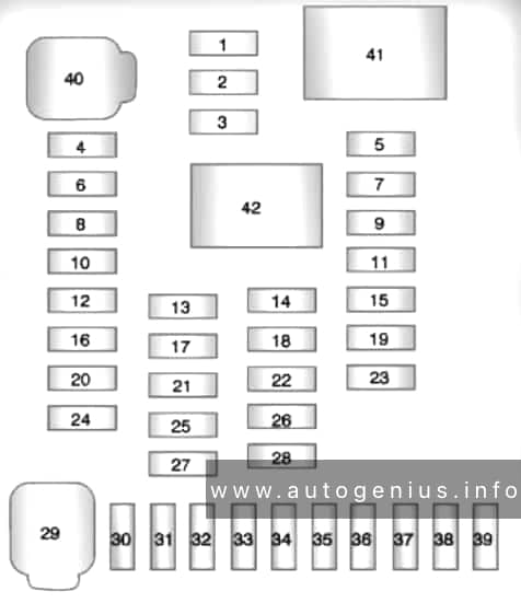
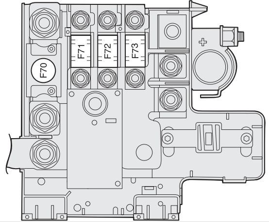
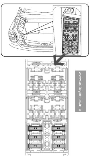
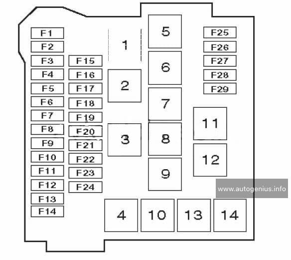
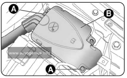
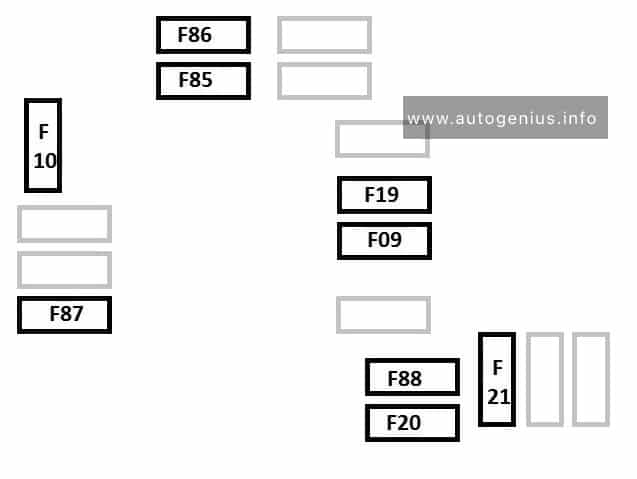
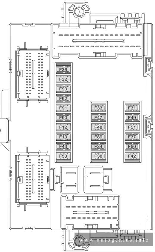
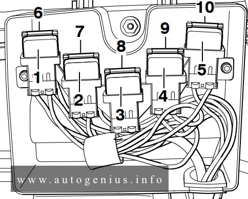
Main fuse box in luggage compartment, left – Main Fuses
Fuse box diagram
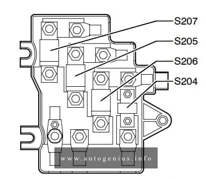
Assignment of the fuses in the luggage comparment
| Number | Ref. in wiring diagram | Amps | Function/Component | Terminal |
| 1 | S204 – Fuse -1- (30) | 100 | A18 – Windshield Heating Voltage Converter | 30 |
| 2 | S205 – Fuse -2- (30) | 150 | TV28- Wire junction 3 for terminal 30,
Thermofuses: SE1, SE2, SE3, SE4, SE5, SE6, SE7 Fuses: SB5, SB7 to SB18, SB27 to SB36, SD11, SD23, SD24, SD26, J329- Voltage Supply Terminal 15 (B+) Relay J680- Power Supply Relay 1 (terminal 75) |
30 |
| 3 | S206 – Fuse -3- (30) | 300 | Fuses: SC3, SC6, SC8 to SC16, SC23 to SC27, SC41 to SC47
C – Generator (GEN) |
30 |
| 4 | S207 – Fuse -4- (30) | — | Open | 30 |
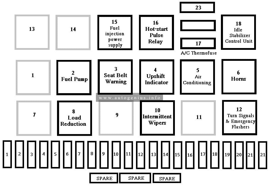
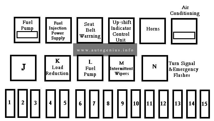
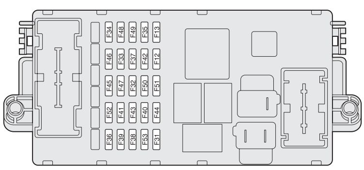
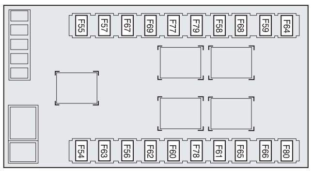
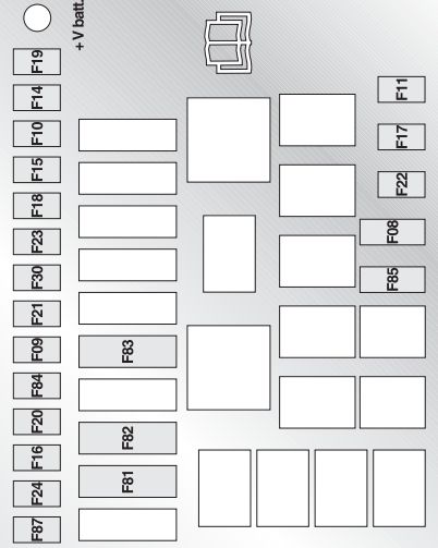
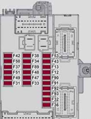
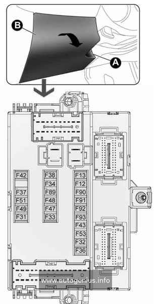
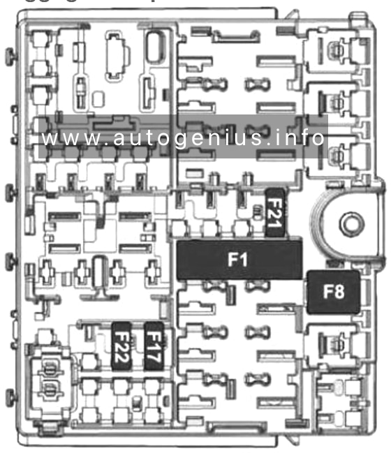
Fuse box under instrument panel, left – Fuses “SB”
Fuse box diagram
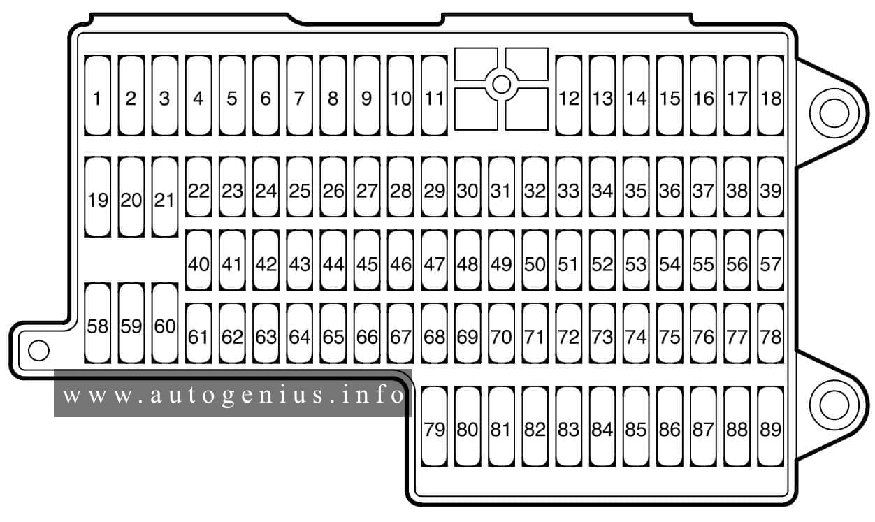
Assignment of the fuses in the passenger comparment
| Number | Ref. in wiring diagram | Amps | Function/Component | Terminal |
| 1 | SB1 – Fuse 1 (in fuse holder) | 10 | Terminal 30 for J582 – Wiper Park Position Heating Relay
Z 20 – Left Washer Nozzle Heater Z 21 – Right Washer Nozzle Heater |
75a |
| 2 | SB2 – Fuse 2 (in fuse holder) | 20 | J386 – Door control module, driver side
J657 – Door Closing Control Module J388 – Door control module, rear, left |
30 |
| 15* | ||||
| 3 | SB3 – Fuse 3 (in fuse holder) | 20 | J387 – Door control module, passenger side
J657 – Door Closing Control Module J389 – Door control module, rear, right |
30 |
| 15* | ||||
| 4 | SB4 – Fuse 4 (in fuse holder) | 20 | SC18 -Fuse 18 (in fuse holder)
SC19 -Fuse 19 (in fuse holder) SC20 -Fuse 20 (in fuse holder) |
15a |
| 5 | SB5 – Fuse 5 (in fuse holder) | 5 | J528 – Roof Electronics Control Module | 30 |
| 6 | Open | — | — | — |
| 7 | Open | 15 | — | 30 |
| 8 | SB 8 – Fuse 8 (in fuse holder) | 25 | J104 – ABS Control Module (w/EDL)
J106 – ABS Solenoid Valve Relay |
30 |
| 9 | Open | 5 | — | — |
| 10 | SB10 – Fuse 10 (in fuse holder) | 15 | J519 – Vehicle Electrical System Control Module
M5 – Left Front Turn Signal Light M1 – Left Parking Light |
30 |
| 11 | SB11 – Fuse 11 (in fuse holder) | 15 | J519 – Vehicle Electrical System Control Module
M7 – Right Front Turn Signal Light M3 – Right Parking Light |
30 |
| 12 | SB12 – Fuse 12 (in fuse holder) | 15 | J519 – Vehicle Electrical System Control Module
J567 – Left Headlight Range Control Module M29 – Left Low Beam Headlight J683 – Left HID Lamp High Beam Control Module M30 – Left High Beam Headlight |
30 |
| 13 | SB13 – Fuse 13 (in fuse holder) | 15 | J519 – Vehicle Electrical System Control Module
J568 – Right Headlight Range Control Module M31 – Right Low Beam Headlight J684 – Right HID Lamp Hight Beam Control Module M32 – Right High Beam Headlight |
30 |
| 14 | SB14 – Fuse 14 (in fuse holder) | 20 | J519 – Vehicle Electrical System Control Module
H1 – Signal horn/dual tone horn |
30 |
| 15 | SB15 – Fuse 15 (in fuse holder) | 15 | F – Brake Light Switch
J605 – Rear Lid Control Module J…- Engine Control Modlue (ECM) J345 – Control Module for towing sensor J104 – ABS Control Module (w/EDL) |
30 |
| 16 | SB16 – Fuse 16 (in fuse holder) | 20 | J162 – Heater Control Module | 30 |
| 17 | SB17 – Fuse 17 (in fuse holder) | 10 | J523 – Front Information Display Control Head Control Module
R 24 – Antenna Amplifier |
30a |
| 18 | SB18 – Fuse 18 (in fuse holder) | 10 | J527 – Steering Column Electronic Systems Control Module | 30a |
| 19 | SB19 – Fuse 19 (in fuse holder) | 10 | J518 – Access/Start Control Module | 30a |
| 20 | Open | — | — | — |
| 21 | Open | — | — | — |
| 22 | SB22 – Fuse 22 (in fuse holder) | 5 | J623 – Engine Control Module (ECM) (engine code BAP)
J623 – Engine Control Module (ECM) 2 (engine code BAP) J220 – Motronic Engine Control Module (ECM) (engine code BGJ) |
30a |
| 23 | SB23 – Fuse 23 (in fuse holder) | 5 | J285 – Control module with indicator unit in instrument panel insert | 30a |
| 24 | Open | — | — | — |
| 25 | Open | — | — | — |
| 26 | Open | — | — | — |
| 27 | SB27 – Fuse 27 (in fuse holder) | 5 | J285 – Control module with indicator unit in instrument panel insert Data Link Connector (DLC)
J669 – Seat Belt Tensioner Relay |
30a |
| 28 | SB28 – Fuse 28 (in fuse holder) | 5 | J526 – Telephone/Telematic Control Module | 30a |
| 29 | SB29 – Fuse 29 (in fuse holder) | 5 | R149 -Auxiliary Water Heating RF Receiver (where applicable) | 30a |
| 30 | SB30 – Fuse 30 (in fuse holder) | 10 | J255 – Climatronic Control Module
V 50 – Coolant Pump N175 -Left Heat Regulating Valve N176 – Right Heat Regulating Valve |
30a |
| 31 | SB31 – Fuse 31 (in fuse holder) | 5 | Y – Analog Clock/Control Module
J524 – Rear Information Display Control Head |
30a |
| 32 | Open | — | — | — |
| 33 | SB33 – Fuse 33 (in fuse holder) | J17 – Fuel Pump (FP) Relay
J271- Motronic Engine Control Module (ECM) Power Supply Relay J670- Motronic Engine Control Module (ECM) Power Supply Relay 2 J581- Parallel Battery Connection Relay (where applicable) J49 – Fuel Pump (FP) 2 Relay J220- Motronic Engine Control Module (ECM) (engine code BGJ) |
30 | |
| 34 | SC34 – Fuse 34 (in fuse holder) | 20 | G6 – Fuel Pump (FP) | 30 |
| 35 | SC35 – Fuse 35 (in fuse holder) | 20 | G23 – Transfer Fuel Pump (FP) | 30 |
| 36 | SC36 – Fuse 36 (in fuse holder) | 30 | Terminal 30 for J681 – Power Supply Relay 2 (terminal 15)
Fuses: SB52, SB53, SB54, SB55, SB56, SB57 |
30 |
| 37 | Open | — | — | — |
| 38 | Open | — | — | — |
| 39 | Open | — | — | |
| 40 | Open | — | — | — |
| 41 | SC41 – Fuse 41 (in fuse holder) | 5 | G384- Vehicle Inclination Sensor | 30 |
| 42 | SC42 – Fuse 42 (in fuse holder) | 5 | J393- Central control module for comfort system | 30 |
| 15* | ||||
| 43 | SC43 – Fuse 43 (in fuse holder) | 30 | J605- Rear Lid Control Module | 30 |
| 44 | SC44 – Fuse 44 (in fuse holder) | 10 | J197- Level Control System Control Module | 30 |
| 45 | SC45 – Fuse 45 (in fuse holder) | 5 | J697- License Plate Light Control Module
L153- Rear Illumination Lamp |
30 |
| 46 | Open | — | — | — |
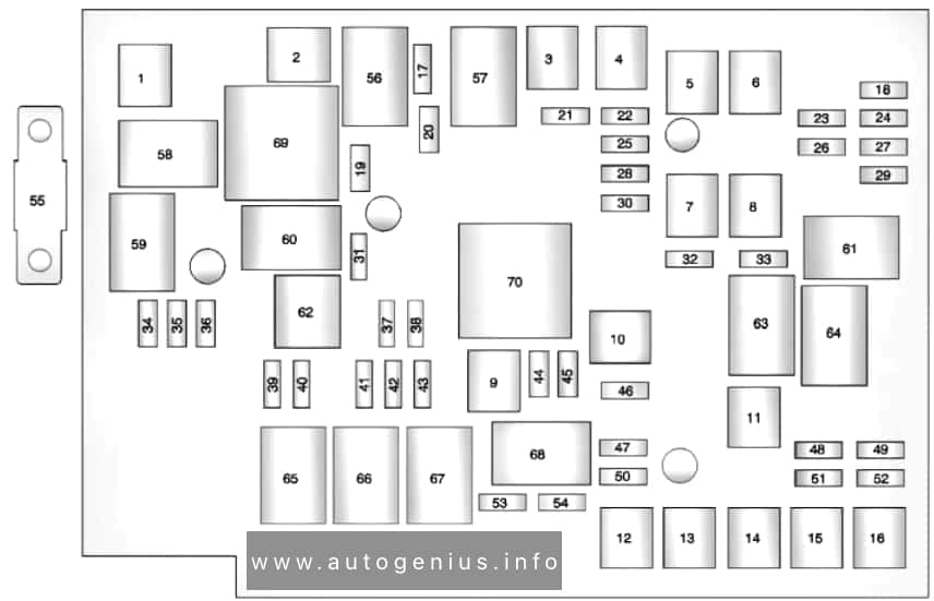
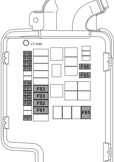
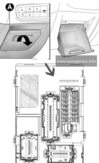
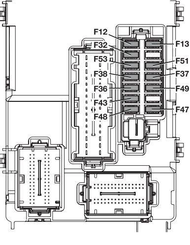
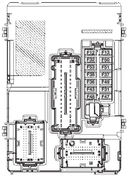
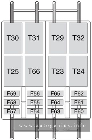
Electronics box in right plenum chamber – Relays
Fuse box diagram
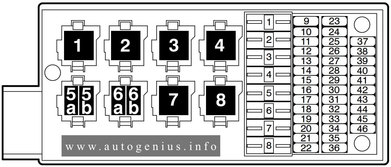
Assignment of the relay in the right plenum chamber
| Relay | Description |
| 1 | Open |
| 2 | C24 – Supressor |
| 3 | J682- Power Supply Relay (terminal 50) |
| 4 | J271 – Motronic Engine Control Module (ECM) Power Supply Relay (167) |
| 5 | J670 – Motronic Engine Control Module (ECM) Power Supply Relay 2 (100) (engine code BAP) |
| 5 | Open |
| 6 | J680 – Power Supply Relay 1 (terminal 75) (100) |
| 7 | J299 – Secondary Air Injection (AIR) Pump Relay (100) |
| 7 | Open |
| 8 | J329 – Voltage Supply Terminal 15 (B+) Relay (433) (where applicable) |
| 9 | J545 – Secondary Air Injection (AIR) Pump Relay 2 (100) (engine code BAP) |
| 9 | Open |
| 10 | Open |
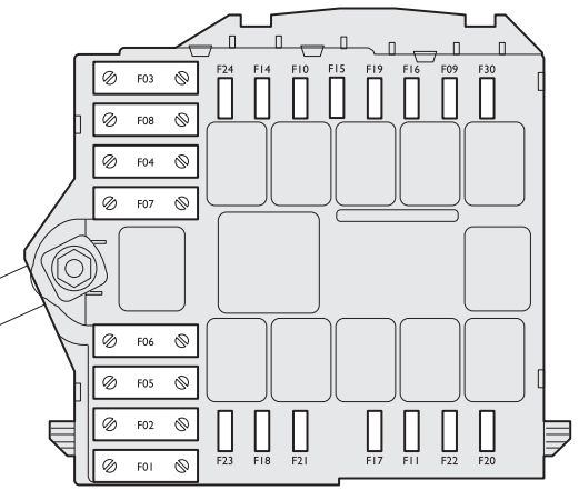
Electronics box in right plenum chamber – Fuses “SD”
Assignment of the relay in the right plenum chamber
| Number | Ref. in Wiring Diagram | Amps | Function/Component | Terminal |
| 1 | SD1 – Fuse 1 (in fuse holder) | 10 | N… – Fuel Injectors for cylinders 1 – 6 (engine code BAP) | 87a |
| 2 | SD2 – Fuse 2 (in fuse holder) | 10 | N… – Fuel Injectors for cylinders 7 – 12 (engine code BAP) | 87a |
| 3 | Open | 30 | Open | 30 |
| 4 | Open | 30 | Open | 30 |
| 5 | SD5 – Fuse 5 (in fuse holder) | 5 | G70 – Mass Air Flow (MAF) Sensor (engine code BAP)
G246- Mass Air Flow (MAF) Sensor 2 (engine code BAP) G42 – Intake Air Temperature (IAT) Sensor (engine code BAP) G299- Intake Air Temperature (IAT) Sensor 2 (engine code BAP) |
87a |
| 6 | SD6 – Fuse 6 (in fuse holder) | 10 | J496- Auxiliary Engine Coolant (EC) Pump Relay (engine code BAP)
V51 – After-Run Coolant Pump (engine code BAP) J299- Secondary Air Injection (AIR) Pump Relay J545- Secondary Air Injection (AIR) Pump Relay 2 (code BAP) J49 – Fuel Pump (FP) 2 Relay (engine code BAP) V36 – Coolant Pump (engine code BGJ) J151- Coolant Circulation Pump Relay (engine code BGJ) |
87a |
| 7 | SD7 – Fuse 7 (in fuse holder) | 20 | F265- Map Controlled Engine Cooling Thermostat (en-code BAP)
N80 – Evaporative Emission (EVAP) Canister Purge Regulator Valve N112- Secondary Air Injection (AIR) Solenoid Valve N145- Right Electro-Hydraulic Engine Mount Solenoid Valve (code BAP) N156- Intake Manifold Change-Over Valve (engine code BGJ) N205- Valve -1- for camshaft adjustment N208- Valve -2- for camshaft adjustment N261- Intake Manifold Tuning (IMT) Valve -2- (engine code BGJ) N318- Camshaft Adjustment Valve 1 (exhaust) (engine code BAP) N319- Camshaft Adjustment Valve 2 (exhaust) (engine code BAP) N320- Secondary Air Injection (AIR) Solenoid Valve 2 (en-code BAP) N333- Evaporative Emission (EVAP) Canister Purge Regulator Valve 2 (engine code BAP) |
87a |
| 8 | SD8 – Fuse 8 (in fuse holder) | 30 | N… – Ignition Coils with Power Output Stage for cylinders 1 – 8 (engine code BGJ) | 87a |
| 9 | SD9 – Fuse 9 (in fuse holder) | 20 | N… – Fuel Injectors for cylinders 1 – 8 (engine code BGJ) | 87a |
| 10 | SD10 – Fuse 10 (in fuse holder) | 10 | J623- Engine Control Module (ECM) (engine code BAP)
J624- Engine Control Module (ECM) 2 (engine code BAP) J220 – Motronic Engine Control Module (ECM) (engine code BGJ) |
87a |
| 11 | SD11 – Fuse 11 (in fuse holder | 15 | J39 – Relay for headlamp cleaning system | 30a |
| 12 | SD12 – Fuse 12 (in fuse holder) | 10 | J293- Coolant FC (Fan Control( (FC)) Control Module
V7 – Coollant Fan J671- Coolant FC (Fan Control) Control Module 2 V177- Coolant Fan 2 |
87a |
| 13 | SD13 – Fuse 13 (in fuse holder) | 25 | Z19 – Oxygen Sensor (O2S) Heater (engine code BAP)
Z28 – Oxygen Sensor (O2S) 2 Heater 2 (engine code BAP) Z29 – Oxygen Sensor (O2S) Heater 1 (behind Three Way Catalytic Converter (TWC)) (engine code BAP) Z30 – Oxygen Sensor (O2S) Heater 2 (behind Three Way Catalytic Converter (TWC)) (engine code BAP) |
87a |
| 14 | SD14 – Fuse 14 (in fuse holder) | 25 | Z19 – Oxygen Sensor (O2S) Heater (engine code BGJ)
Z28 – Oxygen Sensor (O2S) 2 Heater 2 (engine code BGJ) Z29 – Oxygen Sensor (O2S) Heater 1 (behind Three Way Catalytic Converter (TWC)) (engine code BGJ) Z30 – Oxygen Sensor (O2S) Heater 2 (behind Three Way Catalytic Converter (TWC)) (engine code BGJ) Z 62 – Oxygen Sensor (O2S) Heater 3 (engine code BAP) Z 63 – Oxygen Sensor (O2S) Heater 4 (engine code BAP) Z 64 – Oxygen Sensor (02S) Heater 3 (behind Three Way Catalytic Converter (TWC)) (engine code BAP) Z 65 – Oxygen Sensor (02S) Heater 4 (behind Three Way Catalytic Converter (TWC)) (engine code BAP) |
87a |
| 15 | SD15 – Fuse 15 (in fuse holder) | 15 | J217- Transmission Control Module (TCM) | 30a |
| 16 | SD16 – Fuse 16 (in fuse holder) | 10 | J539- Brake Booster Control Module | 30a |
| 17 | SD17 – Fuse 17 (in fuse holder) | 5 | J309 – Solar Cell Separation Relay | 30a |
| 18 | SD18 – Fuse 18 (in fuse holder) | 15 | J519 – Vehicle Electrical System Control Module
V248 – Left Headlight Washer Jet Motor V249 – Right Headlight Washer Jet Motor |
30a |
| 19 | SD19 – Fuse 19 (in fuse holder) | 20 | J400 – Control module for wiper motor
V216 – Left Windshield Wiper Motor V59 – Windshield and Rear Window Washer Pump |
30a |
| 20 | SD20 – Fuse 20 (in fuse holder) | 20 | J584 – Right Windshield Wiper Motor Control Module
V217 – Right Windshield Wiper Motor |
30a |
| 21 | SD21 – Fuse 21 (in fuse holder) | 60 | Vehicles with single battery system only:
SB19 -Fuse 19 (in fuse holder) SB20 -Fuse 20 (in fuse holder) SB22 -Fuse 22 (in fuse holder) SB23 -Fuse 23 (in fuse holder) Terminal 30 for J271 – Motronic Engine Control Module (ECM) Power Supply Relay |
30 |
| 22 | SD22 – Fuse 22 (in fuse holder) | 40 | SD1 – Fuse 1 (in fuse holder) (engine code BAP)
N… – Ignition Coils with Power Output Stage for cylinders 1 – 6 (engine code BAP |
87a |
| 23 | SD23 – Fuse 23 (in fuse holder) | 40 | Terminal 30 für J680 – Power Supply Relay 1 (terminal 75)
SB1 – Fuse 1 (in fuse holder) SB40 -Fuse 40 (in fuse holder) |
30 |
| 24 | SD24 – Fuse 24 (in fuse holder) | 40 | J104 – ABS Control Module (w/EDL) | 30a |
| 25 | SD25 – Fuse 25 (in fuse holder) | 40 | SD2 – Fuse 2 (in fuse holder) (engine code BAP)
N… – Ignition Coils with Power Output Stage for cylinders 7 – 12 (engine code BAP) |
87a |
| 26 | SD26 – Fuse 26 (in fuse holder) | 40 | Terminal 30 for J329 – Voltage Supply Terminal 15 (B+) Relay | 30a |
| 27 | SD27 – Fuse 27 (in fuse holder) | 50 | J293 – Coolant FC (Fan Control( (FC)) Control Module (left) | 30a |
| 28 | SD28 – Fuse 28 (in fuse holder) | 50 | J671- Coolant FC (Fan Control) Control Module 2 (right) | 30a |
| 29 | SD29 – Fuse 29 (in fuse holder) | 50 | V101- Secondary Air Injection (AIR) Pump Motor | 30a |
| 30 | SD30 – Fuse 30 (in fuse holder) | 30 | V189- Secondary Air Injection (AIR) Pump Motor 2 (engine code BAP) | 30a |
| 31 | SD31 – Fuse 31 (in fuse holder | 40 | V2 – Fresh Air BLower
J255- Climatronic Control Module Terminal 87 for J309 – Solar Cell Separation Relay |
30a |
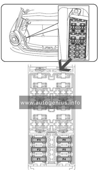
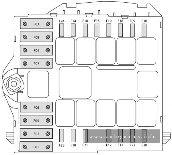
Thermofuse box in left front footwel – Thermofuses
Assignment of the fuses in the left front footwel
| No. | Ref. in wiring diagram | Amps | Function/component | Terminal |
| 1 | SE1 – Thermofuse 1 (on fuse holder) | 30 | J386- Door control module, driver side
J388- Door control module, rear, left |
30 |
| 2 | SE2 – Thermofuse 2 (on fuse holder | 30 | J387- Door control module, passenger side
J389- Door control module, rear, right |
30 |
| 3 | SE3 – Thermofuse 3 (on fuse holder) | 30 | J136- Memory Seat/Steering Column Adjustment Control Module | 30 |
| 4 | SE4 – Thermofuse 4 (on fuse holder) | 30 | J521- Passenger Memory Seat Control Module | 30 |
| 5 | SE5 – Thermofuse 5 (on fuse holder) | 30 | J522- Rear Memory Seat Control Module | 30 |
| 6 | SE6 – Thermofuse 6 (on fuse holder) | 30 | Z42 – Left Rear Footwell Heater | 30 |
| 7 | SE7 – Thermofuse 7 (on fuse holder) | 30 | Z43 – Right Rear Footwell Heater | 30 |
| 8 | Open | — | — | — |
| 9 | Open | — | — | — |
| 10 | Open | — | — | — |
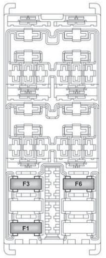
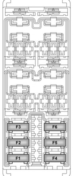
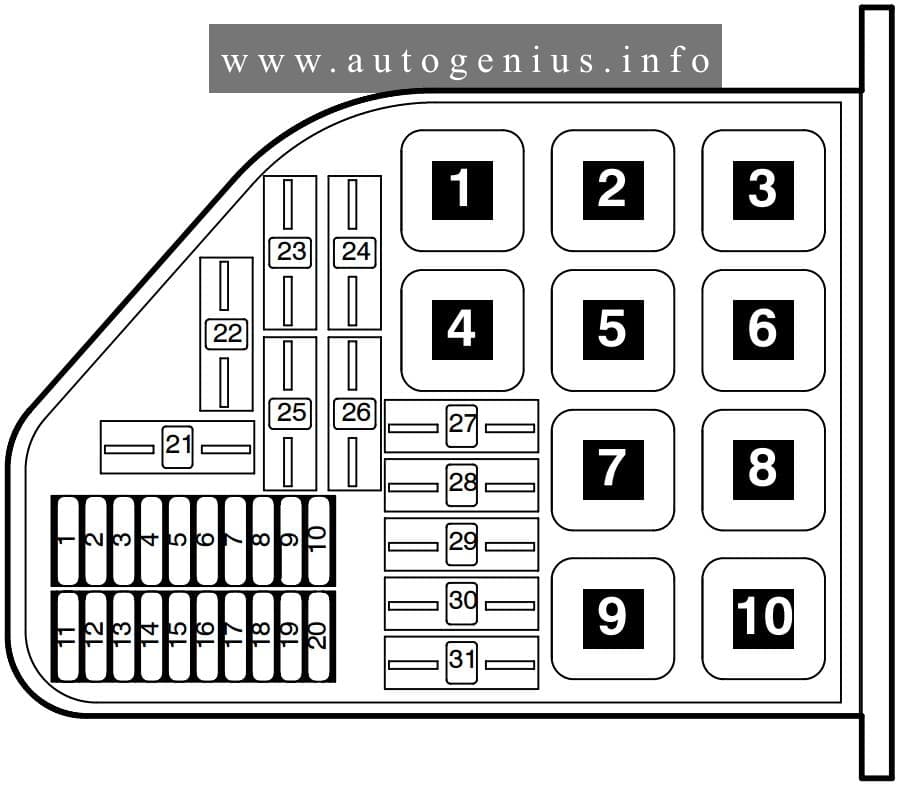
Relay panel in right front footwell – Relays
Assignment of the relays in the left front footwel
| Relay | Description |
| 1a | J496 – Auxiliary Engine Coolant (EC) Pump Relay (404) |
| 2b | Open |
| 2a | Open |
| 2b | Open |
| 3a | J582 – Wiper Park Position Heating Relay (404) |
| 3b | J709 – Seat Heater Authorization Relay (404) |
| 4 | J309 – Solar Cell Separation Relay (79) |
| 5 | J681 – Power Supply Relay 2 (terminal 15) (100) |
| 6 | J39 – Relay for headlamp cleaning system (53) |
| 7 | J236 – Servotronic Control Module (631) |
| 7 | Open |
| 8 | J669 – Seat Belt Tensioner Relay |
WARNING: Terminal and harness assignments for individual connectors will vary depending on vehicle equipment level, model, and market.