Chevrolet Astro (1996) – fuse and relay box diagram
Year of production: 1996
This article covers the Chevrolet Astro, produced from 1985 to 2005. It includes fuse box diagrams for the 1996 models, provides details on the location of the fuse panels inside the vehicle, and explains the function and layout of each fuse.
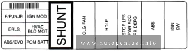
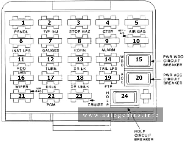
Passenger compartment
Fuse box location
The fuse block is located on the lower portion of the instrument panel on the driver’s side.
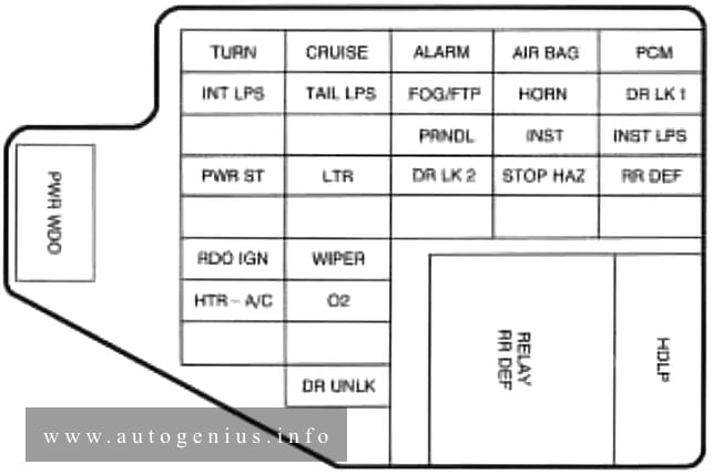
Fuse box diagram
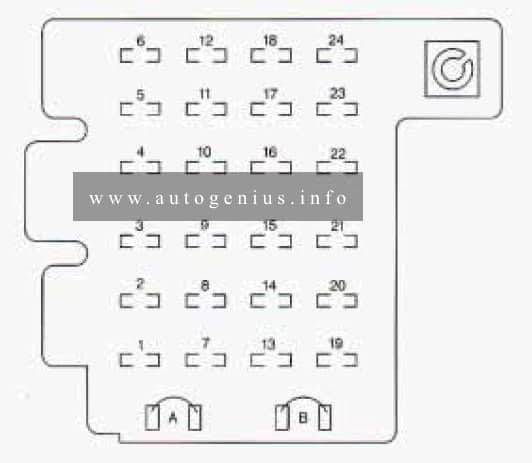
Assignment of the fuses in the passenger compartment (instrument panel)
| Fuses/Circuit Breaker | Usage |
| 1 | Stop/Tum/Hazard Lamps, CHMSL, Chime Module |
| 2 | No Fuse-Resistor |
| 3 | Courtesy Lamps, Power Outside Mirrors, Glove Box Lamp, Dome Reading Lamps, Vanity Mirror Lamps |
| 4 | DRL Relay, DRL Module, Chime Headlamp Switch, Keyless Entry, Cluster, Overhead Console |
| 5 | — |
| 6 | Cruise Module, Cruise Activator Switch |
| 7 | Power Outlets, DLC, Subwoofer Amplifier |
| 8 | — |
| 9 | License Plate Lamp, Taillamps, Parking Lamps, Ashtray Lamp, Panel Lights, Trailer Taillamps, Front and Rear Sidemarker Lamps, Door Switch Illumination, Headlamp Switch Illumination, RSA Illumination |
| 10 | Air Bag System |
| 11 | Wiper Motor, Washer Pump |
| 12 | L, M 1, M2 Blower Motor, Rear A/C Relay Coil, Front Cont, Temp. Door Motor, Hi Blower Relay, Defogger Timer Coil, Upfitter Relay Coil |
| 13 | Cigarette Lighter, Door Lock Relay |
| 14 | Cluster HVAC Controls, Chime Module, Radio Illumination, Rear Heat Switch Illumination, Rear WiperNasher Switch Illumination, Rear Liftgate Switch Illumination, Remote Cassette Illumination OH Console |
| 15 | DRL Lamps |
| 16 | Front Turn Signals, Rear Turn Signals, Trailer Turn Signals, Back-up Lamps, BTSI Solenoid |
| 17 | Radio: ATC (Standby), 2000 Series (Main Feed), Rear Seat Audio Controls |
| 18 | VCM-Ign 3, VCM- Brake, 4WAL, Cruise Stepper Motor |
| 19 | Radio: ATC (Main Feed), 2000 Series (Standby) |
| 20 | PRNDLI Odometer, TCC Enable and PWM Solenoids, Shift A and Shift B Solenoids, 3-2 Downshift Solenoids |
| 21 | — |
| 22 | — |
| 23 | Rear Wiper, Rear Washer Pump |
| 24 | — |
| A | (Circuit Breaker) Power Door Lock, 6-way Power Seat, Keyless Entry Module, Dutch Door Module, Dutch |
| B | (Circuit Breaker) Power Windows |
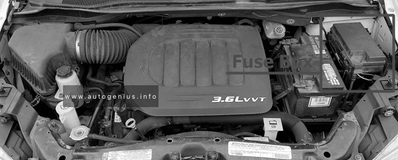
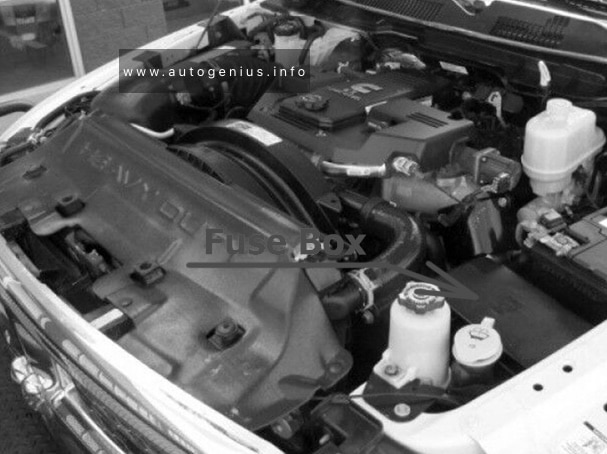
Engine compartment
Fuse box location
The underhood fuse block is located toward the rear of the engine compartment on the driver’s side of the vehicle.
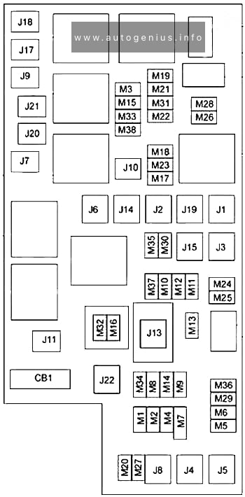
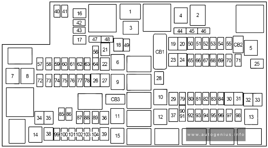
Fuse box diagram
Assignment of the fuses in the engine compartment
| Feef | Usage |
| AUX B | Upfitter Battery Feed |
| AUX A | Upfitter Accessory Feed |
| Relays |
| A/C Relay |
| IGN Relay |
| Starter Enable Relay |
| A/C Enable Relay |
| Empty Relay |
| Fuel Pump Relay |
| Fuse/Circuit Breaker | Usage |
| UPFITTER-BATT | Upfitter Battery Power Stud, Trailer Wiring Harness |
| UPFITTER-ACCY | Upfitter Accessory Relay |
| Spare | — |
| Fuse Puller* | |
| Spare | — |
| Spare | — |
| ECM-B | Fuel Pump Relay, VCM, Oil Pressure Switch/Sender |
| HORN | Horn Relay |
| A/C COMP | A/C Enable Relay |
| RR DEFOG | Heater-A/C Control Selector Switch |
| ENG-I | Oxygen Sensors 1-4, Camshaft Position Sensor, Mass Air Flow Sensor, Evaporative Emission Canister Purge Solenoid Valve, Linear EGR Valve Solenoid, VCM |
| IGN-E | A/C Enable Relay |
| ECM-I | Fuel Injectors 1-6, Crankshaft Position Sensor, VCM, Distributor Ignition Control Module |
| LIGHTING | Park Lamps Fuse, DRL Fuse, Headlamp and Panel Dimmer Switch |
| BATT I/P | Fuse Block Fuses, Power Seat CB, Stop/Hazard Fuse, Auxiliary Power Fuse, Cigarette Lighter Fuse, Radio, Battery Fuse |
| IGN A | Starter Relay, Ignition Switch |
| IGN B | Ignition Switc |
| ABS | Brake Pressure Module Valve |
| A/C | Blower Motor Resistor, Blower Relay |
| RR HTR/AC | Auxiliary Heater A/C Relay |
| Spare | Not Used |
| * A fuse puller is included in the underhood electrical center. You will also find spare fuses. | |
WARNING: Terminal and harness assignments for individual connectors will vary depending on vehicle equipment level, model, and market.