Buick Century (IV; 1978 – 1981) – fuse and relay box diagram
Year of production: 1978, 1979, 1980, 1981
This article covers the Buick Century. It includes fuse box diagrams for the 1978, 1979, 1980 and 1981 models, provides details on the location of the fuse panels inside the vehicle, and explains the function and layout of each fuse.
Fuse box diagram
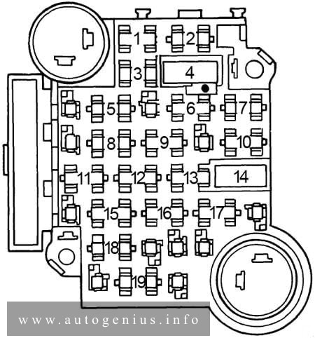
Buick Century (1978 – 1981) – fuse and relay box diagram
Assignment of the fuses in the fuse box diagram
Fuse
[A]
Protected Component
1
5
Instrument illumination and headlight warning
2
20
Electric choke (V6), closed loop
3
—
—
4
30
Circuit breaker: Power windows and roof
5
—
—
6
25
Heater, air conditioning, pulse wipers and deck lid
7
10
Electronic Control Module
8
—
—
9
25
Windshield wiper and washer
10
20
Hazard and stop lights
11
20
Seat belt light and buzzer, heated back light relay, tailgate window release, map light and fuel economy light
12
20
Tail, side marker, parking and license lights, clock radio
13
10
Radio
14
30
Circuit breaker: Power seats, door locks and heated back light
15
20
Turn signal and back-up lights
16
20
Clock, cigar lighter, glove box light, key buzzer, power antenna, clock radio, radio capacitor, dome and sail panel lights, trunk light, reading light, headlight on warning and door locks
17
—
—
18
—
—
19
10
Gauges, cruise control, torque converter clutch and indicator light
Circuit Breaker: Headlight Circuit — A thermo circuit breaker is incorporated in the headlight switch assembly to protect headlight circuits. Windshield Wiper — Integral with windshield wiper motor.
WARNING: Terminal and harness assignments for individual connectors will vary depending on vehicle equipment level, model, and market.
Year of production: 1989, 1990, 1991, 1992, 1993, 1994, 1995, 1996, 1997, 1998, 1999, 2000
This article covers the second-generation Iveco Daily II (2nd generation), produced from 1989 to 2000. It includes fuse box diagrams for the 1989, 1990, 1991, 1992, 1993, 1994, 1995, 1996, 1997, 1998, 1999 and 2000 models, provides details on the location of the fuse panels inside the vehicle, and explains the function and layout of each fuse.
Year of production: 2010 2011, 2012, 2013, 2014, 2015, 2016
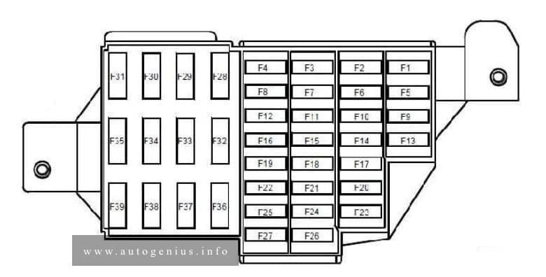
This article covers the first-generation Dacia Duster, produced from 2010 to 2016 It includes fuse box diagrams for the 2010, 2011, 2012, 2013, 2014, 2015 and 2016 models, provides details on the location of the fuse panels inside the vehicle, and explains the function and layout of each fuse.
Driver’s dual rear electric window control – child safety relay control
F14
30
Driver’s dual front electric window control
F15
10
Anti-lock braking system ECU
F16
15
Radio
F17
15
Main electromagnetic horn – secondary electromagnetic horn
F18
10
Rear left-hand side light – front left-hand side light
F19
10
Rear right-hand side light – passenger storage compartment light – instrument panel – UCH – hazard warning lights control – air conditioning control panel – radio – central door locking switch – first row cigarette lighter – 4×4 mode control – right-hand number plate light – left-hand number plate light – front right-hand side light – traction control switch – heated rear screen control – parking proximity sensor switch
F20
7,5
Rear fog light
F21
5
Instrument panel
F22
—
—
F23
15
Fuse on alarm version: Supply to horns via horn relay on board
F24
—
—
F25
—
—
F26
5
Airbag and pretensioner control unit
F27
20
Rear screen wiper motor – wash/wipe combination switch – reversing lights switch – neutral and reversing sensor on manual gearbox – automatic gearbox module – parking proximity sensor electronic control unit
F28
15
Consumer cut-out – instrument panel – radio – UCH
F29
15
UCH – diagnostic socket – anti-theft tracker unit
F30
20
UCH
F31
15
Supply to front right-hand and left-hand fog light via front fog relay on board – instrument panel indicator light
F32
30
heated rear screen switch
F33
—
—
F34
15
Front-rear torque distribution electric control unit
F35
—
—
F36
30
Cold air blower unit supply via cold air blower unit relay and air conditioning control panel
F37
5
Right-hand and left-hand electric door mirror supply via electric door mirror control
F38
15
Radio – first row cigarette lighter
F39
10
Cold air blower unit relay control
Relay box location
This relay is located in the passenger compartment, in the lower left-hand section of the dashboard
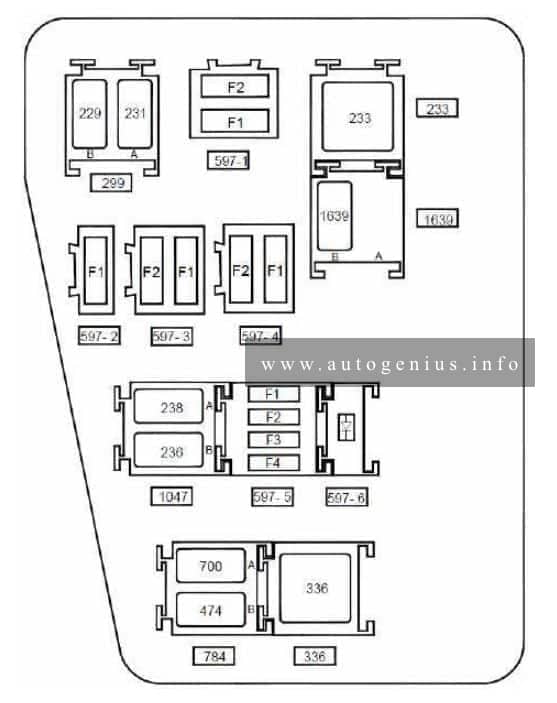
Anti-lock braking system electric control unit on versions without electronic stability program
F2
25
Anti-lock braking system electric control unit on versions without electronic stability program
Fuse board 597- 2
F1
40
Fuse on air conditioning version: Cooling fan assembly supply via fan assembly high-speed relay or via fan assembly low speed relay on relay board and fan assembly resistor – air conditioning clutch supply via air conditioning clutch relay on board
Fuse board 597- 3
F1
60
Ignition switch – monolever – supply to fuse F23 on passenger compartment fuse box
F2
60
Monolever supply – supply to fuses F29 and F36 on passenger compartment fuse box
Fuse board 597- 4
F1
—
—
F2
25
F34 fuse supply on passenger compartment fuse box on 4×4 version (four wheel drive)
Fuse board 597- 5
F1
30
Fuse on standard heating version: cooling fan assembly supply via low speed fan assembly relay on relay board
F2
25
Injection locking relay control and supply on relay board – fuel pump relay supply on relay board
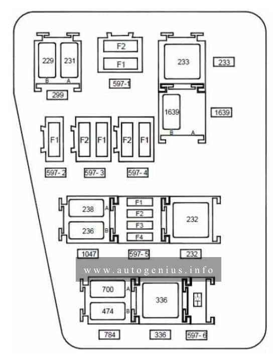
Anti-lock braking system electric control unit on versions without electronic stability program
F2
25
Anti-lock braking system electric control unit on versions without electronic stability program
Fuse board 597- 2
F1
40
Fuse on air conditioning version: cooling fan assembly supply via high speed fan assembly relay or via low speed fan assembly relay on relay board and fan assembly resistor
Fuse board 597- 3
F1
60
Ignition switch – monolever – supply to fuse F23 on passenger compartment fuse box
F2
60
Monolever supply – supply to fuses F29 and F36 on passenger compartment fuse box
Fuse board 597- 4
F1
—
—
F2
25
F34 fuse supply on passenger compartment fuse box on 4×4 version (four wheel drive)
Fuse board 597- 5
F1
15
Fuse on air conditioning version: Air conditioning clutch supply via air conditioning clutch relay on board
F2
25
Injection locking relay control and supply on relay board – fuel pump relay supply on relay board
F3
—
—
F4
15
Automatic gearbox electric control unit (119) with 4-speed automatic gearbox on F4R403 and F4R405 engines
Diode 597- 6 support plate
Diode
Air conditioning clutch
Relay board 299
A
20
Front fog lights
B
20
Horn
Unit relay 233
233
40
Cold air blower
Relay board 1047
A
20
Injection locking
B
20
Fuel pump
Relay board 784
A
20
Low speed fan assembly
B
20
Air conditioning clutch
Unit relay 336
336
40
High speed fan assembly
Unit relay 232 on automatic gearbox version
22
40
Starter
Relay 1639 board on FLEXFUEL version
A
—
—
B
20
Additional fuel pump
WARNING: Terminal and harness assignments for individual connectors will vary depending on vehicle equipment level, model, and market.
Fiat Ducato (III FL; 2014 – 2019) – fuse and relay box diagram
Year of production: 2014, 2015, 2016, 2017, 2018, 2019
This article covers the third-generation (3rd generation), produced from 2014 to present. It includes fuse box diagrams for the 2014, 2015, 2016, 2017, 2018 and 2019 models, provides details on the location of the fuse panels inside the vehicle, and explains the function and layout of each fuse.
Passenger compartment
Fuse box diagram
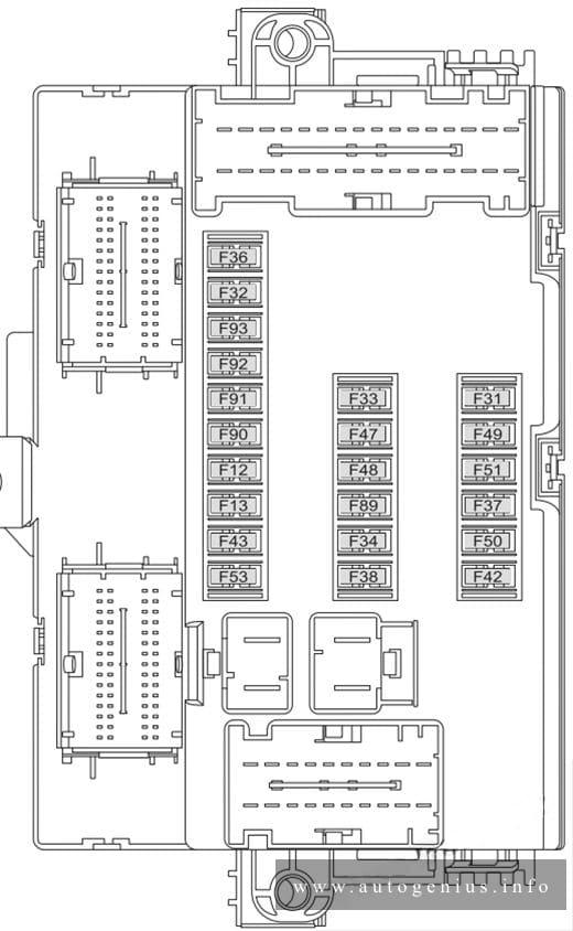
Fiat Ducato (III FL; 2014 – 2019) – fuse and relay box diagram – passenger compartment (dashboard)
Assignment of the fuses in the passenger compartment (dashboard)
№
Ampere rating [A]
Device protected
F12
7,5
Right dipped beam headlight
F13
7,5
Left dipped headlight
F31
5
Engine compartment control unit relay, dashboard control unit relay (+key)
F32
7,5
Lighting of roof lights in the passenger compartment (+battery)
F33
7,5
Battery monitoring sensor for Start&Stop versions (+battery)
F34
7,5
Minibus interior lights (emergency)
F35
7,5
Reversing lights, sevotronic control unit, Water in diesel fuel filter sensor, (+key)
F36
10
Radio, climate control, alarm, tachograph, battery disconnecting control unit, Webasto timer (+battery
F37
7,5
Brake light control (main), third brake light instrument panel (+key
F38
20
Door lock (+battery
F43
20
Windscreen wiper (+key)
F47
20
Driver’s side electric window
F48
20
Passenger side electric window
F49
5
Parking sensor control unit, radio, steering wheel controls, central control panel, left control panel, auxiliary panel, battery disconnecting control unit (+key
F51
5
Climate control, power steering control unit, reverse lights, diesel filter water sensor, flow meter, tachograph (+key)
F53
7,5
Instrument panel (+battery)
F89
—
—
F90
7,5
Left main beam headlight
F91
7,5
Right main beam headlight
F92
7,5
Left fog light
F93
7,5
Right fog light
Passenger compartment (optional fuse box)
Fuse box location
Optional fuse box on the right central post (where provided)
Fuse box diagram
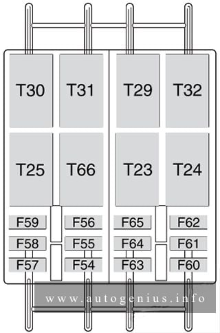
Fiat Ducato (III FL; 2014 – 2019) – fuse and relay box diagram – passenger compartment (optional)
Assignment of the fuses in the passenger compartment (optional fuse box)
№
Ampere rating [A]
Device protected
F54
—
—
F55
15
Heated seats
F56
15
Rear passenger power socket
F57
10
Additional heater under the seat
F58
10
Left heated rear window
F59
7,5
Right heated rear window
F60
—
—
F61
—
—
F62
—
—
F63
10
Additional passenger heater control
F64
—
—
F65
30
Additional passenger heater fan
Engine compartment
Fuse box diagram
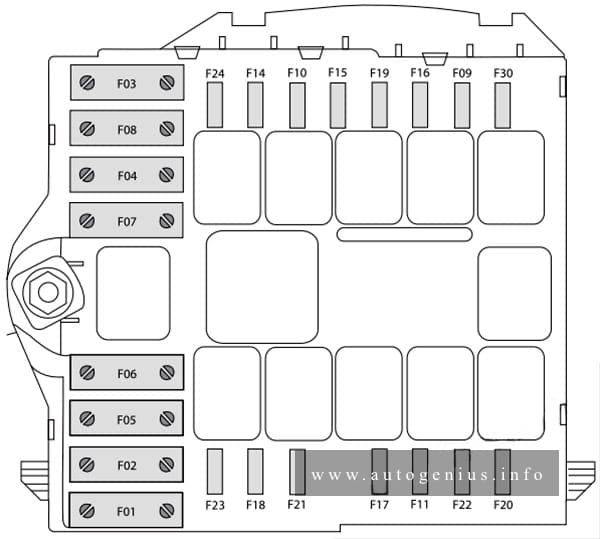
Fiat Ducato (III FL; 2014 – 2019) – fuse and relay box diagram – engine compartment
Assignment of the fuses in the engine compartment
№
Ampere rating [A]
Device protected
F03
30
Ignition switch (+battery)
F04
40
Heated filter
F05
20/50
Vaporiser for Puma engine/Passenger compartment ventilation with Webasto, robotised gearbox pump (+battery)
F06
40/60
Engine cooling high speed fan (+battery)
F07
40/50/60
Engine cooling low speed fan (+battery)
F08
40
Passenger compartment fan (+key
F09
15
Rear power socket (+battery)
F10
15
Horn
F14
15
Power socket (+battery)
F15
15
Cigar lighter (+battery)
F18
7,5
Powertrain Control Module, robotised gearbox control unit (+battery)
F19
7,5
Air conditioning compressor
F20
30
Windscreen wiper
F24
7,5
Auxiliary control panel for mirror movement and folding (+key)
F30
15
Mirrors demisting
WARNING: Terminal and harness assignments for individual connectors will vary depending on vehicle equipment level, model, and market.