Buick Century (VI; 1997 – 1999) – fuse and relay box diagram
Year of production: 1997, 1998, 1999
This article covers the Buick Century. It includes fuse box diagrams for the 6th generation 1997 models, provides details on the location of the fuse panels inside the vehicle, and explains the function and layout of each fuse.
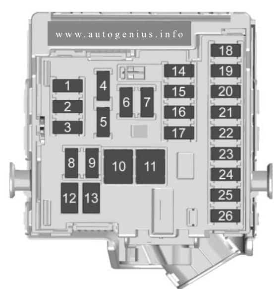
Passenger compartment
Fuse box location
The fuse box is located on right side of the instrument panel, behind the cover.
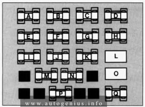
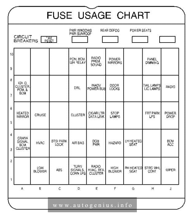
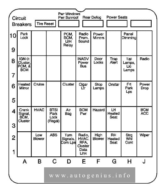
Fuse box diagram
Assignment of the fuses in the passenger compartment
| Circuit Breaker | Usage |
| A | — |
| B | Power Windows/Sunroof |
| C | Rear Defog |
| D | Power Seats |
| Fuse | Usage |
| 1 | — |
| 4 | Ignition Signal — Hot in Run and Start — PCM, BCM U/H Relay |
| 6 | Power Mirrors |
| 8 | Panel Dimming |
| 10 | Ignition Signal — Hot in Run, Unlock and Start — Cluster, Powertrain Control Module, Body Control Module |
| 13 | DRL Module |
| 14 | Interior Lamps |
| 15 | Door Locks |
| 17 | Taillamps, License Lamp |
| 18 | Radio |
| 19 | Heated Mirror |
| 20 | Cruise Control |
| 22 | Clusters |
| 23 | Cigarette Lighter — Auxiliary Power Connection, Data Link |
| 24 | Stoplamps |
| 26 | Parklamps |
| 27 | Auxiliary Power Connection — Hot in ACC and Run |
| 28 | Crank Signal — Body Control Module, Cluster, Powertrain Control Modules |
| 29 | Ignition Signal — HVAC Control Head |
| 30 | Brake Transmission Shift Interlock |
| 31 | Air Bag |
| 32 | Anti-lock Brake Controls, Body Control Module |
| 33 | Hazard Flashers |
| 34 | — |
| 36 | Ignition Signal — Hot in ACC and Run — Body Control Module |
| 37 | Anti-lock Brake Solenoids |
| 38 | Low Blowe |
| 39 | Anti-lock Brakes |
| 40 | Turn Signals |
| 41 | Radio, HVAC head, Keyless Entry, Cluster |
| 42 | High Blowe |
| 43 | — |
| 44 | Steering Wheel Controls |
| 45 | Wipers |
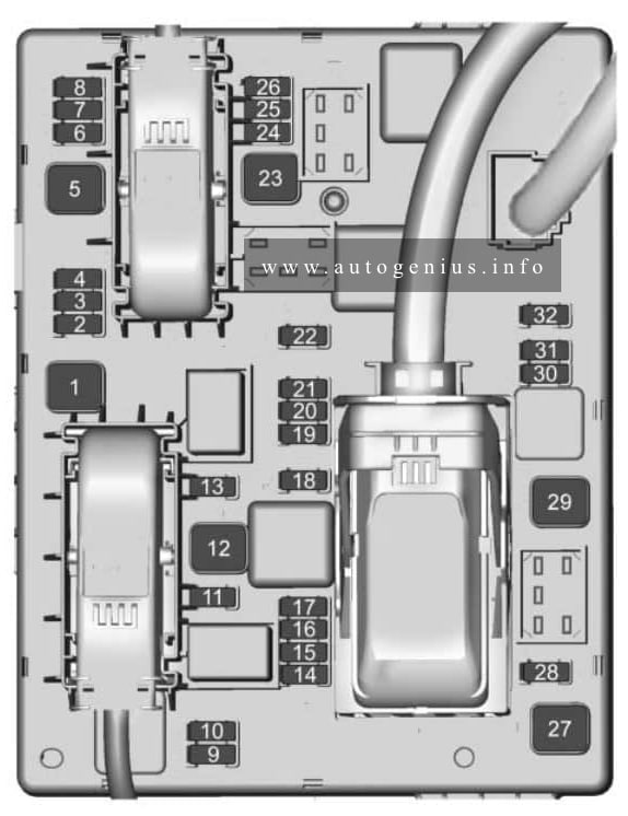
Engine compartment
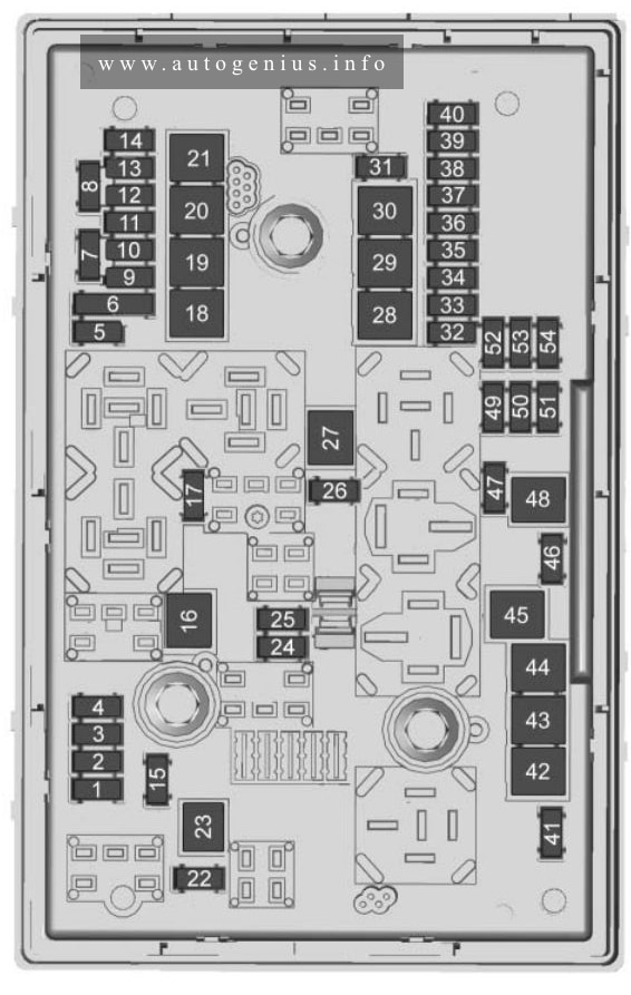
Fuse box diagram
Assignment of the fuses in the engine compartment
| Fuse | Usage |
| 1 | Cooling Fan |
| 2 | Starter Solenoid |
| 3 | Power Seats, Rear Defog |
| 4 | High Blower, Hazard Flasher, Stoplamps, Power Mirror, Door Locks |
| 5 | Ignition Switch, BTSI, Stoplamps, ABS, Turn Signals, Cluster, Air Bag, DRL Module |
| 6 | Cooling Fan |
| 7 | Interior Lamps, Retained Accessory Power, ABS, Keyless Entry, Data Link, HVAC Head, Cluster, Radio, AUX Power, Cigarette Lighter |
| 8 | Ignition Switch, Wipers, Radio, Steering Wheel Controls, Body Control Module, AUX Power, Power Windows, Sunroof, HVAC Controls, DRL, Rear Defog Relay |
| Relay | Usage |
| 9 | Cooling Fan 2 |
| 10 | Cooling Fan 3 |
| 11 | Starter Solenoid |
| 12 | Cooling Fan 1 |
| 13 | Ignition Main |
| 14 | — |
| Fuse | Usage |
| 15 | A/C Clutch |
| Relay | Usage |
| 16 | Horn |
| Fuse | Usage |
| 17 | — |
| 18 | — |
| 19 | Fuel Pump |
| 20 | Air Pump |
| 21 | Generator |
| 22 | ECM |
| 23 | A/C Compressor Clutch |
| 24 | — |
| 25 | Electronic Ignition |
| 26 | Transaxle |
| 27 | Horn |
| 28 | Fuel Injector |
| 29 | Oxygen Sensor |
| 30 | Engine Emissions |
| 31 | — |
| 32 | Headlamp (Right) |
| 33 | Rear Compartment Release |
| 34 | Parklamp |
| 35 | Fuel Pump |
| 36 | Headlamp (Left) |
| 37 | Spare |
| 38 | Spare |
| 39 | Spare |
| 40 | Spare |
| 41 | Spare |
| 42 | Spare |
| 43 | Fuse Puller |
| SYMBOL | A/C Commessor Clutch Diode |
WARNING: Terminal and harness assignments for individual connectors will vary depending on vehicle equipment level, model, and market.