Skoda CITIGOe iV (2019 – 2021) – fuse and relays box diagram
Year of production: 2019, 2020, 2021
The Škoda Citigoe iV (2019-2021) is Škoda’s first all-electric vehicle, designed as a compact city car. Based on the original Citigo, the electric version (Citigoe iV) was part of Škoda’s initiative to expand its electric vehicle lineup. This model is particularly suitable for urban commuting, thanks to its small size, eco-friendly nature, and practical design. Despite its compact build, it offers a comfortable and well-thought-out interior, combined with sufficient range for daily driving in and around cities.
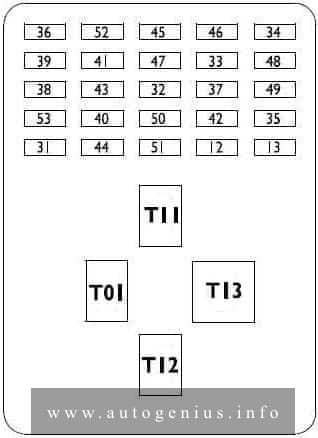
Passenger compartment fuse box
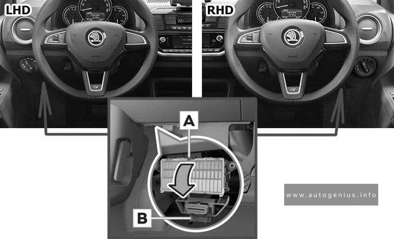
Fuse box location
The fuses are located underneath the steering wheel on the underside of the dash panel.
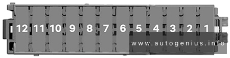
Fuse box diagram
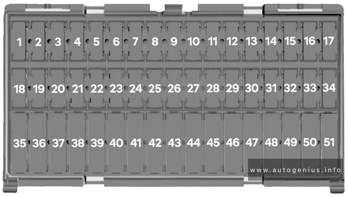
Assignment of the fuses below the instrument panel
| № | Amps | Function/component |
|---|---|---|
| 1 | 7.5A | Dash panel insert Engine control unit |
| 2 | 7.5A | High-voltage battery 1 Diagnostic connection |
| 3 | 7.5A | Rear view camera |
| 4 | – | – |
| 5 | 7.5A | Steering column electronics control unit Onboard supply control unit |
| 6 | 7.5A | Mirror adjustment switch Headlight range control regulator Left headlight range control motor Right headlight range control motor |
| 7 | 10A | Power and control electronics for electric drive |
| 8 | 7.5A | Selector lever Brake servo control unit Charge voltage control unit for high-voltage battery Power and control electronics for electric drive |
| 9 | 7.5A | Front passenger side airbag deactivated warning lamp Airbag control unit |
| 10 | 7.5A | Control unit for the parking aid |
| 11 | 7.5A | Front camera for driver assistance systems |
| 12 | – | – |
| 13 | – | – |
| 14 | 15A | Rear window wiper motor |
| 15 | 10A | Light switch |
| 16 | 7.5A | Terminal 15 voltage supply relay Power-assisted steering control unit |
| 17 | 15A | Steering column electronics control unit |
| 18 | 15A | Charging unit 1 for high-voltage battery |
| 19 | – | – |
| 20 | 7.5A | ABS control unit Steering column electronics control unit |
| 21 | – | – |
| 22 | – | – |
| 23 | 7.5A | Engine control unit |
| 24 | 15A | Steering column electronics control unit Headlight flasher switch |
| 25 | 10A | Windscreen and rear window washer pump |
| 26 | 7.5A | Main relay Dash panel insert |
| 27 | 7.5A | Onboard supply control unit Interior light |
| 28 | 7.5A | Diagnostic connection |
| 29 | 7.5A | Onboard supply control unit |
| 30 | 7.5A | Onboard supply control unit Heated exterior mirror on driver side Heated exterior mirror on passenger side |
| 31 | 10A | Radiator fan |
| 32 | 15A | Onboard supply control unit Turn signal/brake light |
| 33 | – | – |
| 34 | – | – |
| 35 | – | – |
| 36 | 20A | Cigarette lighter |
| 37 | 15A | Engine sound generator control unit |
| 38 | 20A | Radio |
| 39 | – | – |
| 40 | 15A | Engine control unit |
| 41 | 20A | Onboard supply control unit Central locking |
| 42 | 20A | Coolant pump for high-temperature circuit Coolant circulation pump upstream of power and control electronics for electric drive |
| 43 | 20A | Centre switch module in dash panel Centre switch module 2 in dash panel Heated front seats control unit |
| 44 | 7.5A | High-voltage battery 1 |
| 45 | 10A | Light switch |
| 46 | 30A | Onboard supply control unit Heated rear window |
| 47 | 30A | Front right window regulator switch Operating unit for window lifter in driver door (RHD) Driver side central locking lock unit |
| 48 | 20A | Onboard supply control unit High-frequency horn Low frequency horn |
| 49 | 30A | Onboard supply control unit Wiper motor control unit |
| 50 | 20A | Onboard supply control unit Left tail light cluster Left reversing light bulb Right tail light cluster Right reversing light bulb |
| 51 | 30A | Operating unit for window regulator in driver door Driver side central locking unit (RHD) |
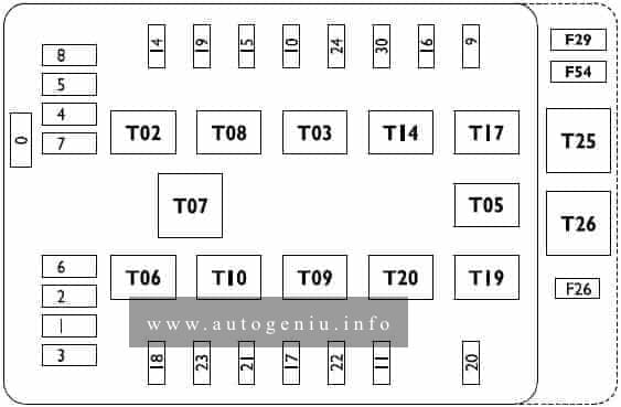
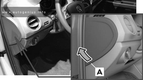
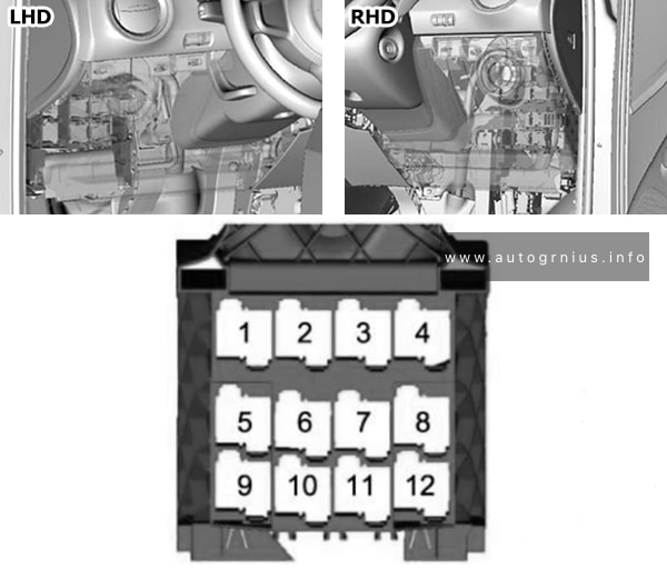
Fuses behind the side cover of the dash panel
Fuse box location
Fuse box diagram
Assignment of the fuses in the instrument panel
| № | Amps | Function/component |
|---|---|---|
| 1 | 7.5A | Control unit for emergency call module and communication unit |
| 2 | 30A | Brake system pressure accumulator |
| 3 | 7.5A | Solenoid valve for ignition key withdrawal lock |
| 4 | 20A | Blower relay |
| 5 | 7.5A | Climatronic relay |
| 6 | 10A | Emergency cut-out connection Maintenance connector for high-voltage system |
| 7 | 7.5A | Climatronic control unit |
| 8 | 7.5A | Selector lever Rain and light sensor Charge voltage control unit for high-voltage battery |
| 9 | 15A | Onboard supply control unit Low beam/daytime running lights/high beam |
| 10 | 15A | Onboard supply control unit Low beam/daytime running lights/high beam |
| 11 | 30A | Heated windscreen relay |
| 12 | 30A | Heated windscreen relay 2 |
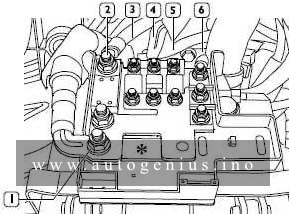
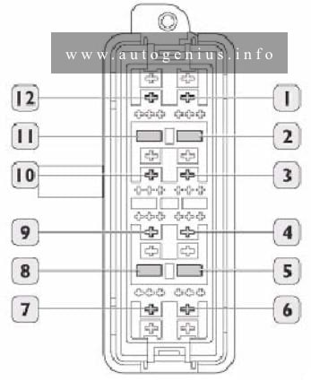
Relay panel
Fuse box location and diagram
Assignment of the fuses in the relay panel
| № | Relay |
|---|---|
| 1 | Terminal 75 voltage supply relay 1 |
| 2 | Terminal 15 voltage supply relay |
| 3 | Heated windscreen relay |
| 4 | Main relay |
| 5 | not assigned |
| 6 | Heated windscreen relay 2 |
| 7 | Climatronic relay |
| 8 | not assigned |
| 9 | not assigned |
| 10 | Blower relay |
| 11 | not assigned |
| 12 | not assigned |
Engine Compartment Fuse Box
Fuse Box Location
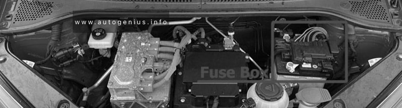
Fuse Box Diagram
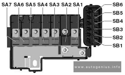
Assignment of the fuses in the engine compartment
| № | Amps | Function/component |
|---|---|---|
| SA1 | 250A | Power and control electronics for electric drive |
| SA2 | – | – |
| SA3 | 150A | Fuse holder C (below the instrument panel) Fuse holder D (at the end of the instrument panel) Terminal 15 voltage supply relay |
| SA4 | 50A | Power-assisted steering control unit |
| SA5 | 40A | ABS control unit |
| SA6 | 40A | Radiator fan |
| SA7 | 50A | Brake servo control unit |
| SB1 | 30A | ABS/ESC control unit |
| SB2 | 7.5A | Brake servo control unit |
| SB3 | 7.5A | Ignition starter switch / Control lever under the steering whee |
| SB4 | 10A | ABS/ESC control unit |
| SB5 | 7.5A | Battery monitor control unit Onboard supply control unit |
| SB6 | 30A | Ignition starter switch |
WARNING: Terminal and harness assignments for individual connectors will vary depending on vehicle equipment level, model, and market.