Chevrolet Equinox (2010 – 2017) – fuse and relay box diagram
Year of production: 2010, 2011, 2012, 2013, 2014, 2015, 2016, 2017
This article covers the second-generation Chevrolet Equinox, produced from 2010 to 2017. It provides fuse box diagrams for the 2010 through 2017 models, outlines the locations of the fuse panels within the vehicle, and explains the purpose and layout of each fuse and relay.
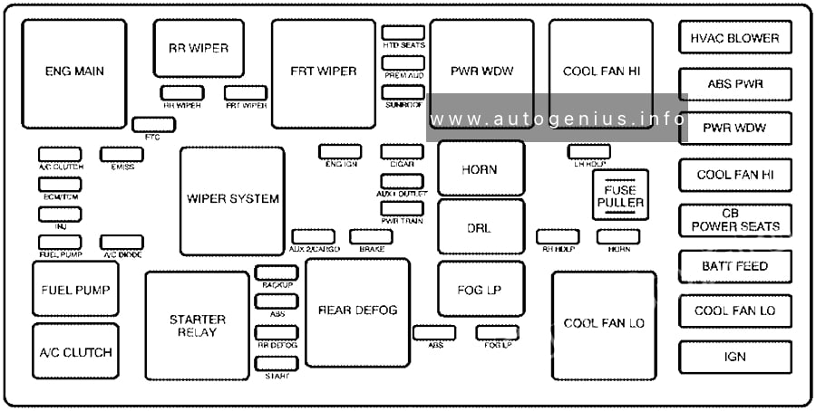
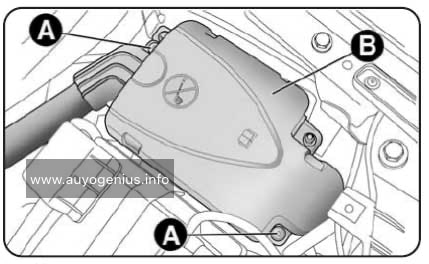
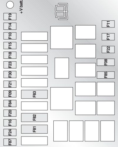
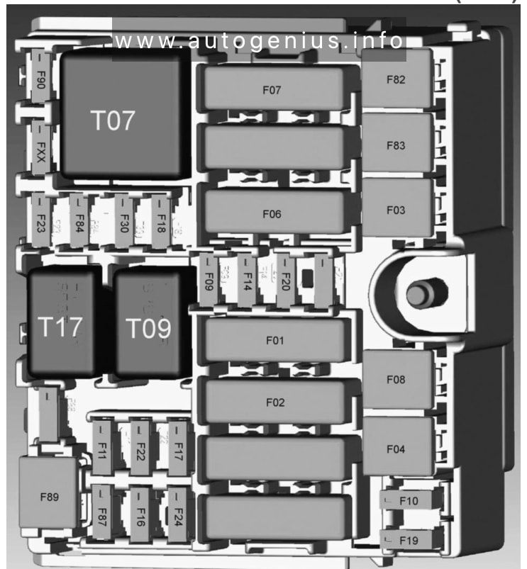
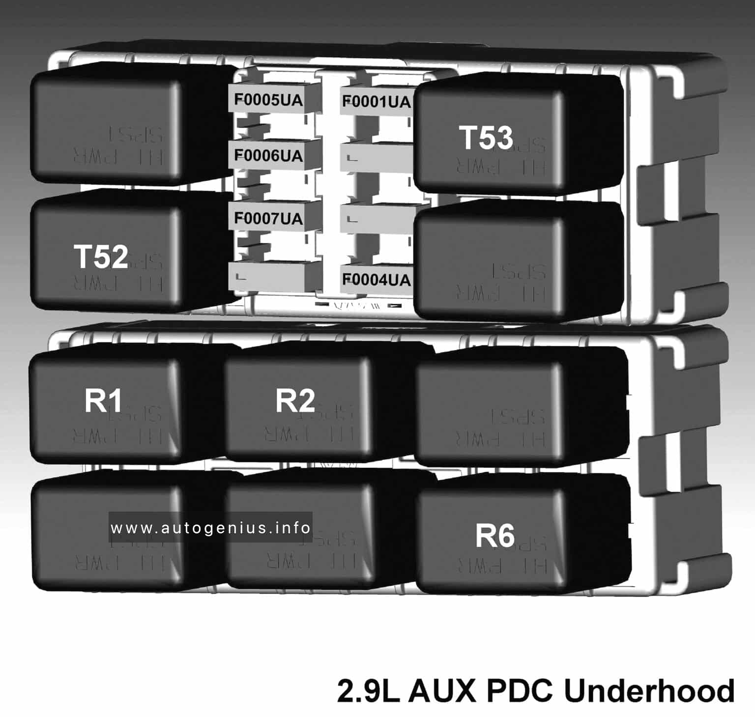
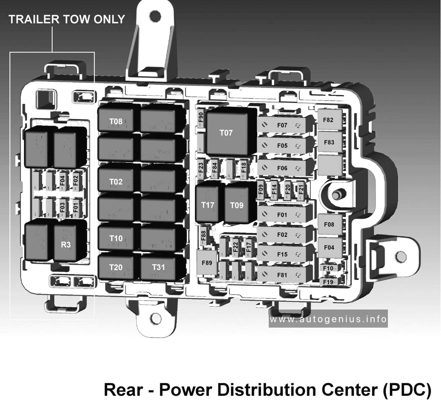
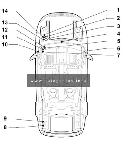
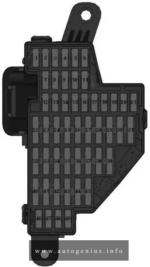
Engine compartment
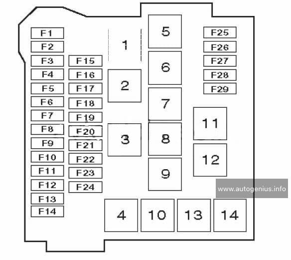
Fuse box diagram
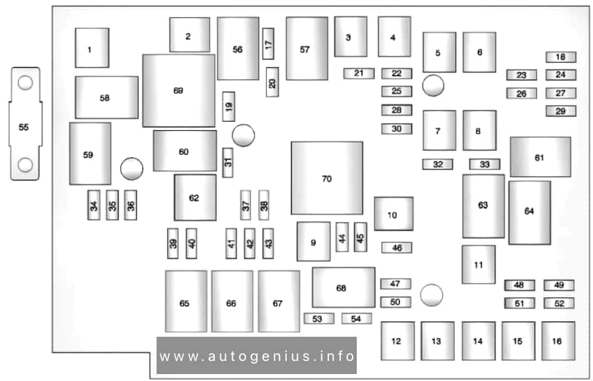
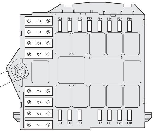
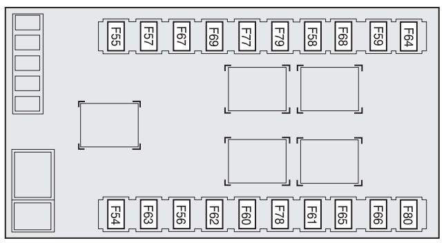
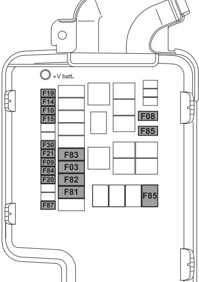
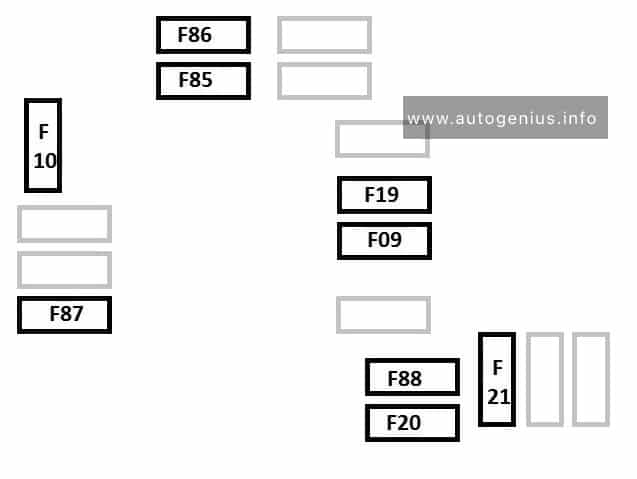
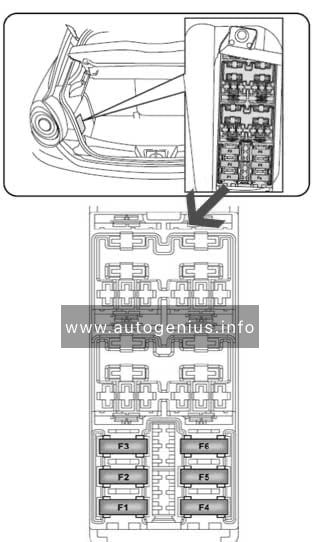
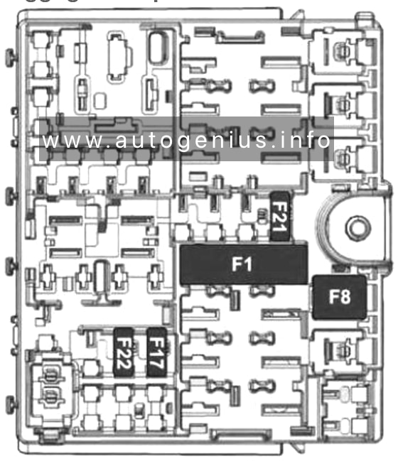
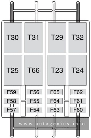
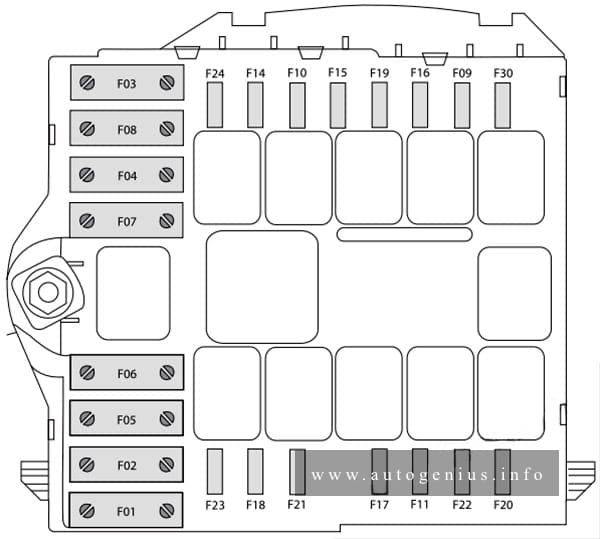
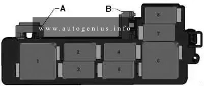
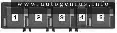
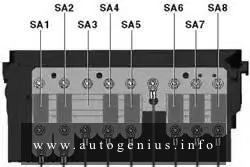
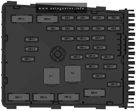
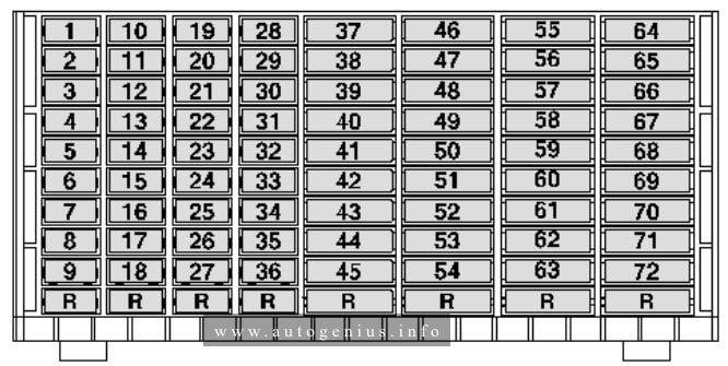
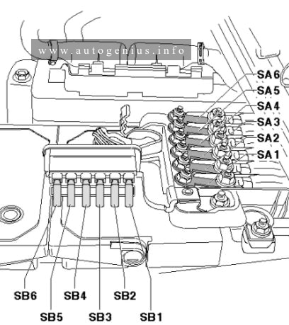
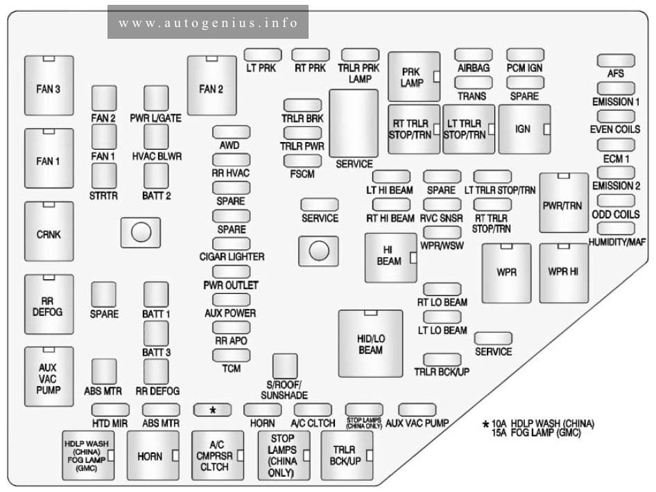
Assignment of the fuses and relay in the engine compartment
| № | Usage |
|---|---|
| 1 | Cool Fan 1 |
| 2 | Cool Fan 2 |
| 3 | Brake Booster |
| 4 | Power Windows -Right |
| 5 | Memory Seat Module |
| 6 | Power Seat – Left |
| 7 | Instrument Panel Fuse Block 1 |
| 8 | Rear Defogger |
| 9 | Starter |
| 10 | AIR Pump Motor |
| 11 | Instrument Panel Fuse Block 2 |
| 12 | Sunroof |
| 13 | Antilock Brake System Pump |
| 14 | Instrument Panel Fuse Block 3 |
| 15 | Power Windows – Left |
| 16 | Antilock Brake System Module |
| 17 | Transmission Control Module Battery |
| 18 | Trailer Parking Light |
| 19 | AIR Pump Solenoid |
| 20 | Engine Control Module Battery |
| 21 | Canister Vent |
| 22 | Trailer Left Side (If Equipped) |
| 23 | Lift Gate Module |
| 24 | Power Lumbar |
| 25 | Trailer Right Side (If Equipped) |
| 26 | Rear Accessory Power Outlet |
| 27 | Memory Mirror Module |
| 28 | Regulated Voltage Control Battery Sensor |
| 29 | Front Wiper |
| 30 | Rear Wiper |
| 31 | Air Conditioning Compressor |
| 32 | Rear Latch |
| 33 | Heated Mirrors |
| 34 | Horn |
| 35 | Right High-Beam Headlamp |
| 36 | Left High-Beam Headlamp |
| 37 | Ignition Even Coil |
| 38 | Ignition Odd Coil |
| 39 | Windshield Washer |
| 40 | Front Fog Lamps |
| 41 | Post Catalytic Converter Oxygen Sensor |
| 42 | Engine Control Module |
| 43 | Pre-Catalytic Converter Oxygen Sensor |
| 44 | Transmission Control Module |
| 45 | Mirror |
| 46 | Fuel System Control Module Ignition |
| 47 | Spare |
| 48 | Rear Drive Module |
| 49 | Lift Gate Module Logic |
| 50 | Instrument Panel Fuse Block Ignition |
| 51 | Heated Seat- Front |
| 52 | Fuel System Control Module |
| 53 | Engine Control Module |
| 54 | Rear Vision Camera |
| 55 | Electric Power Steering |
| 56 | AIR Pump Solenoid |
| 57 | Brake Booster |
| 58 | Cooling Fan Low |
| 59 | Headlamp High Beam |
| 60 | Cooling Fan Control |
| 61 | Wiper On/Off Control |
| 62 | Air Conditioning Compressor |
| 63 | Rear Defogger |
| 64 | Wiper Speed |
| 65 | Fog Lamp |
| 66 | Engine Control |
| 67 | Starter |
| 68 | Run/Crank |
| 69 | Cooling Fan High |
| 70 | AIR Pump Motor |
| 77 | Power Seat – Right |
| 78 | Passenger Power Lumber |
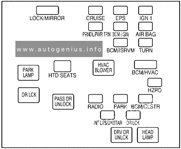
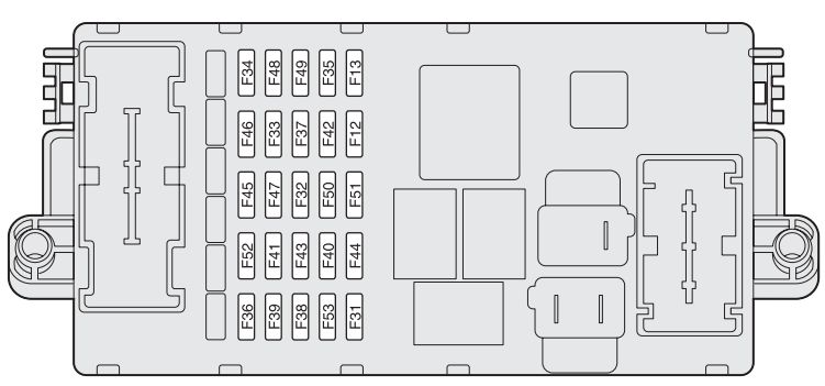
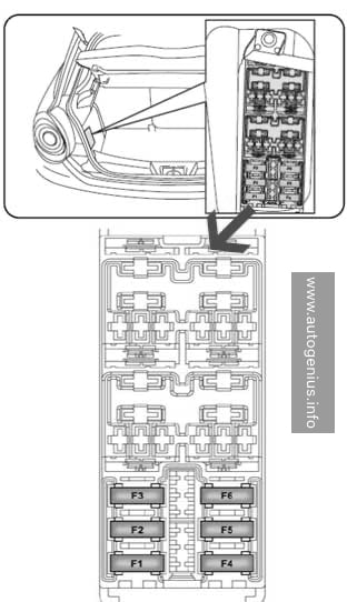
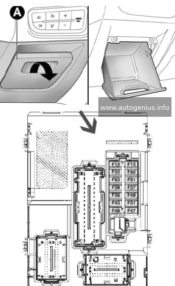
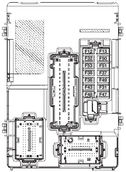
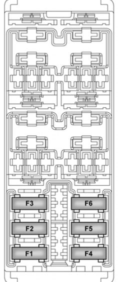
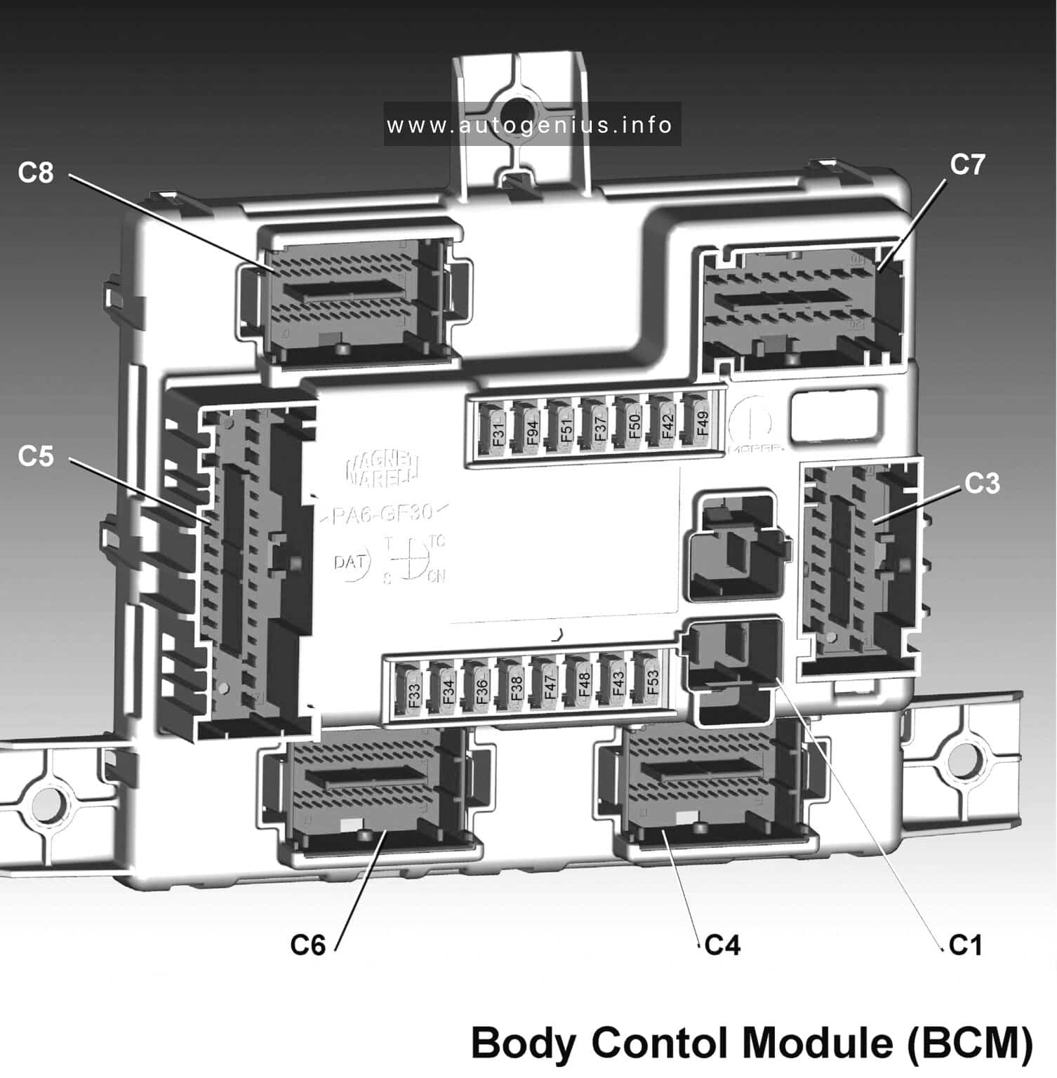
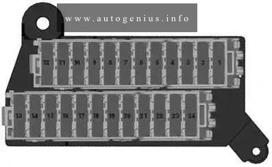
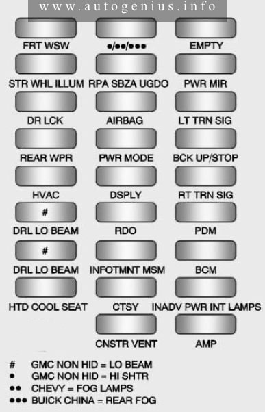
Instrument panel fuse block
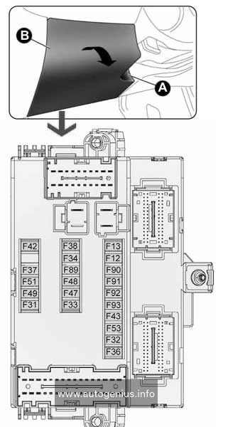
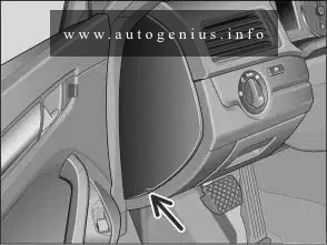
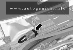
Fuse Box Location
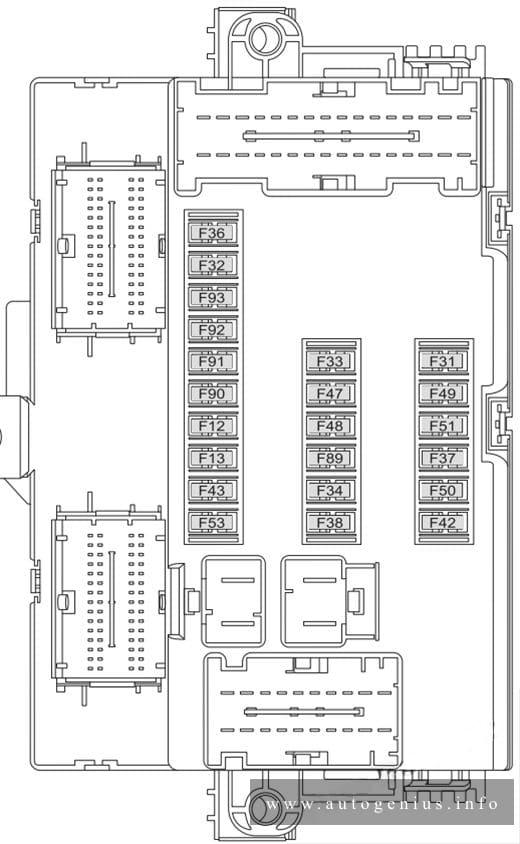
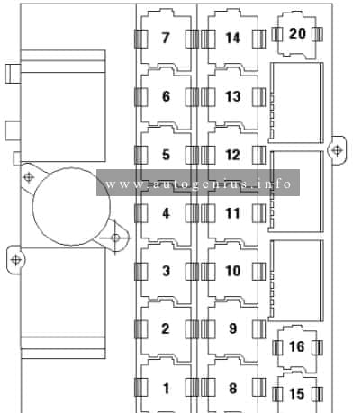
The instrument panel fuse block is located on the passenger side panel of the center console.
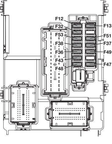
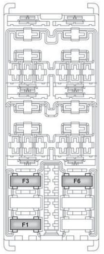
Fuse box diagram
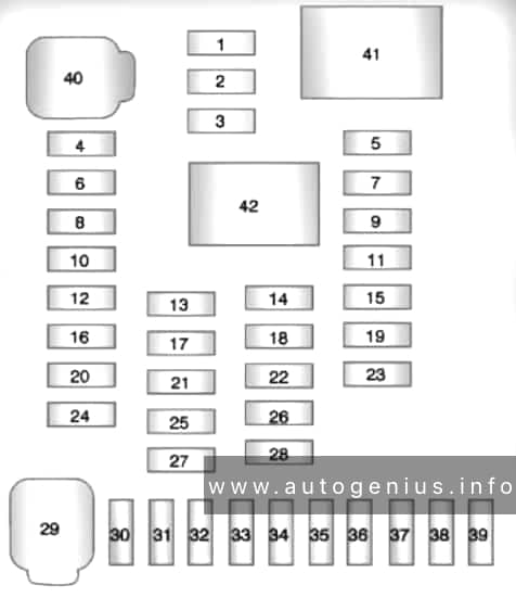
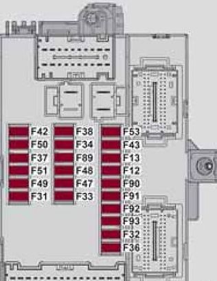
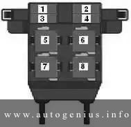
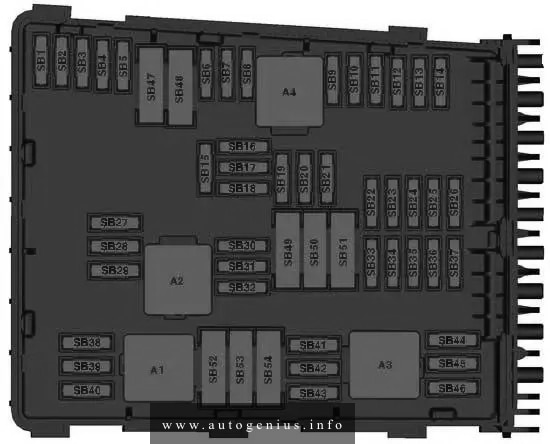
Assignment of the fuses and relay in the instrument panel
| № | Usage |
|---|---|
| 1 | Steering Wheel Dimming |
| 2 | Spare |
| 3 | Spare |
| 4 | Body Control Module 1 |
| 5 | Infotainment |
| 6 | Body Control Module 7 |
| 7 | Noise Control Module |
| 8 | Body Control Module 4 |
| 9 | Radio |
| 10 | Spare |
| 11 | Rear Parking Assist Module |
| 12 | Heater, Ventilation, and Air Conditioning Battery |
| 13 | Auxiliary Power Front |
| 14 | Heater, Ventilation and Air Conditioning Ignition |
| 15 | Display |
| 16 | Body Control Module 5 |
| 17 | Auxiliary Power Rear |
| 18 | Instrument Panel Ignition |
| 19 | Universal Garage Door Opener |
| 20 | Body Control Module 6 |
| 21 | Spare |
| 22 | Sensing and Diagnostic Module Ignition |
| 23 | Front Camera |
| 24 | Spare |
| 25 | Transmission Gear Shift Position Indicator |
| 26 | Spare |
| 27 | Spare |
| 28 | Spare |
| 29 | Front Blower Motor |
| 30 | Body Control Module 3 |
| 31 | Amplifier |
| 32 | Discrete Logic Ignition Switch |
| 33 | Communications Integration Module |
| 34 | Body Control Module 2 |
| 35 | Sensing and Diagnostic Module Battery |
| 36 | Data Link Connection |
| 37 | Instrument Panel Battery |
| 38 | Passenger Sensing System Module |
| 39 | Spare |
| 40 | Body Control Module 8 |
| 41 | Logistic Relay (If Equipped) |
| 42 | Retained Accessory Power Relay |
WARNING: Terminal and harness assignments for individual connectors will vary depending on vehicle equipment level, model, and market.