Honda Prelude (1997 – 2001) – fuse and relay box diagram
Year of production: 1997, 1998, 1999, 2000, 2001
This article focuses on the fifth-generation Honda Prelude (BB5–BB9), manufactured between 1996 and 2001. It includes fuse box diagrams for the 1997, 1998, 1999, 2000, and 2001 models, along with information on the location of the fuse panels inside the vehicle and details about each fuse’s function (fuse layout).
Passenger Compartment Fuse Box
Fuse Box Location
The interior fuse box is underneath the dashboard on the driver’s side. To open it, turn the knob as shown.
Fuse Box Diagram
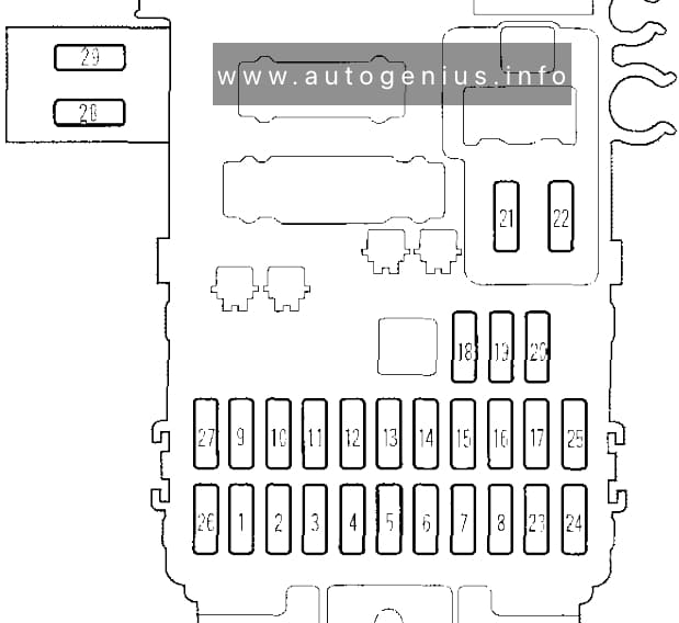
Assignment of the fuses in the instrument panel
| Number | Fuse name | Ampere rating [A] | Circuit protected |
| 1 | (ATTS UNIT) | 10 | Active Torque Transfer System Unit (Type SH) |
| 2 | STARTER SIGNAL | 7,5 | PGM-FI main relay, ECM, Starting system |
| 3 | — | — | — |
| 4 | ACG-S | 10 | PGM-FI main relay, Immobilizer control unit |
| 5 | (RR SPEAKER) | 10 | Stereo amplifier |
| 6 | (HEATED SEAT) | 15 | Seat heaters (Canada) |
| 7 | (SUN ROOF) | 30 | Moonroof |
| 8 | (DAY LIGHT) | 7,5 | Daytime running lights control unit (Canada) |
| 9 | R/C MIRROR (ABS, ATTS) |
7,5 | ABS system, Mirror defoggers (Canada), Power mirrors, Seat heaters (Canada), Blower motor relay, Option connector C982, ATTS system |
| 10 | TAIL LIGHT | 15 | Console lights, Dash lights, Parking lights, Rear side marker lights, Taillights, Security system (Canada) |
| 11 | REAR DEFROSTER RELAY | 7,5 | Rear window defogger relay |
| 12 | (DAY LIGHT UNIT) | 7,5 | Daytime running lights control unit (Canada) |
| 13 | METER (CRUISE CONTROL) |
15 | Turn signal lights, Hazard warning lights, Back-up lights, Cruise control, Clock, Gauge assembly, Driver’s multiplex control unit |
| 14 | ECU EAT ECU |
15 | Charging system, Vehicle speed sensor (VSS), TCM, PGM-FI, Immobilizer system (early production ’97 Model), Interlock system, Gauge assembly, Security system (Canada) |
| 15 | P/W DRIVER | 20 | Master power window switch/motor |
| 16 | P/W ASSISTANT | 20 | Passenger’s power window switch/motor |
| 17 | WIPER | 30 | Windshield wiper motor, Windshield intermittent wiper relay, Windshield washer switch |
| 18 | ACC | 7,5 | Stereo sound system, Accessory power socket relay, Interlock system |
| 19 | — | — | — |
| 20 | — | — | — |
| 21 | Fuel Pump | 15 | Fuel Pump |
| 22 | SRS | 10 | SRS |
| 23 | 15 | SRS unit | |
| 24 | 10 | SRS unit | |
| 25 | 10 | Spare Fuse | |
| 26 | 20 | Spare Fuse | |
| 27 | 30 | Spare Fuse | |
| 28 | 7,5 | Active Torque Transfer System (Type SH) | |
| 29 | — | — | — |
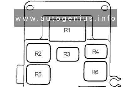
| R1 | Turn Signal/Hazard Relay | ||
| R2 | Moonroof Close Relay | ||
| R3 | Blower Motor Relay | ||
| R4 | Power Window Relay | ||
| R5 | Moonroof Open Relay | ||
| R6 | Rear Window Defogger Relay | ||
Fusebox in engine compartment
Fuse Box Location
The under-hood fuse box is located in the back of the engine compartment on the passenger’s side.
Fuse Box Diagram
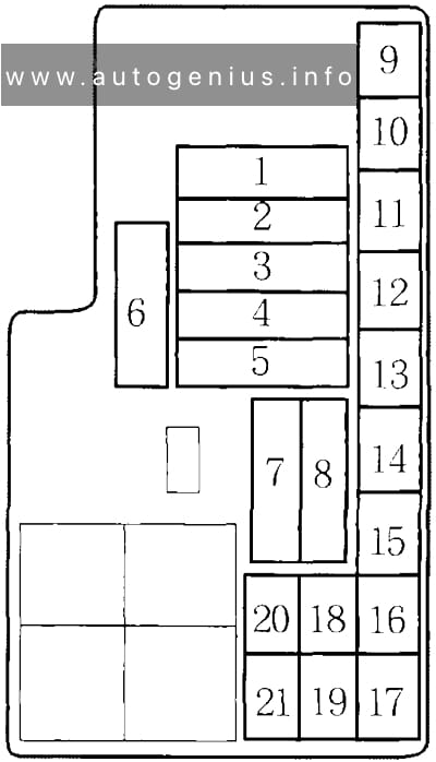
Assignment of the fuses in the engine compartment
| № | Amps | Circuits Protected |
|---|---|---|
| 1 | 40A | Main Fuse (Power Window) |
| 2 | 50A | Main Fuse (Fuse Box) |
| 3 | 40A | Main Fuse (Heater Motor) |
| 4 | 40A | Main Fuse (Rear Defroster) |
| 5 | 50A | Main Fuse (Ignition Switch) |
| 6 | – | Not Used |
| 7 | 100A | Main Fuse (Battery) |
| 8 | 30A | Main Fuse (ABS Motor) |
| 9 | 20A | Cooling Fan |
| 10 | 15A | Interior Lights |
| 11 | 20A | Condenser Fan |
| 12 | 10A | Door Lock |
| 13 | 7.5A | Clock, Radio |
| 14 | 20A | Small Light |
| 15 | 15A | Stop, Horn |
| 16 | 20A | ABS +B |
| 17 | 10A | Hazard |
| 18 | – | Not Used |
| 19 | 7.5A | ABS Unit |
| 20 | 20A | Left Headlight |
| 21 | 20A | Right Headlight |
WARNING: Terminal and harness assignments for individual connectors will vary depending on vehicle equipment level, model, and market.