Years of production: 1990, 1991, 1992, 1993, 1994, 1995, 1996, 1997
The Volkswagen Taro, a pickup truck, was produced from 1989 to 1997. This article includes fuse box diagrams for the 1990 through 1997 models, provides details on the locations of the fuse panels inside the vehicle, and explains the function of each fuse and relay (fuse layout).
Year of production: 1989, 1990, 1991, 1992, 1993, 1994, 1995, 1996, 1997
This article covers the first-generation Mazda MX-5 Miata (NA), produced between 1989 and 1997. It includes fuse box diagrams for the 1989–1997 models, provides details on the locations of the fuse panels inside the vehicle, and explains the function and layout of each fuse and relay.
Year of production: 1988, 1989, 1990, 1991, 1992, 1992, 1993, 1994, 1995, 1996, 1997
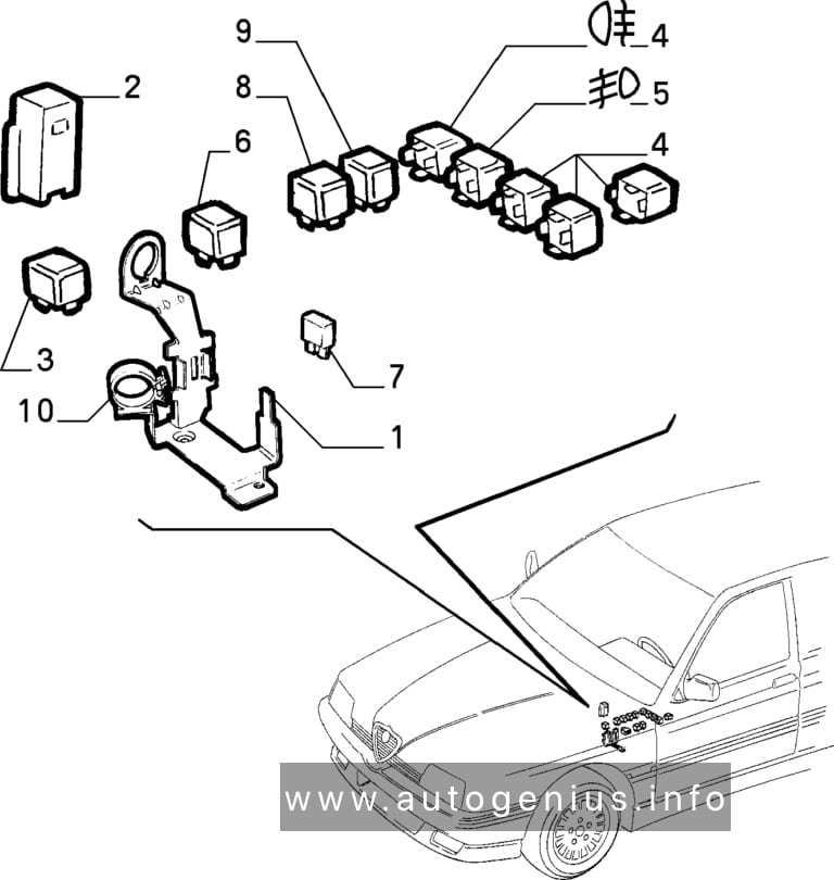
Alfa Romeo 164 is a business class car manufactured by Alfa Romeo. Produced from 1987 to 1998 in the sedan body. This material is suitable for cars produced in 1988, 1989, 1990, 1991, 1992, 1993, 1994, 1995, 1996, 1997 for finding and replacing fuses and relays on Alfa Romeo 164 cars. We will also show the fuse box diagrams and their locations, as well as the purpose of their elements.
This article covers the Chevy G30, produced from 1970 to 1996. It includes fuse box diagrams for the 1988, 1989, 1990, 1991 and 1992 models, provides details on the location of the fuse panels inside the vehicle, and explains the function and layout of each fuse.
This article covers the Chevy G20, produced from 1970 to 1996. It includes fuse box diagrams for the 1988, 1989, 1990, 1991 and 1992 models, provides details on the location of the fuse panels inside the vehicle, and explains the function and layout of each fuse.
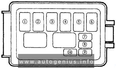
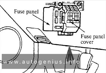
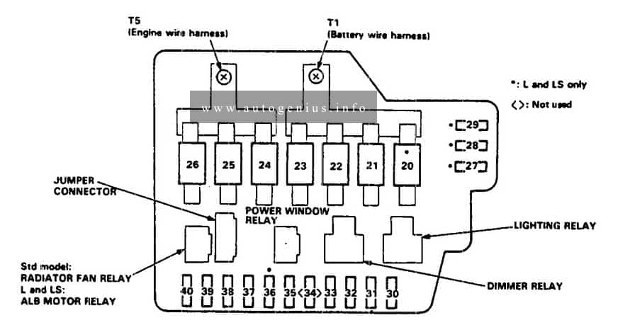
This article covers Acura Legend, produced from 1986 to 1995. It includes fuse box diagrams for the 1990 models, provides details on the location of the fuse panels inside the vehicle, and explains the function and layout of each fuse.
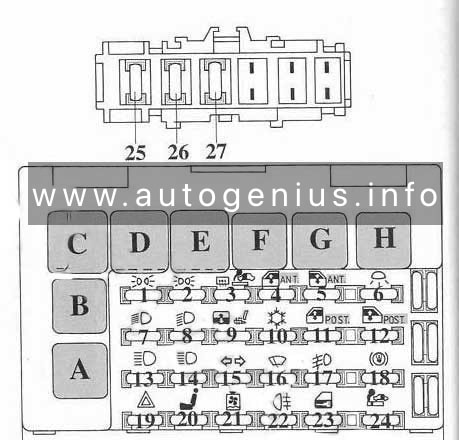
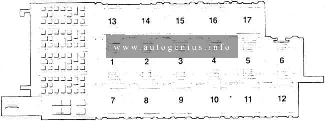
Assignment of the fuses in the passenger compartment
Fuse number
A
Circuit protected
1
7,5
Power antenna; integrated control unit; radio; climate control; clock; information center control unit
2
20
Power windows (right rear)
3
20
Power windows (right front)
4
20
Power windows (left rear)
5
7,5
Backup lights; integrated.control unit; shift position indicator; clock; gauges: indicators; safety indicator; Information center control unit; turn signal and hazard lights; SRS; shift position, console switch
6
20
Sunroof; wiper/washer motors
7
20
Power door lock control unit; trunk release
8
20
Trailer connector; lights: trunk, ignition key switch, footwall, interior, map, door courtesy, door key; cigarette lighter and illumination
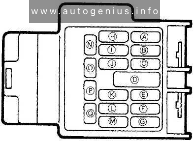
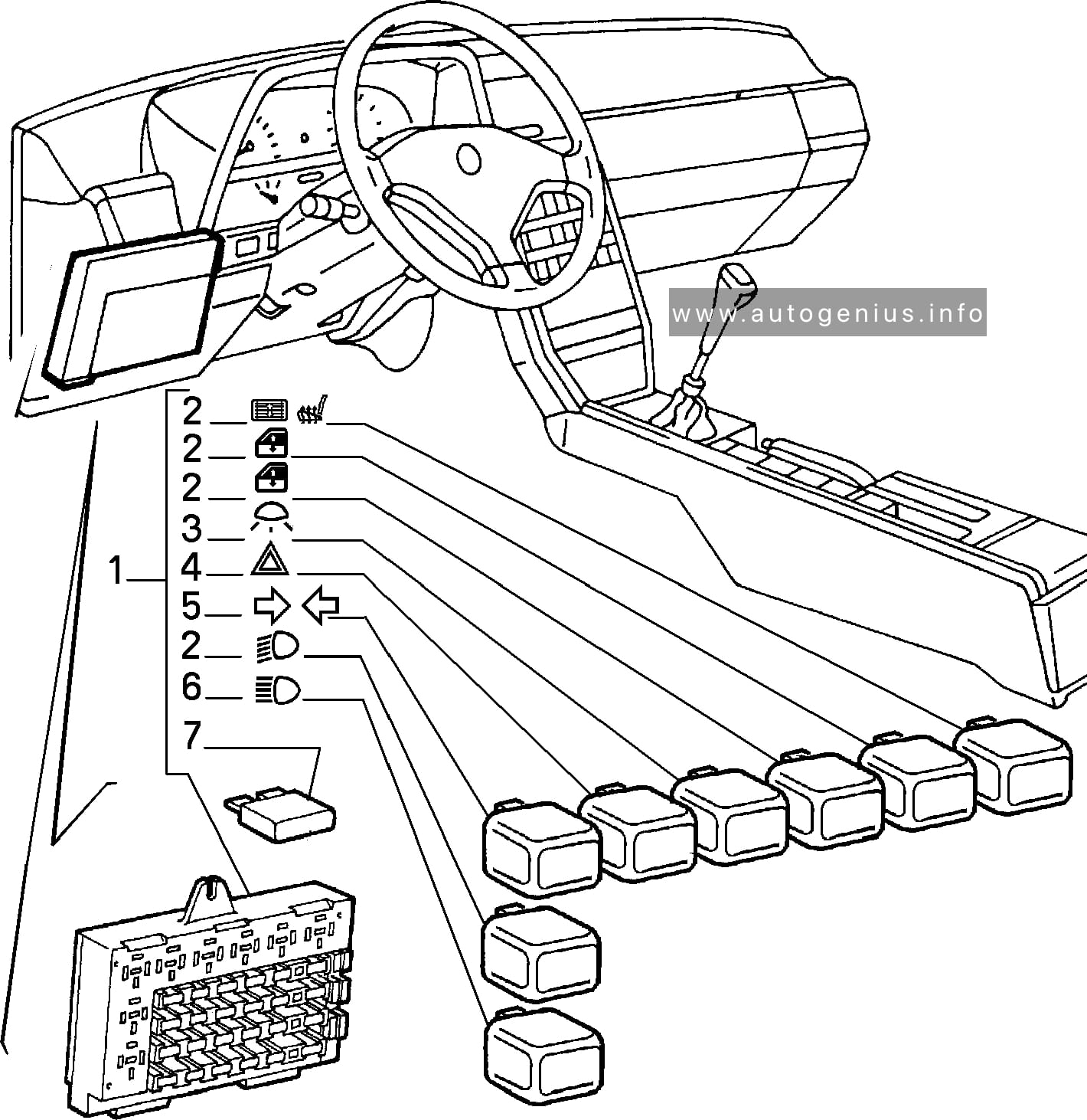
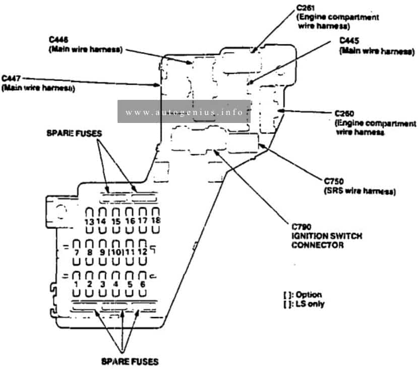
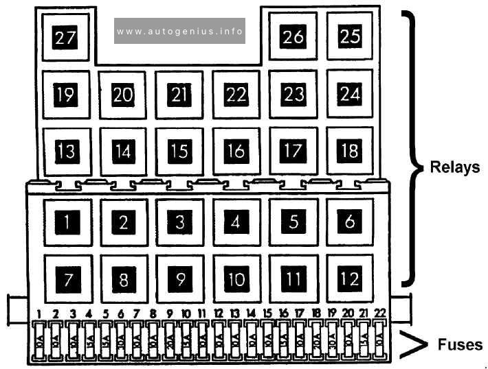
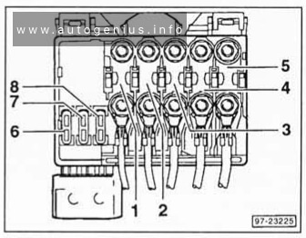
Eagle Talon (1G; 1990) – fuse and relay box diagram
Year of production: 1990
This article covers the first-generation Eagle Talon produced from 1989 to 1998. It includes fuse box diagrams for the 1990 models, provides details on the location of the fuse panels inside the vehicle, and explains the function and layout of each fuse.
Fuse box diagram
Eagel Talon (1G; 1990) – fuse and relay box diagram
Assignment of the fuses in the fuse box
Power supply circuit
No.
A
Load circuit
Battery
1
10
Automatic seatbelt control unit, key reminder switch, passing control relay, seatbelt warning buzzer, utillight relay
Ignition switch
IG2
2
—
—
3
10
Air conditioner contlol unit, air conditioner switch, defogger timer, heater relay, power window relay
ACC
4
10
Radio
5
15
Cigarette lighter, remote controlled mirror
Battery
6
15
Door lock relay, door lock control unit
Ignition switch
IG2
7
10
4-speed automatic transaxle control unit, auto-cruise control unit <A/T>, combination meter
8
—
—
ACC
9
15
Intermittent wiper relay, wiper motor, washer motor
10
10
Headlight relay, horn
IG1
11
10
Auto-cruise control unit, auto-cruise control actuator automatic seatbelt contyrol unit, combination meter
12
10
Tum-signal and hazard flasher unit
Battery
13
—
—
14
—
—
15
—
—
16
30
Blower motor
17
15
Stop light
Ignition switch
IG1
18
10
Back-UP light < M/T>, dome light relay
Battery
19
10
4-speed automatic transaxle control unit, dome light, door-ajar warning light, foot light, ignition key illumination light, luggage compartment light, MPI control unit, radio
Eagel Talon (1G; 1990) – fuse and relay box diagram
WARNING: Terminal and harness assignments for individual connectors will vary depending on vehicle equipment level, model, and market.
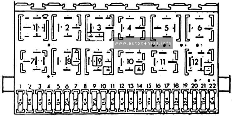
Audi 200 (C3; 1983 – 1991) – fuse and relay box diagram
Year of production: 1983, 1984, 1985, 1986, 1987, 1988, 1989, 1990, 1991
This article covers the second-generation Audi 200 (C3), produced from 1983 to 1991. It includes fuse box diagrams for the 1983, 1984, 1985, 1986, 1987, 1988, 1989, 1990 and 1991 models, provides details on the location of the fuse panels inside the vehicle, and explains the function and layout of each fuse.
Fuses box diagram
Audi 200 (C3; 1983 – 1991) – fuse and relay box diagram
Audi 100 (C3; 1983 – 1991) – fuse and relay box diagram
Year of production: 1983, 1984, 1985, 1986, 1987, 1988, 1989, 1990, 1991
This article covers the second-generation Audi 100 (c3), produced from 1983 to 1991. It includes fuse box diagrams for the 1983, 1984, 1985, 1986, 1987, 1988, 1989, 1990 and 1991 models, provides details on the location of the fuse panels inside the vehicle, and explains the function and layout of each fuse.
Fuses box diagram
Audi 100 (C3; 1983 – 1991) – fuse and relay box diagram
Year of production: 1990, 1991, 1992, 1993, 1994, 1995, 1996, 1997, 1998, 1999, 2000, 2001, 2002, 2003
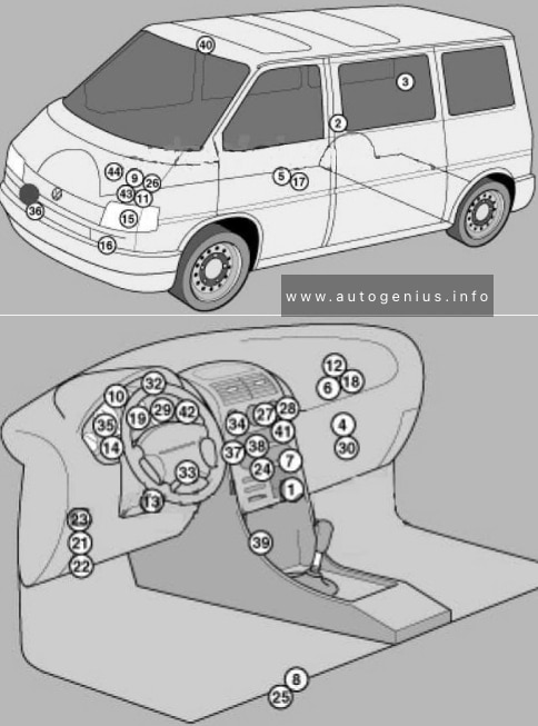
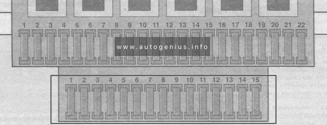
Volkswagen Transporter T4 – represents the 4th generation of the legendary Transporter series. This model was produced in 1990, 1991, 1992, 1993, 1994, 1995, 1996, 1997, 1998, 1999, 2000, 2001, 2002 and 2003 with diesel and gasoline engines with different wheelbases: short and long, and with different roof height. Also on the T4, Volkswagen continued its lineup of luxury Caravelle, California and Multivan models. In this article, we will show the location of all electronic control sides and a detailed designation of the purpose of fuses and relays Volkswagen T4 with box diagrams in which they are located.
Air conditioning control unit 1 – with automatic temperature control – in the heater control panel, front
2
Air conditioning control unit 2 – with automatic temperature control – in the heater control panel, rear – central pillar
3
Evaporator Fan Control Unit (A / C) – With Rear A / C – Behind Right Rear Trim Panel
4
Air conditioning / heater fan motor control unit 1 – with automatic temperature control – front – fan unit
5
Air conditioning / heater blower motor control unit 2- with automatic temperature control – rear- bottom of the body, in the center
6
Aerial amplifier – behind the dash, passenger side
7
Alternator resistor – near additional relays – CV / AUF, with alternator 150A / automatic transmission / automatic temperature control – behind the central part of the dashboard
8
Additional battery – under the driver’s seat
9
Accumulator battery
10
Central locking signal control unit – behind the dashboard
11
Cruise control unit (with throttle motor) – cruise control is controlled by the ECM
12
Electronic cruise control module (without throttle motor) – behind dash, passenger side
13
Diagnostic connector (DLC) – instrument panel, driver’s side
14
Diagnostic unit – 05/99 (except for AAC / ABL / AET / AES / AJA) – in the instrument cluster
15
Cooling Fan Motor Relay – Behind Left Headlight
16
Cooling Fan Motor 1/2 Resistor – Behind Left Headlight
17
Coolant heater control unit (with additional coolant heater – D3W / B4W / D4W) – in the heater – underbody, in the center
18
Coolant heater control unit (with optional coolant heater – B7W / D7W) – behind the dash, passenger side
19
Engine oil pressure warning buzzer – in instrument cluster control unit
Windshield wiper / washer, heaters for windshield washer nozzles (05/01)
6
30
Air conditioning system, heater fan motor
7
10
Front right side / rear right side lamps
8
10
Lamps front left / rear left
9
20
Heated rear window, heated outside mirror
10
15
Fog lights
11
10
Left headlamp-high beam
12
10
RH headlamp-high beam
13
10
Sound signal
14
10
ABS system (with ESP), automatic transmission control system, additional equipment, central locking, cruise control system, power windows, power rear-view mirrors on the doors, reverse light (s)
Heater blower motor relay – automatic temperature control
5
(152)
Heater radiator coolant valve relay (rear heater)
6
(38)
Air intake changeover actuator relay (A / C / heater)
7
(53)
Alternator relay (AES, with 150A alternator)
8
(53)
Alternator relay (ACV / AUF, with alternator 150A / automatic / automatic temperature control)
9
(175)
Start inhibit switch relay / reversing lamp relay
10
(87)
Wheel hub connection control unit
Another unit can be located under the driver’s seat. The following items may be located there: (214/426) Relay for additional battery, (403) Relay for additional heater, (30A) Additional liquid heating system, (5A) Sockets , etc.
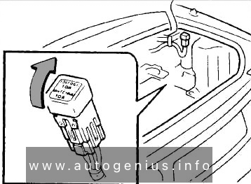
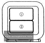
Engine compartment
Fuse box location
This unit is located on the cover in front of the battery.