Toyota Previa First Generation mk1 (XR10, XR20; 1990–1999) – fuse box diagram
Year of production: 1990, 1991, 1992, 1993, 1994, 1995, 1996, 1997, 1998, 1999
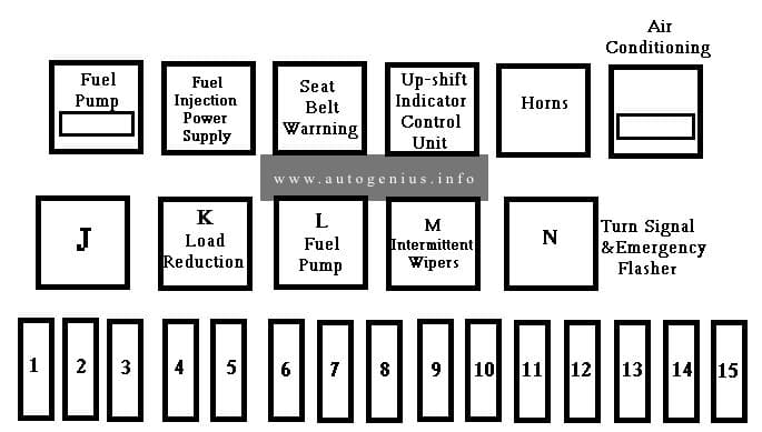
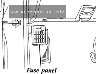
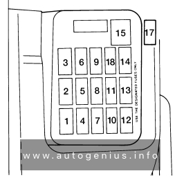
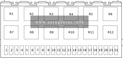
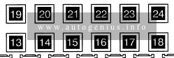
Instrument panel
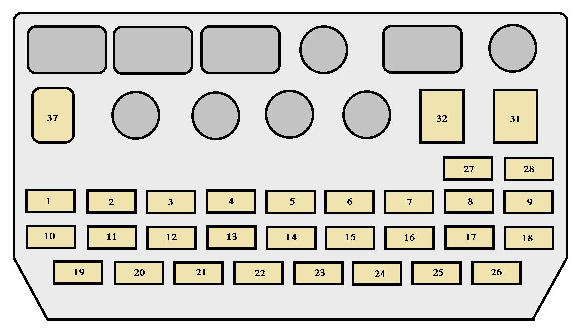
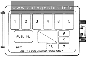
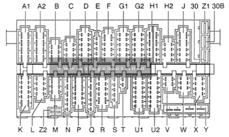
Front compartment
Fuses (type A)
| Fuse | Ampere rating [A} | Circuit | |
| 1 | ST | 7,5 | Starter system |
| 2 | IGN | 7,5 | Charging system, discharge warning light, emission control system, multiport fuel injection system/sequential multiport fuel injection system, SRS airbag system |
| 3 | OBD | 7,5 | On-board diagnosis system |
| 4 | FOG | 20 | Front fog lights |
| 5 | T/M ACC | 7,5 | Automatic transmission shift indicator |
| 6 | TAIL | 15 | Tail lights, parking lights, side marker lights, license plate lights, instrument panel lights |
| 7 | HAZ-HORN | 15 | Emergency flashers, horns, turn signal lights |
| 8 | HEAD (LH) | 15 (USA) | Left-hand headlight |
| HEAD (LH-L WR) |
10 (Canada) | ||
| 9 | HEAD (RH) | 15 (USA) | Right-hand headlight |
| HEAD (RH-L WR) |
10 (Canada) | ||
| 10 | ENGINE | 7,5 | Charging system, emission control system |
| 11 | RADIO | 7,5 | Radio, cassette tape player, Compact Disc player |
| 12 | ST-A | 7,5 | Starter system |
| 13 | STOP | 20 | Stop lights, anti-lock brake system |
| 14 | DOME | 15 | Interior lights, luggage compartment light, clock, open door warning light, radio, cassette tape player, Compact Disc player |
| 15 | DEFOG | 15 | Rear window defogger |
| 16 | ECU-B | 15 | Anti-lock brake system, electronically controlled automatic transmission system |
| 17 | CIG | 15 | Cigarette lighter, digital clock display, power rear view mirrors, theft deterrent system, SRS airbag system, automatic transmission shift lock system |
| 18 | EFI | 15 | Multiport fuel injection system/sequential multiport fuel injection system |
| 19 | TURN | 7,5 | Turn signal lights |
| 20 | GAUGE | 10 | Gauges and meters, service reminder indicators and warning buzzers (except discharge and open door warning lights), back-up lights, automatic transmission overdrive system, rear window defogger, electric rear sun roof, power windows, power door lock system |
| 21 | FR-WIPER | 30 | Windshield wipers and washer |
| 22 | ENGINE OIL | 15 | Engine oil autofeed system |
| 23 | RR-WIPER | 15 | Rear window wiper and washer |
| 24 | A/C | 15 | Air conditioning cooling system, cool box |
| 25 | ECU-IG | 15 | Cruise control system, electronically controlled automatic transmission system, anti-lock brake system, theft deterrent system |
| 26 | FR-W ASHER | 10 | Windshield washer motor |
| 27 | HEAD (LH-UPR) | 10 | Left-hand headlight (Canada only) |
| 28 | HEAD (RH-UPR) | 10 | Right-hand headlight (Canada only) |
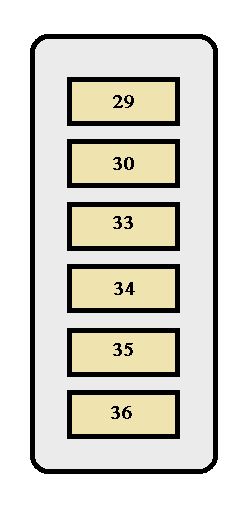
| 29 | ALT-S | 7,5 | Charging system |
| 30 | AM2 | 20 | Charging system, discharge warning light, emission control system, multiport fuel injection system/ sequential multiport fuel injection system |
Fuses (type B)
| Fuse | Ampere rating [A] | Circuit | |
| 31 | DOOR | 30 | Power door lock system, theft deterrent system |
| 32 | POWER | 30 | Electric rear sun roof, power windows |
Fuses (type C)
| Fuse | Ampere rating [A] | Circuit | |
| 33 | ABS | 60 | Anti-lock brake system |
| 34 | ALT | 100 | “ABS”, “AM1”, “STOP”, “DEFOG”, “FOG”, “ECU-B”, “TAIL”, “A/C” and “RR A/C” fuses, and “FR-HTR” circuit breaker |
| 35 | AM1 | 50 | “ENGINE”, “GAUGE”, “TURN”, “FR-WIPER”, “ECU-IG”, “A/C”, “RADIO”, “CIG”, “ST”, “POWER” and DOOR” fuses |
| 36 | MAIN | 50 | “HAZ-HORN”, “DOME”, “HEAD (LH)”, “HEAD (RH)” and “EFI” fuses |
Circuit breaker
| Fuse | Ampere rating [A] | Circuit | |
| 37 | FR-HTR C/B | 40 | Air conditioning control system |
WARNING: Terminal and harness assignments for individual connectors will vary depending on vehicle equipment level, model, and market.