The Dodge Ram 1500 from 1994 to 1997 was a key model in the history of Dodge trucks, marking the debut of the second generation of the Dodge Ram series. This generation saw a radical redesign that helped revitalize Dodge’s truck sales, making the Ram one of the most iconic pickup trucks of the 1990s.
Passenger Compartment Fuse Box
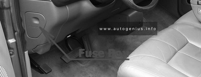
Fuse Box Location
The fuse panel is located behind the cover on the driver’s side of the instrument panel.
Ignition Off Draw, Clock Memory, Underhood Lamp, Power Mirror Switch, Time Delay Relay, Buzzer Module, Data Link Connector, Radio Choke Relay, Glove Box Lamp Switch, Radio
18
15
’94-’95: Parking Lamps
15
’96-’97: Headlamp Switch, Radio, Overhead Console, Fog Lamp Relay
Chrysler Neon (1994 – 1999) – fuse and relay box diagram
Year of production: 1994, 1995, 1996, 1997, 1998, 1999
The Chrysler Neon, also known as the Dodge Neon in some markets, was a compact car produced by Chrysler Corporation from 1994 to 2005. It was initially marketed under both the Dodge and Plymouth brands in North America and as the Chrysler Neon in international markets.
First Generation (1994–1999), Second Generation (2000–2005), Dodge Neon SRT-4 (2003–2005)
Passenger Compartment Fuse Box
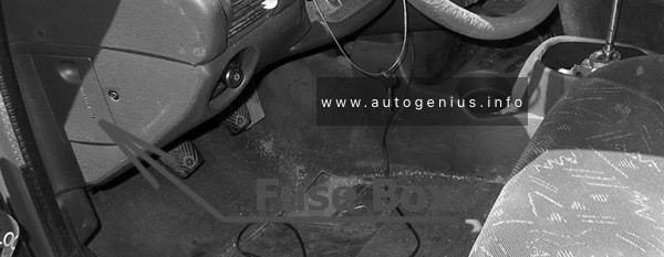
Fuse box location
The fuse panel is located behind the cover on the driver’s side of the dashboard.
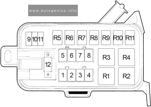
Chrysler Neon (1994 – 1999) – fuse and relay location – passenger compartment
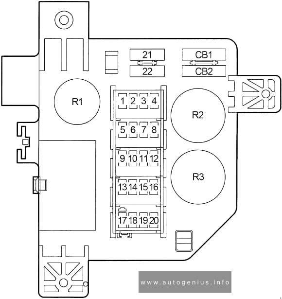
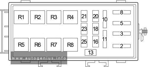
Fuse box Diagram
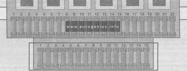
Chrysler Neon (1994 – 1999) – fuse and relay diagram – passenger compartment
Assignment of fuses in the passenger compartment
No.
A
Circuit Protected
1
15
Cigar Lighter/Power Outlet
2
15
Headlamp Switch (Park Lamp, Tail Lamp, License Lamp, Radio, Front Fog Lamp Switch, Remote Keyless Entry Module (’98-’99))
3
20
Door Lock Switch, Remote Keyless Entry Module (’98-’99), Immobilizer (’98-’99)
Dome Lamp, Trunk Lamp, Underhood Lamp, Instrument Cluster, Radio, Glove Box Lamp, Map/Reading Lamp, Visor/Vanity Lamp, Power Mirror Switch, High Speed Warning Module (’98-’99), Time Delay Relay (’98-’99), Time Out Relay (’98-’99)
16
20
Fog Lamp Relay, Rear Fog Lamp Switch
18
10
’95-’97: Air Conditioner Compressor Clutch Relay
20
’98-’99: Air Conditioner Compressor Clutch Relay, ABS
20
10
Turn Signal/Hazard
21
20
Fuel Pump Relay, Auto Shut Down Relay (Fuel Injectors, Ignition Coil Pack, Powertrain Control Module, Generator, Data Link Connector, Oxygen Sensors, Capacitor, Noise Suppressor)
23
15
Horn Relay
25
15
Stop Lamp Switch
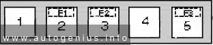
Relay
R1
–
R2
Fuel Pump
R3
Auto Shut Down
R4
Horn
R5
Fog Lamp
R6
ABS Warning Lamp
R7
Air Conditioner Compressor Clutch
R8
Starter
WARNING: Terminal and harness assignments for individual connectors will vary depending on vehicle equipment level, model, and market.
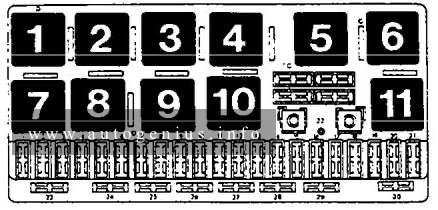
This article covers the second-generation Audi 100 (C4), produced from 1990 to 1994. It includes fuse box diagrams for the 1992, 1993 and 1994 models, provides details on the location of the fuse panels inside the vehicle, and explains the function and layout of each fuse.
Passenger compartment
Fuse box diagram
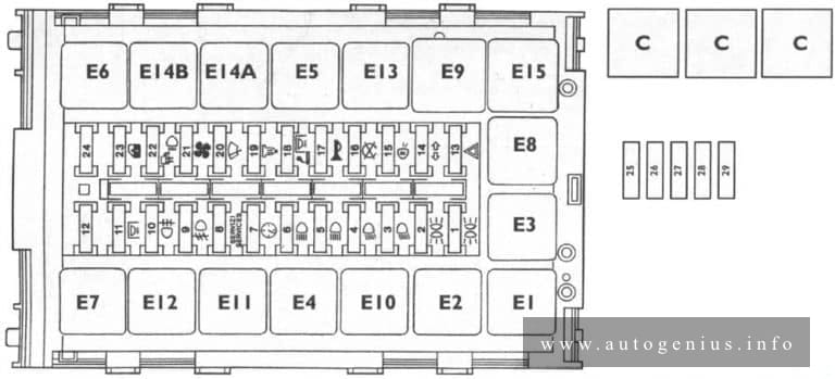
Audi 100 (C4; 1992 – 1994) – fuse and relay box diagram – passenger compartment (instrument panel)
Assignment of the fuses in the passenger compartment (instrument panel)
№
A
Description
1
15
Rear fog lights
2
15
Emergency flash switch, anti-theft system (USA only)
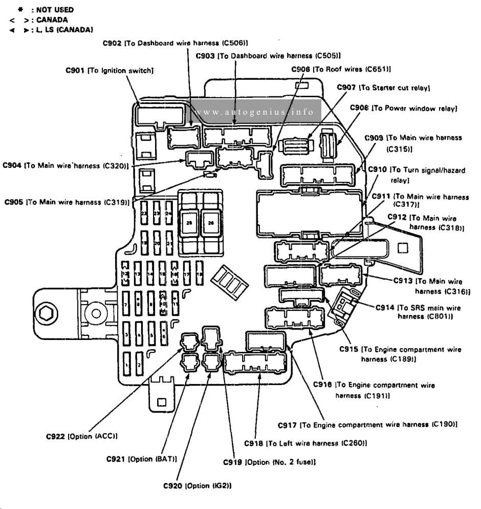
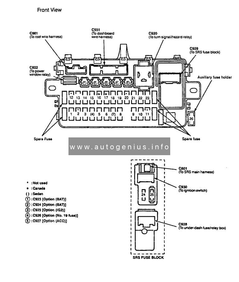
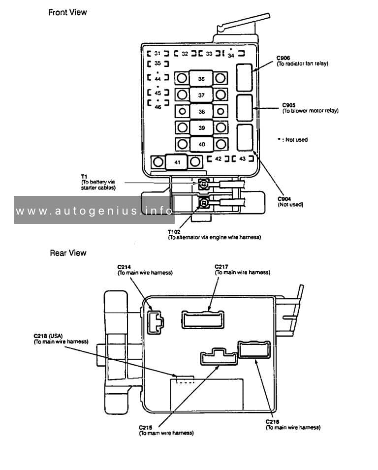
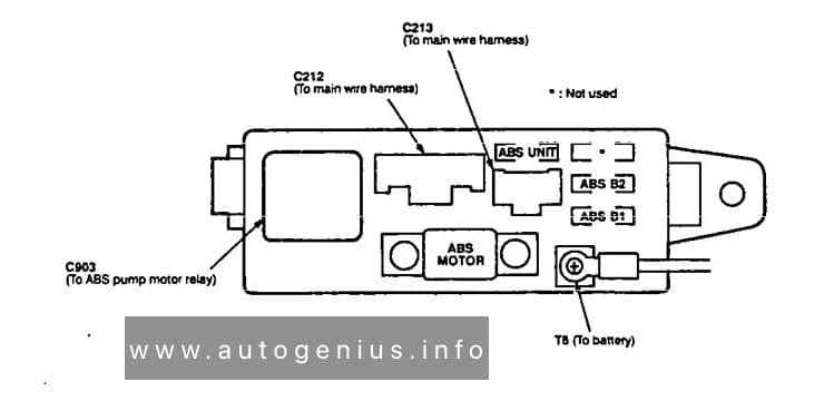
This article covers Acura Legend, produced from 1986 to 1995. It includes fuse box diagrams for the 1994 and 1995 models, provides details on the location of the fuse panels inside the vehicle, and explains the function and layout of each fuse.
Passenger compartment
Fuse box location
Under-dash fuse box is located behind left kick panel
Assignment of the fuses in the passenger compartment
Number
A
Component or Citcuit Protected
1
—
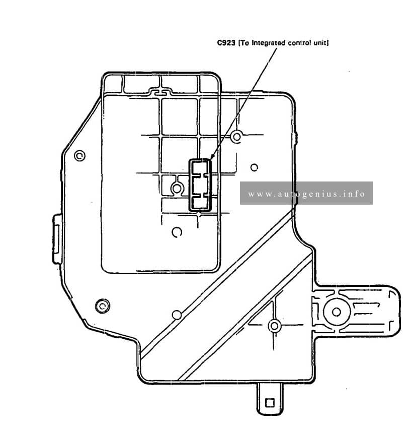
Option connector: C921
2
—
Option connector: C919
3
15
ASS pump motor relay, ABS control unit, ABS front and rear failsale relays, ABS inspection connector, A/C compressor clutch, A/C compressor clutch relay, Fan control unit, Radiator fan relay, Rear window defogger relay, Rear window defogger indicator fight, (option C920)
Seat belt presenter, Power door closer control unit
9
15
Cigarette lighter
10
15
Heated seat (seat backs, cushions. and switches)
11
20
A/C compressor clutch relay
12
7,5
Daytime running lights control unit
13
7,5
Integrated control unit, Clock, Gauges, Back-up lights, Turn signal/hazard relay, Shift lock solenoid, Seat belt tension control
14
7,5
Powertrein or engine control module, PGM-FI main relay, Gauge assembly (bulb check circuit)
15
7,5
Powertraln or engine control module, Radiator fan control module, Security control unit, Driving position memory system (OPMS), Charging system
16
20
Daytime running lights control unit
17
20
Power window control unit
18
20
Passenger’s power window motor
19
7,5
Climate control unit, Heater control panel, Seat heater relay, Healed minors, Recirculation control motor, Blower motor relay, Blower motor high relay, Power mirror actuators, Mode control motor (manual A/C)
20
7,5
Cruise control unit. Radiator fan control module, Security control unit, Driving position memory system (DPMS)
21
—
—
22
20
PGM·FI, SRS unit, Charging system, Traction control system (TCS), Vehicle speed sensor (VSS)
Hom relay, Left and right horns, Key Interlock solenoid, Security Indicator, ABS control unit, Cruise control unit, Powetrain or engine control module, Brake lights, Trailer fighting connector
40
15
Tum signal/hazard relay, Hazard warning lights
41
15
ABS control unit (B1)
42
15
ABS control unit (B2), TCS control unit
43
15
ABS control unit (B3)
44
20
Power door lock, control unit, Trunk opener solenoid
45
20
Right headnght. Daytime running lights control unit (Canada)
46
20
Left headlight, High beam indicator light, Daytime running lights control(Canada)
47
20
Radiator fan motor
48
10
Left taillight, Trailer lighting connector
49
15
Front parldng lights, Vanity mirror lights, License plate lights, Right taillights, Integrated control unit, Rear spot lights, Gauge lights, Stereo radio/cassette player, Courtesy light controller (LS and GS), Dash lights brightness control unit, Dash lights
50
20
Condenser fan motor
51
30
Moonroof motor
52
30
Front passenger’s power seat motors (slide-recline)
53
15
Traction control system (TCS)
54
20
Amplifier
55
30
Power seat control unit
56
7,5
Climate control unit, Clock, Stereo radio/cassette player, Power antenna motor, car telephone system, Integrated control unit
57
15
Front courtesy lights, Rear courtesy lights, Trunk light, Footwell lights, Ignition key light, Front and rear celing lights, Trailer lighting connector, Ceiling light relay, Front spot lights
58
30
Steering oolurnn control unit
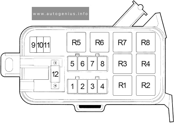
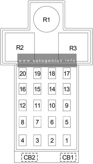
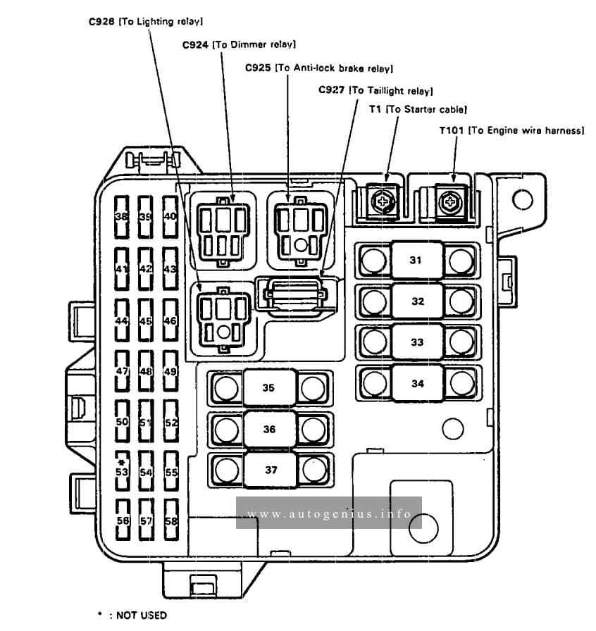
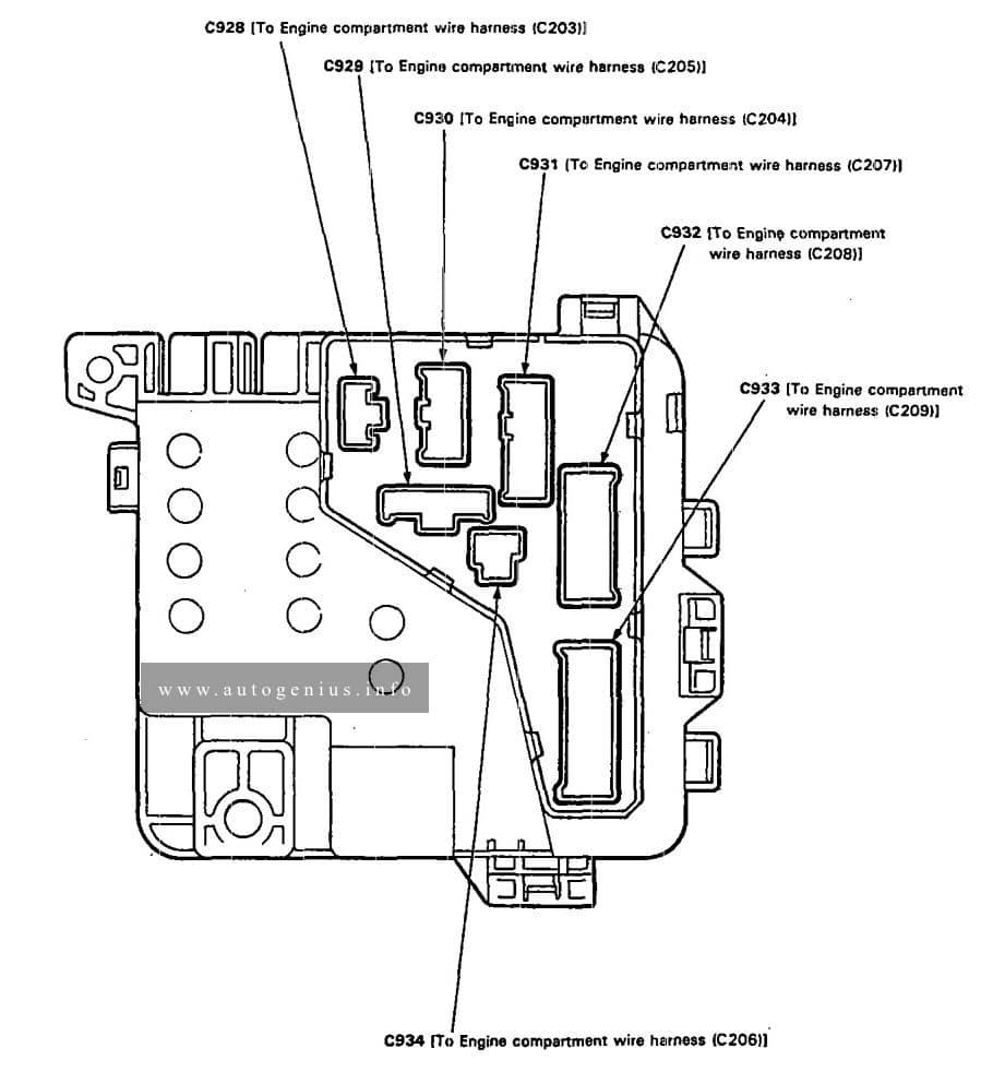
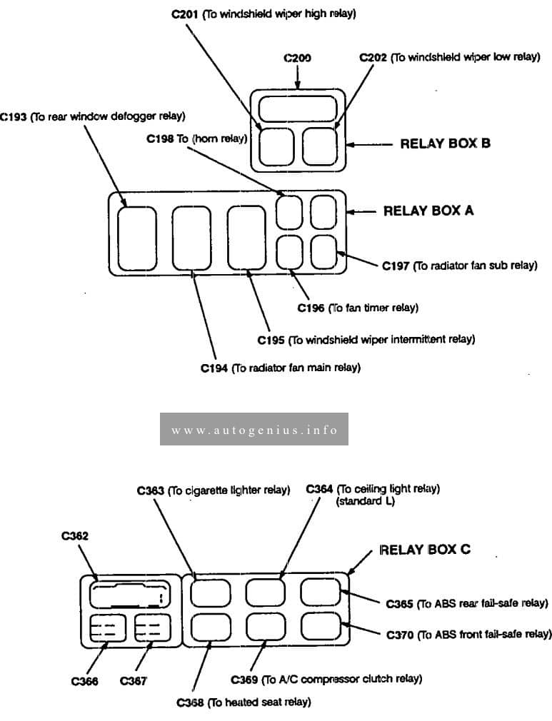
Fuse box diagram
Acura Legend (1994 – 1995)- fuse and relay box diagram
WARNING: Terminal and harness assignments for individual connectors will vary depending on vehicle equipment level, model, and market.
This article covers the pre-facelift third-generation Acura Integra, produced from 1994 to 1997. It includes fuse box diagrams for the 1994, 1995, 1996, and 1997 models, provides information on the location of the fuse panels within the vehicle, and details the function of each fuse (fuse layout).
Passenger Compartment Fuse Box
Fuse Box Location
The interior fuse box is underneath the dashboard on the driver’s side.
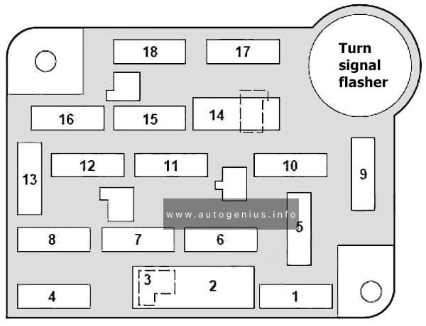
Ford F-150 (1992 – 1997) – fuse and relay box diagram
Year of production: 1992, 1993, 1993, 1994, 1995, 1996, 1997
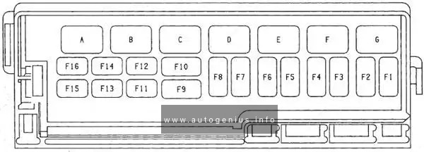
This article focuses on the ninth-generation Ford F-Series, produced from 1992 to 1997. It provides fuse box diagrams for the 1992, 1993, 1994, 1995, 1996, and 1997 Ford F-150, F-250, and F-350 models, along with information on the locations of the fuse panels within the vehicle and the assignment of each fuse and relay (fuse layout).
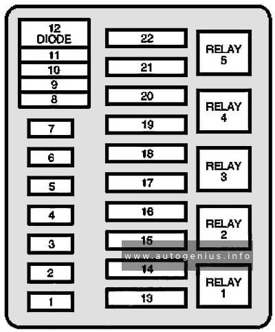
Passenger Compartment Fuse Panel
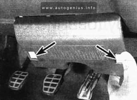
Fuse box location
The fuse panel is located behind the cover to the left of the steering wheel. Remove the cover from the lower edge of the instrument panel by pulling on handle to disengage the fasteners.
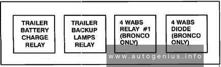
Fuse box diagram
Ford F-150 – fuse and relay box diagram – passenger compartment
Year of production: 19991, 1992, 1993, 1994, 1995, 1996, 1997, 1998
The 3rd generation Volkswagen Golf compact car was produced in 1991, 1992, 1993, 1994, 1995, 1996, 1997, 1998, 1999, 2000, 2001 and 2002 with gasoline and diesel engines. Delivered worldwide in various body styles: convertible, sedan, station wagon and hatchback. In this article you will find a designation of the fuse and relay boxes diagram of the 3rd generation Volkswagen Golf.
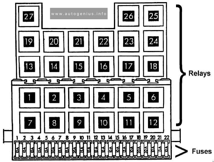
Passenger compartment
Fuse box location
It is located at the bottom of the dashboard on the driver’s side, behind the protective cover. To remove it, press the buttons – latches.
Year of production: 1990, 1991, 1992, 1993, 1994, 1995, 1996, 1997, 1998, 1999, 2000, 2001, 2002, 2003
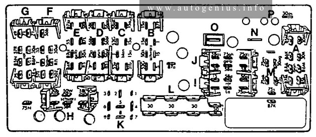
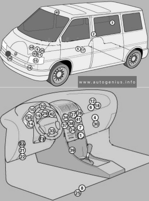
Volkswagen Transporter T4 – represents the 4th generation of the legendary Transporter series. This model was produced in 1990, 1991, 1992, 1993, 1994, 1995, 1996, 1997, 1998, 1999, 2000, 2001, 2002 and 2003 with diesel and gasoline engines with different wheelbases: short and long, and with different roof height. Also on the T4, Volkswagen continued its lineup of luxury Caravelle, California and Multivan models. In this article, we will show the location of all electronic control sides and a detailed designation of the purpose of fuses and relays Volkswagen T4 with box diagrams in which they are located.
Air conditioning control unit 1 – with automatic temperature control – in the heater control panel, front
2
Air conditioning control unit 2 – with automatic temperature control – in the heater control panel, rear – central pillar
3
Evaporator Fan Control Unit (A / C) – With Rear A / C – Behind Right Rear Trim Panel
4
Air conditioning / heater fan motor control unit 1 – with automatic temperature control – front – fan unit
5
Air conditioning / heater blower motor control unit 2- with automatic temperature control – rear- bottom of the body, in the center
6
Aerial amplifier – behind the dash, passenger side
7
Alternator resistor – near additional relays – CV / AUF, with alternator 150A / automatic transmission / automatic temperature control – behind the central part of the dashboard
8
Additional battery – under the driver’s seat
9
Accumulator battery
10
Central locking signal control unit – behind the dashboard
11
Cruise control unit (with throttle motor) – cruise control is controlled by the ECM
12
Electronic cruise control module (without throttle motor) – behind dash, passenger side
13
Diagnostic connector (DLC) – instrument panel, driver’s side
14
Diagnostic unit – 05/99 (except for AAC / ABL / AET / AES / AJA) – in the instrument cluster
15
Cooling Fan Motor Relay – Behind Left Headlight
16
Cooling Fan Motor 1/2 Resistor – Behind Left Headlight
17
Coolant heater control unit (with additional coolant heater – D3W / B4W / D4W) – in the heater – underbody, in the center
18
Coolant heater control unit (with optional coolant heater – B7W / D7W) – behind the dash, passenger side
19
Engine oil pressure warning buzzer – in instrument cluster control unit
Windshield wiper / washer, heaters for windshield washer nozzles (05/01)
6
30
Air conditioning system, heater fan motor
7
10
Front right side / rear right side lamps
8
10
Lamps front left / rear left
9
20
Heated rear window, heated outside mirror
10
15
Fog lights
11
10
Left headlamp-high beam
12
10
RH headlamp-high beam
13
10
Sound signal
14
10
ABS system (with ESP), automatic transmission control system, additional equipment, central locking, cruise control system, power windows, power rear-view mirrors on the doors, reverse light (s)
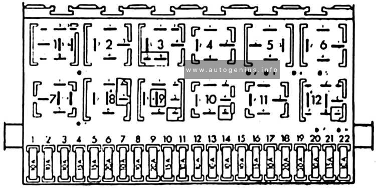
Heater blower motor relay – automatic temperature control
5
(152)
Heater radiator coolant valve relay (rear heater)
6
(38)
Air intake changeover actuator relay (A / C / heater)
7
(53)
Alternator relay (AES, with 150A alternator)
8
(53)
Alternator relay (ACV / AUF, with alternator 150A / automatic / automatic temperature control)
9
(175)
Start inhibit switch relay / reversing lamp relay
10
(87)
Wheel hub connection control unit
Another unit can be located under the driver’s seat. The following items may be located there: (214/426) Relay for additional battery, (403) Relay for additional heater, (30A) Additional liquid heating system, (5A) Sockets , etc.
Engine compartment
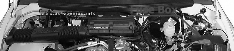
Fuse box location
This unit is located on the cover in front of the battery.
Year of production: 1989, 1990, 1991, 1992, 1993, 1994, 1995, 1996, 1997, 1998, 1999, 2000
This article covers the second-generation Iveco Daily II (2nd generation), produced from 1989 to 2000. It includes fuse box diagrams for the 1989, 1990, 1991, 1992, 1993, 1994, 1995, 1996, 1997, 1998, 1999 and 2000 models, provides details on the location of the fuse panels inside the vehicle, and explains the function and layout of each fuse.
Year of production: 1987, 1988, 1989, 1990, 1991, 1992, 1993, 1994, 1995, 1995
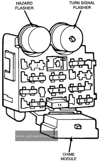
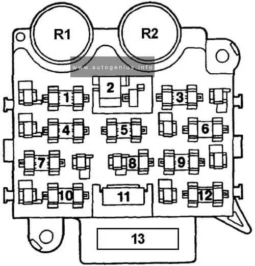
This article focuses on the first-generation Jeep Wrangler (YJ), manufactured between 1987 and 1995. It includes fuse box diagrams for the 1987–1995 models, details the locations of the fuse panels within the vehicle, and provides information on the function and layout of each fuse and relay.