Honda HR-V (1999 – 2006) – fuse and relay box diagram
Year of production: 1999, 2000, 2001, 2002, 2003, 2004, 2005, 2006
This article covers the first-generation Honda HR-V (GH), manufactured from 1999 to 2006. It includes fuse box diagrams for the Honda HR-V models from 1999 to 2006, details the locations of the fuse panels within the vehicle, and explains the function of each fuse and relay (fuse layout).
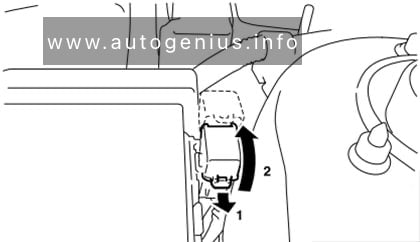
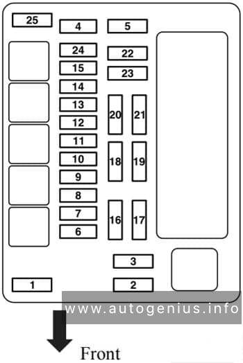
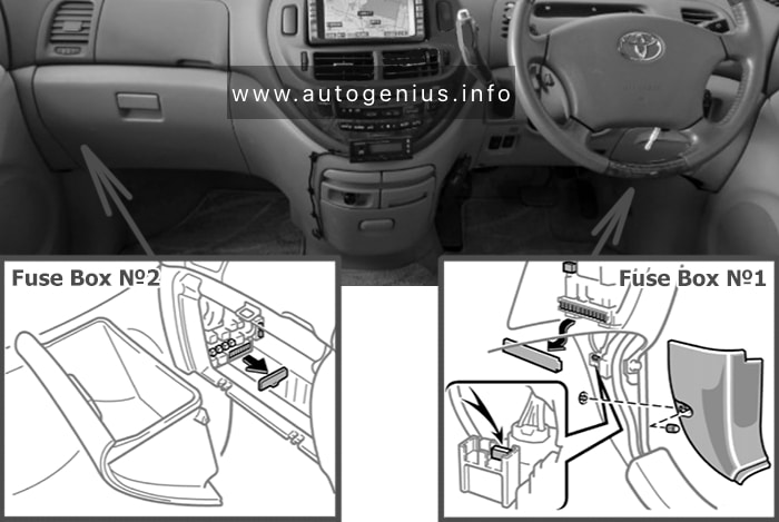
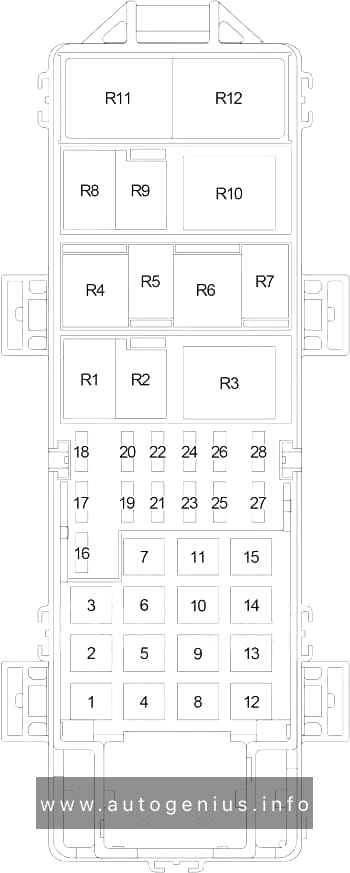
Passenger Compartment Fuse Panel
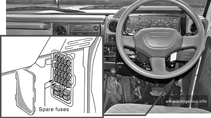
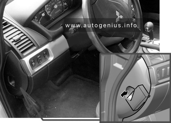
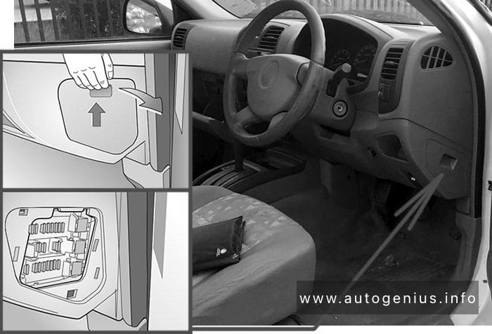
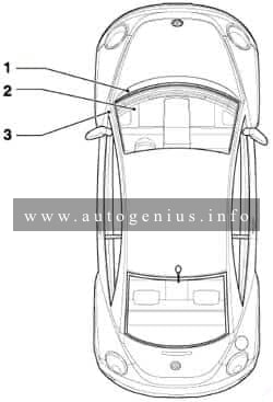
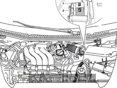
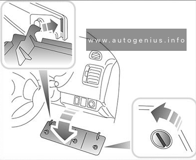
Fuse Box Location
The fuses are located under the dashboard on the driver’s side
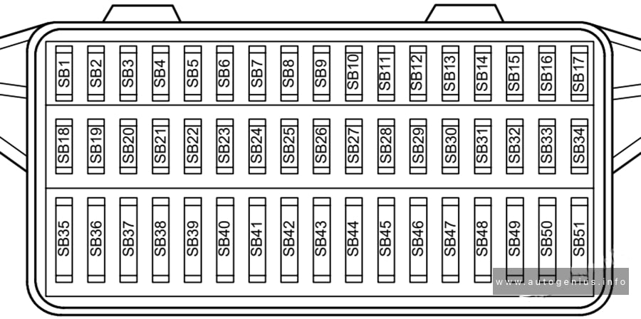
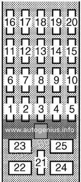
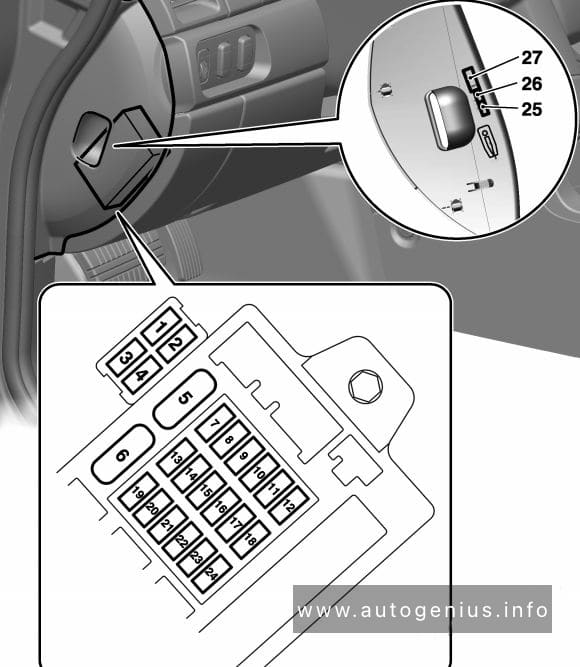
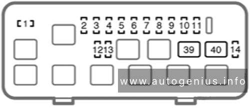
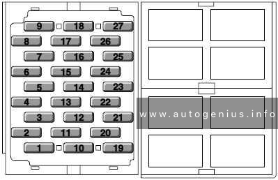
Fuse Box Diagram
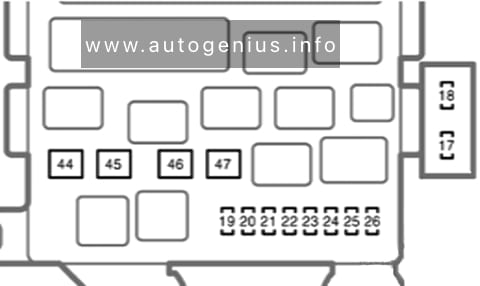
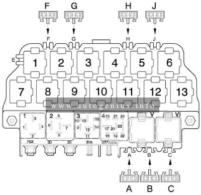
Assignment of the fuses in the instrument panel
| № | Amps | Component(s) or Circuit(s) Protected |
|---|---|---|
| 1 | 10A | SRS unit (VA) |
| 2 | 15A | SRS unit (VA) Inertia switch (KG and KE models), PGM-FI main relay (Except KG and KE models) |
| 3 | 20A | Windshield wiper motor, windshield washer motor |
| 4 | 10A | Headlight adjuster switch (KG and KE models), headlight adjuster unit (KG and KE models), rear window intermittent wiper control unit (KG and KE models), rear window washer motor, rear window wiper motor, power window master switch, power window relay |
| 5 | 10A | Integrated control unit, turn signal/hazard relay, back-up lights |
| 6 | 7.5A | Gauge Assembly, Clock, vehicle speed alarm unit (KY model), seat belt alarm unit (KY and KQ models), keyless door lock control unit, secondary HO2S (KG, KE, KN and KQ models), ELD unit (CVT), alternator, VSS, primary HO2S (KG, KE and KU models), PCM, EVAP purge control solenoid valve (KG, KY, KE and KU models) |
| 7 | 15A | Distributor |
| 8 | – | Not used |
| 9 | – | Not used |
| 10 | 15A | Rear window defogger |
| 11 | 7.5A | Blower motor relay, radiator fan relay, condenser fan relay, A/C switch, A/C compressor clutch relay, recirculation control motor, A/C thermostat, ABS modulator assembly, power mirror actuator, power mirror defogger (KG model), power mirror retract actuator (with keyless entry system), seat heater main relay (KG model) |
| 12 | – | Not used |
| 13 | 7.5A | ECM/PCM, PGM-FI main relay |
| 14 | – | Not used |
| 15 | – | Not used |
| 16 | – | Not used |
| 17 | – | Not used |
| 18 | 15A | Audio unit, cigarette lighter |
| 19 | – | Not used |
| 20 | – | Not used |
| 21 | – | Not used |
| 22 | – | Not used |
| 23 | 7.5A | Clock, seat belt alarm unit (KY and KQ models), intregated control unit, ceiling lights, immobiliser indicator light (KG, KE, KQ and KU models), cargo area light, ECM/PCM |
| 24 | 15A | Audio unit |
| 25 | 15A | Keyless / power door lock control unit |
| 26 | – | Not used |
| 27 | – | Not used |
| 28 | – | Not used |
| S | Spare fuses | |
| R1 | Power window relay | |
| R2 | Taillight relay | |
| R3 | Seat heater main relay (KG model) Shift lock relay (KQ and KU models with CVT) |
|
| R4 | Turn signal/hazard relay |
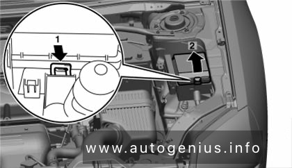
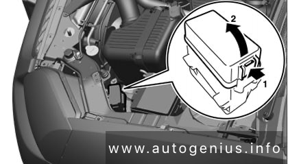
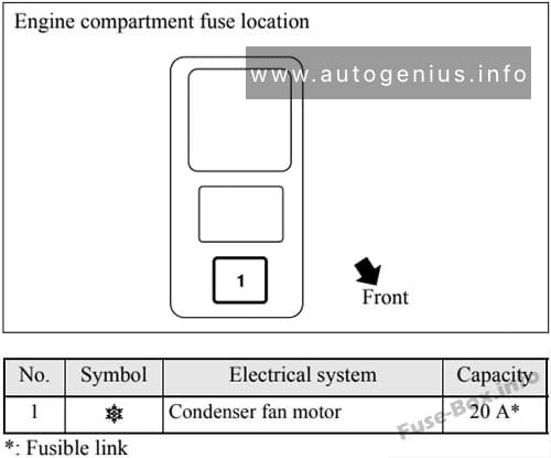
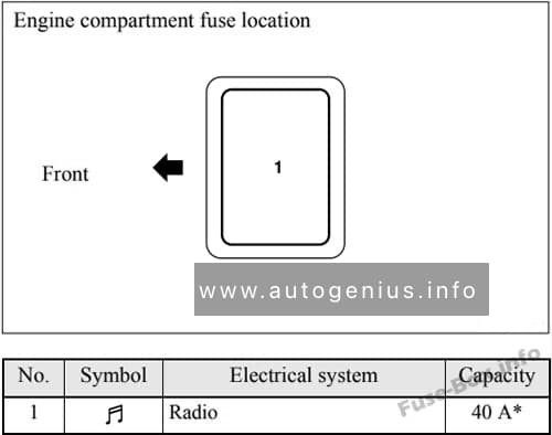
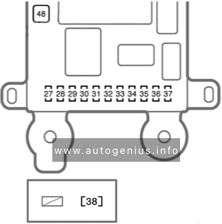
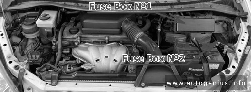
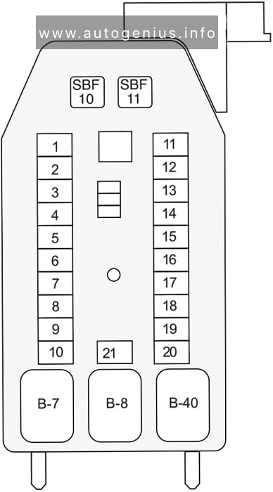
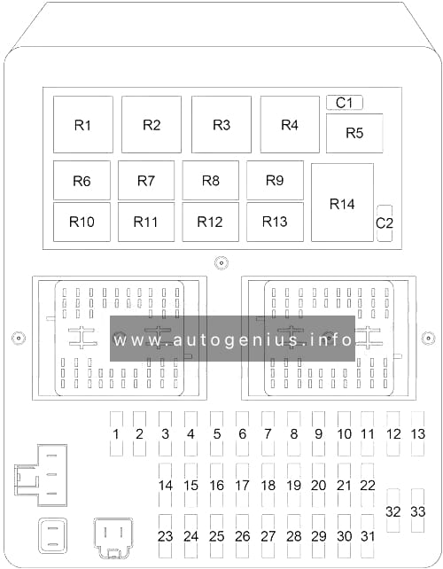
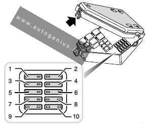
Engine Compartment Fuse Box
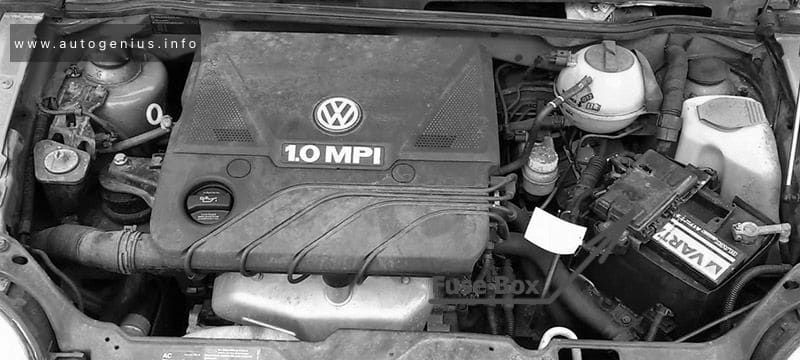
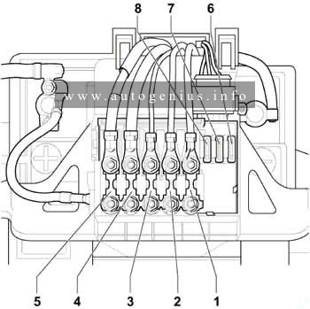
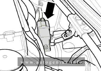
Fuse Box Location
The fuse box is located near the battery.
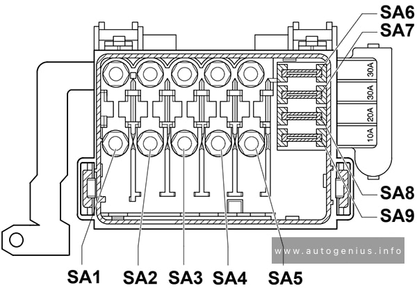
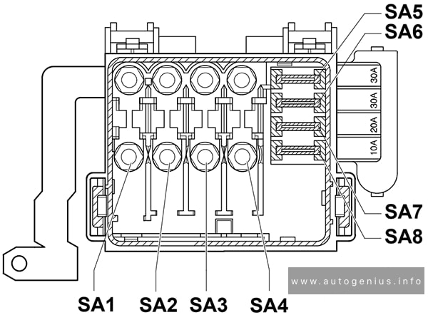
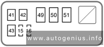
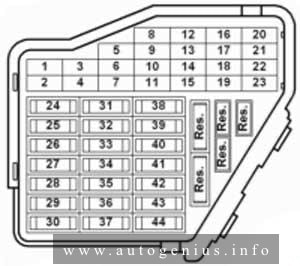
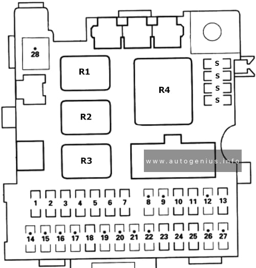
Fuse Box Diagram
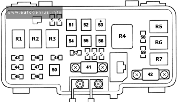
Assignment of the fuses in the engine compartment
| № | Amps | Component(s) or Circuit(s) Protected |
|---|---|---|
| 41 | 80A | Battery, power distribution |
| 42 | 50A | Ignition switch (BAT) |
| 43 | 20A | Right headlight, High beam indicator light |
| 44 | 7.5A | Rear fog light control unit (KG, KE models) |
| 45 | 20A | Left headlight |
| 46 | 7.5A / 10A | Taillight relay, clock, switch lights, taillights, licence plate lights, integrated control unit, gauge lights, audio unit light, beverage holder light, heater control panel light, front parking lights, dashlights brightness controller (KQ model), option connector C |
| 47 | 10A / 15A | Brake lights, key interlock solenoid (KQ, KU models), ABS modulator assembly ECM/PCM |
| 48 | 20A | ABS modulator assembly |
| 49 | 10A / 15A | Turn signal/hazard lights, hazard warning light (KG and KE models) |
| 50 | 40A | ABS modulator assembly |
| 51 | 20A | Power window relay, passenger’s window motor |
| 52 | 20A | Power window master switch, driver’s window motor |
| 53 | – | Not used |
| 54 | 30A | № 23, 24 and 25 fuses (in under-dash fuse/relay box), option connector B |
| 55 | 20A | Seat heaters (KG model) |
| 56 | 40A | Blower motor |
| 57 | 20A | Radiator fan motor |
| 58 | 20A | Condenser fan motor A/C compressor clutch |
| 59 | 15A | PGM-FI main relay, data link connector |
| S | Spare fuses | |
| R1 | Headlight relay 1 | |
| R2 | Headlight relay 2 | |
| R3 | Horn relay | |
| R4 | Blower motor relay | |
| R5 | Condenser fan relay | |
| R6 | Radiator fan relay | |
| R7 | A/C compressor clutch relay |
WARNING: Terminal and harness assignments for individual connectors will vary depending on vehicle equipment level, model, and market.