Volkswagen Lupo (2000 – 2006) – fuse box diagram
Year of production: 2000, 2001, 2002, 2003, 2004,2005, 2006
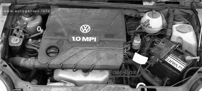
Volkswagen Lupo was produced mainly in the body of a 3-door hatchback in 1998, 1999, 2000, 2001, 2002, 2003, 2004, 2005 and 2006. Positioned as a city car with low fuel consumption. In this material you will find a designation of the purpose of fuses and relays in Volkswagen Lupo, diagrams of the boxes in which they are located.
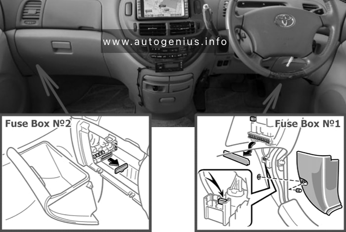
Passenger compartment
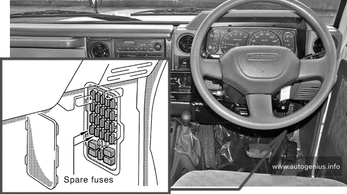
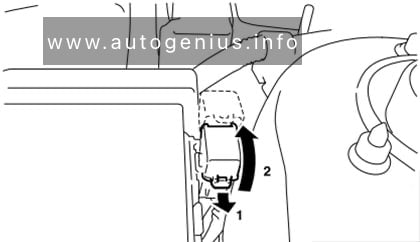
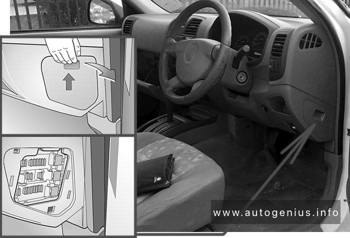
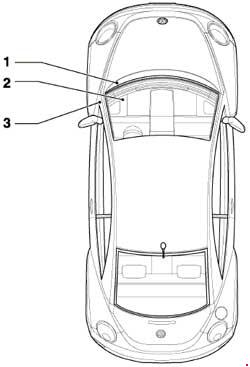
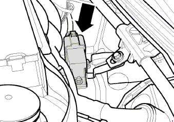
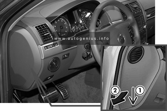
Fuse box location
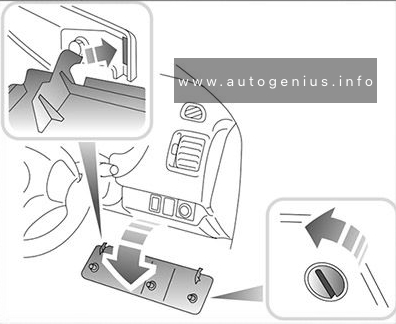
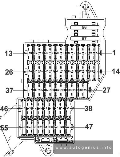
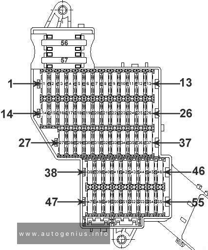
The fuse panel is located behind the cover on the driver’s side of dash panel.

- Switch off the ignition and the component concerned.
- Remove cover towards the front.
- With the aid of the list of fuses determine which fuse belongs to the component that has failed.
- Replace blown fuse – can be recognized by the burnt metal strip – with a fuse of same amperage.
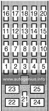
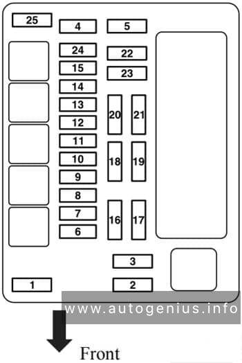
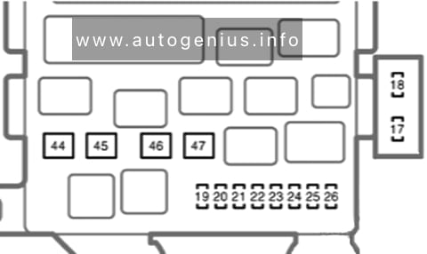
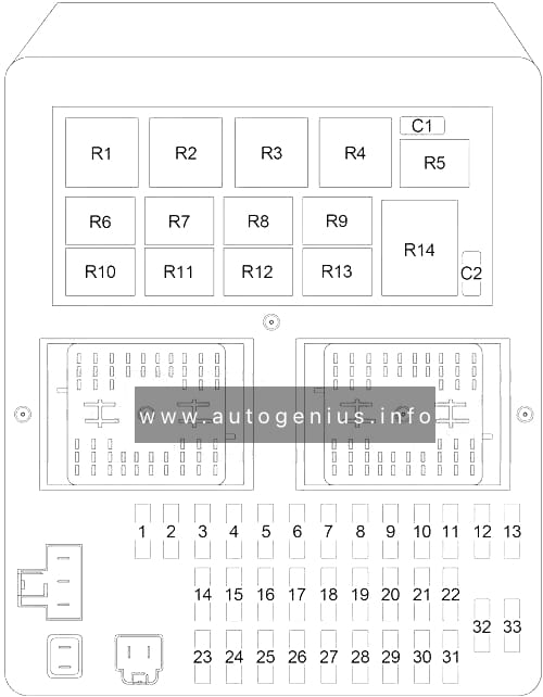
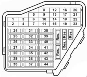
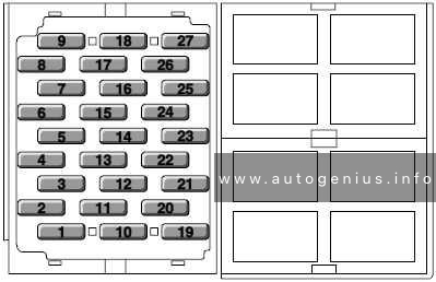
Fuse box diagram
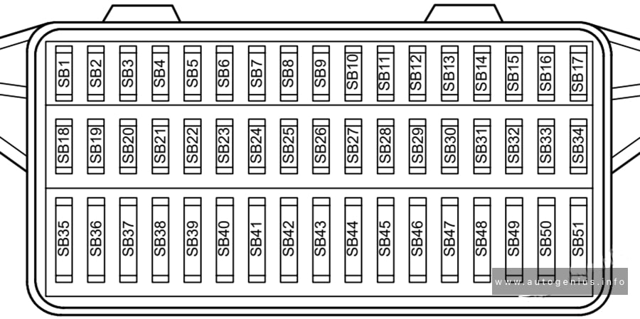
| № | Amps | Consumer |
|---|---|---|
| SB1 | 10A | Lambda probe heater / Air mass meter |
| SB2 | 5A | Number plate lights |
| SB3 | 5A/10A | Injectors Mapped controlled engine cooling thermostat, fuel metering valve, intake manifold flap air flow control valve, camshaft timing adjustment valve |
| SB4 | 5A | Left side lights |
| SB5 | 5A | Left side lights |
| SB6 | 15A | Rear wiper |
| SB7 | 7.5A | Turn signal system |
| SB8 | 5A | ABS/ESP |
| SB9 | 5A | Headlight range control |
| SB10 | 5A | Interior lights Self-diagnosis connection (3L) |
| SB11 | 5A | Self-diagnosis connection, dash panel insert, Climatronic, ESP control unit, Steering angle sender |
| SB12 | 10A | Right main beam, main beam warning lamp |
| SB13 | 10A | Left main beam |
| SB14 | 10A | Hazard warning system, anti-theft alarm system, remote control system |
| SB15 | 10A | Brake lights |
| SB16 | 5A | Radio Central locking and anti-theft alarm control unit Dash panel insert Ignition switch S-contact |
| SB17 | 5A | Folding mirrors |
| SB18 | 5A/15A | Mirror heating |
| SB19 | 15A | Dual tone horn, heated washer jets |
| SB20 | 5A/10A | CD changer, telephone |
| SB21 | 5A/10A/15A | Automatic gearbox control unit Electronic manual gearbox control unit |
| SB22 | 15A | ATA horn |
| SB23 | 5A | Supplementary heater relay, glow plug relays, throttle butterfly valve, exhaust gas regulation relay, speed sender, charge pressure sender |
| SB24 | 5A | Clutch pedal switch (diesel), brake light switch, Motronic control unit, radiator fan control unit |
| SB25 | 5A | Automatic gearbox selector lever, electric vent wing window |
| SB26 | 7.5A/5A | Central locking control unit, electrically adjustable exterior mirror, air conditioner, navigation, mobile telephone Mirror heating |
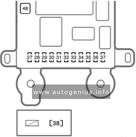
| SB27 | 5A | Dash panel insert |
| SB28 | 5A | Speedometer sender, immobilizer |
| SB29 | 7.5A | Reversing lights, washer jets heater elements, headlight range control |
| SB30 | 5A/7.5A | Exhaust gas recirculation valve, activated charcoal filter solenoid valve, heater tube, pressure control valve |
| SB31 | 10A | Engine control unit, electronic manual gearbox control unit |
| SB32 | 5A/10A | Engine control unit Crash fuel shut-off control unit |
| SB33 | 10A | Automatic gearbox control unit, electronic manual gearbox control unit |
| SB34 | 10A | Ignition transformer Speedometer sender |
| SB35 | 20A/25A | Sliding/tilting sunroof |
| SB36 | 15A | Simos (injection system) control unit, 4LV (injection system) control unit, electronic manual gearbox control unit |
| SB37 | 15A | Engine control unit Metering adjuster, electronic shut-off valve |
| SB38 | 25A | Left electric windows Left door control unit |
| SB39 | 25A | Right electric windows Right door control unit |
| SB40 | 15A | Fuel pump |
| SB41 | 15A | Central locking system control unit, anti-theft alarm system, remote control system |
| SB42 | 15A | Radio, navigation, CD changer |
| SB43 | 15A | Front fog lights, rear fog light |
| SB44 | 15A | Left dipped beam Headlight range control adjuster |
| SB45 | 15A | Right dipped beam |
| SB46 | 15A | Cigarette lighter |
| SB47 | 15A/20A/30A | Headlight washer system pump, gearbox hydraulic pump relay Horn (GTI) |
| SB48 | 20A | Heated rear window |
| SB49 | 25A | Fresh air blower |
| SB50 | 15A | Front wiper, windscreen washer pump |
| SB51 | 15A | Heated seats |
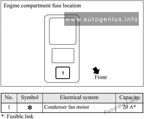
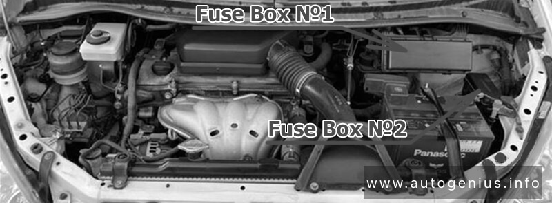
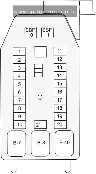
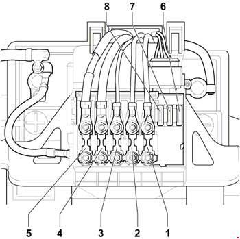
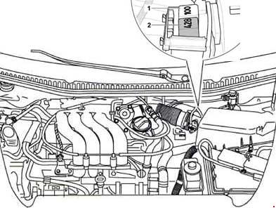
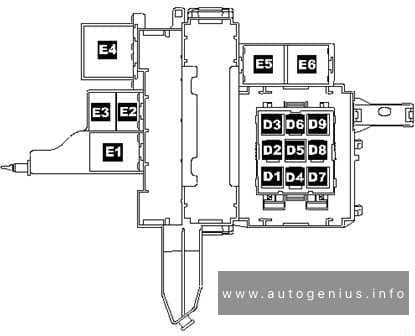
Engine Compartment
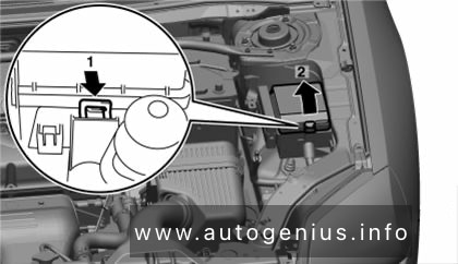
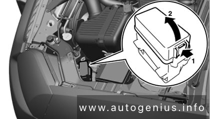
Fuse box location
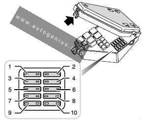
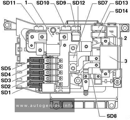
Fuse box placed on the battery of the engine compartment.
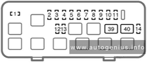
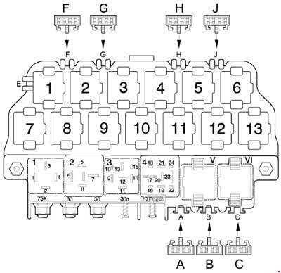
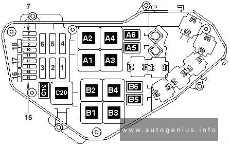
Fuse box diagram
Version 1
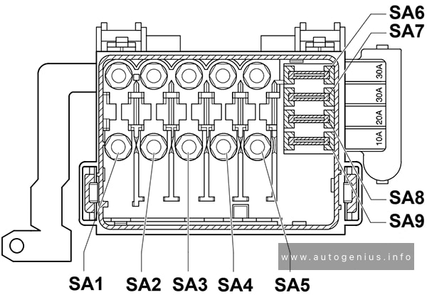
| № | Amps | Function/component |
|---|---|---|
| SA1 | 150A | Alternator |
| SA2 | 80A | Fuse carrier B Fuse SA2 is located in luggage compartment next to battery |
| SA3 | 50A | Engine glow plugs |
| SA4 | 80A | Electro-hydraulic power steering motor (ARR, AYZ) Coolant heater elements (ARR, AYZ) Radiator fan control unit (only models with air conditioner, ARR, AYZ) Radiator fan (ARR, AYZ) |
| SA5 | 30A | Radiator fan (AMF) |
| SA6 | 30A | ABS with EDL control unit |
| SA7 | 30A | ABS with EDL control unit |
| SA8 | 10A/20A | Radiator fan (AVY, ARR) Radiator fan control unit (only models with air conditioner, AVY, ARR) |
| SA9 | 30A/10A | Radiator fan control unit (only models with air conditioner, AVY, ARR) |
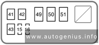
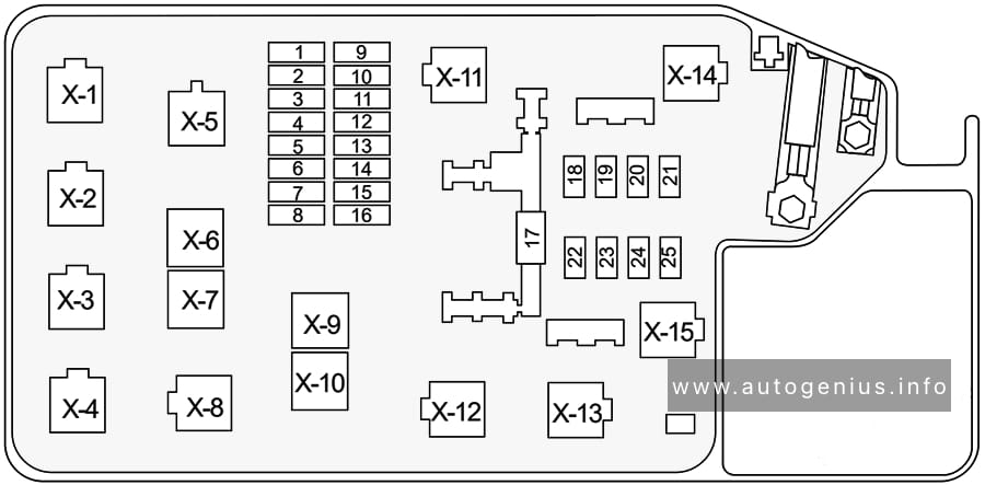
Version 2
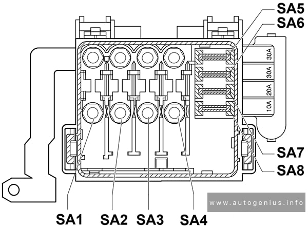
| № | Amps | Function/component |
|---|---|---|
| SA1 | 150A | Alternator |
| SA2 | 80A | Fuse carrier B Fuse SA2 is located in luggage compartment next to battery |
| SA3 | 50A | Engine glow plugs |
| SA4 | 80A | Electro-hydraulic power steering motor (ARR, AYZ) Coolant heater elements (ARR, AYZ) Radiator fan control unit (only models with air conditioner, ARR, AYZ) Radiator fan (ARR, AYZ) |
| SA5 | 30A | Radiator fan (AMF) |
| SA6 | 30A | ABS with EDL control unit |
| SA7 | 30A | ABS with EDL control unit |
| SA8 | 10A/20A | Radiator fan (AVY, ARR) Radiator fan control unit (only models with air conditioner, AVY, ARR) |
| SA9 | 30A/10A | Radiator fan control unit (only models with air conditioner, AVY, ARR) |
WARNING: Terminal and harness assignments for individual connectors will vary depending on vehicle equipment level, model, and market.