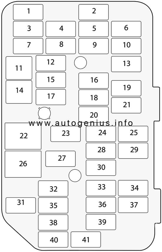
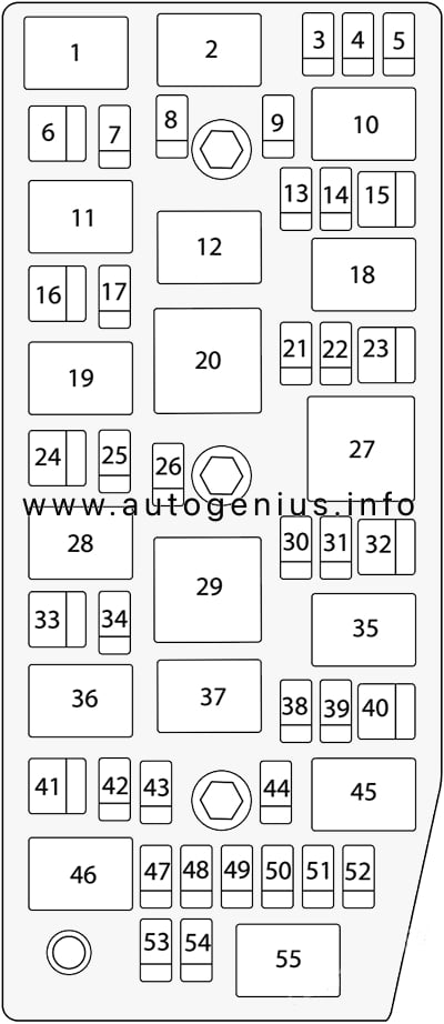
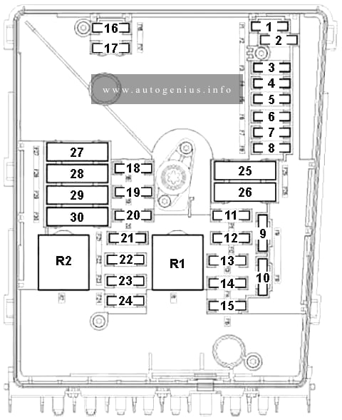
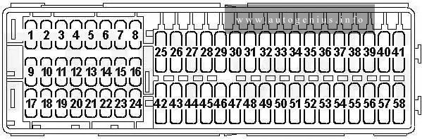
| No. |
A |
Function/component |
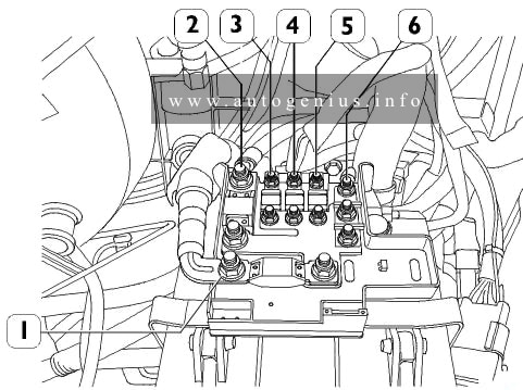
| 1 |
–
10 |
Not used (applicable up to May 2006)
10-pin connector -T10c- (from November 2006; for models with electric interface only) |
| 1 |
10
151) |
2-way radio switch -E72- (applies to special vehicles only)
Engine continues to run without key button -E489- (applies to special vehicles only)
Special vehicle control unit -J608- (up November 2006; applies to special vehicles only)
4-pin connector -T4g- (applies to special vehicles only) |
| 2 |
5 |
Fuel pump relay -J17- (BCA, BGU, BSE, BSF, BUD, BSX)
Terminal 15 voltage supply relay -J329- (BGU, BSE, BSF, BUD, BSX)
Data bus diagnostic interface -J533-
Engine control unit -J623- |
| 3 |
5 |
Headlight range control regulator -E102-
Left headlight range control motor -V48-
Right headlight range control motor -V49-
Traction control system switch -E132- (from November 2006)
TCS and ESP button -E256- (from November 2006)
Selector lever -E313- (from November 2006; only models with direct shift gearbox)
Brake light switch -F- (from November 2006)
ABS control unit -J104- (from November 2006)
Trailer detector control unit -J345- (from November 2006)
Power steering control unit -J500- (from November 2006; only models with power steering)
Selector lever sensors control unit -J587- (from November 2006; only models with direct shift gearbox)
Mechatronic unit for dual clutch gearbox -J743- (from November 2006; only models with direct shift gearbox) |
| 4 |
5 |
Mobile telephone operating electronics control unit -J412- (only models with telephone) |
| 5 |
15 |
Air mass meter -G70- (BLS, BSU, BJB, BDJ, BST)
Heater element for crankcase breather -N79- (BCA, BGU, BSE, BSF, BUD, BLS, BSU, BJB)
Reversing light switch -F4- (from November 2006)
Auxiliary heater operation relay -J485- (from November 2006; only models with auxiliary coolant heater)
16-pin connector -T16- (from November 2006; self-diagnosis connection) |
| 5 |
10 |
Heater element for crankcase breather -N79- (BSX)
Activated charcoal filter system solenoid valve 1 -N80- (BSX)
16-pin connector -T16- (from November 2006; self-diagnosis connection)
Reversing light switch -F4- (from November 2006)
Auxiliary heater operation relay -J485- (from November 2006; only models with auxiliary coolant heater) |
| 6 |
5 |
Airbag control unit -J234-
Front passenger side airbag deactivated warning lamp -K145- |
| 7 |
5 |
Heater/heat output switch -E16- (only models with seat heating and without central locking)
Air conditioning system control unit -J301- (only models with seat heating and without central locking)
Not used (from November 2006) |
| 8 |
5 |
Left washer jet heater element -Z20- (only models without central locking)
Right washer jet heater element -Z21- (only models without central locking)
Not used (from November 2006) |
| 9 |
10 |
Power steering control unit -J500- (only models with power steering)
Not used (from November 2006) |
| 10 |
10 |
Reversing light switch -F4-
Auxiliary heater operation relay -J485- (only models with auxiliary coolant heater)
16-pin connector -T16- (self-diagnosis connection)
Not used (from November 2006) |
| 11 |
– |
Not used (applicable up to May 2006) |
| 11 |
10 |
2-pin connector -T2ab- (applies to special vehicles only, applicable from June 2006) |
| 12 |
– |
Not used (applicable up to May 2006) |
| 12 |
5 |
Interior light switch (taxi) -E115- (only taxi)
Taxi sign switch -E138- (only taxi)
Hands-free system button -E487- (only taxi)
Taxi meter -G41- (only taxi) |
| 12 |
10 |
2-pin connector -T2ac- (applies to special vehicles only)
28-pin connector -T28a- (applies to special vehicles only) |
| 13 |
5 |
Trailer detector control unit -J345- (only models with trailer operation and without central locking)
Not used (from November 2006) |
| 14 |
5 |
Traction control system switch -E132-
TCS and ESP button -E256-
ABS control unit -J104-
Brake light switch -F- (applicable from June 2006)
Not used (from November 2006) |
| 15 |
5 |
Selector lever -E313- (only models with direct shift gearbox)
Selector lever sensors control unit -J587- (only models with direct shift gearbox)
Mechatronic unit for dual clutch gearbox -J743- (only models with direct shift gearbox)
Not used (from November 2006) |
| 16 |
5 |
Heater/heat output switch -E16- (only models without air conditioning system)
High pressure sender -G65- (only models with air conditioning system)
Oil level and oil temperature sender -G266- (only for models with flexible service interval display)
Control unit in dash panel insert -J285- |
| 17 |
7.5 |
Left tail light and rear fog light bulb -M41- (models without central locking)
Rear fog light cut-out contact switch -F216- (only models with trailer operation and without central locking) |
| 18 |
5 |
Not used (applicable up to May 2006)
Taxi alarm remote control, control unit -J601- (only taxi, applicable from June 2006)
10-pin connector -T10c- (for models with electric interface only) (from November 2006) |
| 19 |
5 |
Not used (applicable up to May 2006)
10-pin connector -T10c- (for models without electric interface only, applicable from June 2006) |
| 19 |
10 |
Taxi meter -G41- (only taxi, applicable from June 2006)
Two-way radio -R8- (only taxi, applicable from June 2006) |
| 20 |
5 |
Automatic gearbox control unit -J217- |
| 20 |
10 |
10-pin connector -T10c- (from November 2006; for models with electric interface only) |
| 21 |
5
101) |
Selector lever -E313- (only models with direct shift gearbox)
Selector lever sensors control unit -J587- (only models with direct shift gearbox)
Tiptronic switch -F189- (from November 2006; only models with direct shift gearbox)
Automatic gearbox control unit -J217- (from November 2006)
16-pin connector -T16- (from November 2006; self-diagnosis connection)
Light switch -E1- (from November 2006)
Heater/heat output switch -E16- (from November 2006)
Air conditioning system control unit -J301- (from November 2006)
Remote control receiver for auxiliary coolant heater -R149- (from November 2006; only models with remote control receiver for auxiliary coolant heater) |
| 22 |
5 |
Remote control receiver for auxiliary coolant heater -R149- (only models with remote control receiver for auxiliary coolant heater)
Not used (from November 2006) |
| 23 |
10 |
Brake light switch -F- (applicable up to May 2006) |
| 23 |
10 |
3-pin connector -T3r- (applies to special vehicles only, applicable from June 2006) |
| 24 |
10
51) |
Light switch -E1- (up November 2006)
Heater/heat output switch -E16- (up November 2006)
Air conditioning system control unit -J301- (up November 2006)
16-pin connector -T16- (up November 2006; self-diagnosis connection)
Interior monitoring sensor -G273- (from November 2006)
Vehicle inclination sender -G384- (from November 2006)
Alarm horn -H12- (from November 2006) |
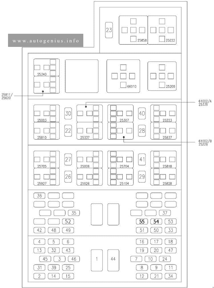
| 25 |
– |
Not used |
| 26 |
20 |
Injector, cylinder 1 -N30- (BCA, BGU, BSE, BSF, BUD)
Injector, cylinder 2 -N31- (BCA, BGU, BSE, BSF, BUD)
Injector, cylinder 3 -N32- (BCA, BGU, BSE, BSF, BUD)
Injector, cylinder 4 -N33- (BCA, BGU, BSE, BSF, BUD) |
| 27 |
20 |
Not used (up November 2006)
Automatic gearbox control unit -J217- , under front left wheel housing liner (from November 2006) |
| 28 |
5 |
Light switch -E1- (models with central locking) |
| 28 |
20 |
Rear fog light switch -E18- (from November 2006; only models without central locking) |
| 29 |
15 |
Rear window wiper motor -V12- (models with rear window wiper only) |
| 30 |
5 |
Heater/heat output switch -E16- (only models with seat heating and central locking)
Air conditioning system control unit -J301- (only models with seat heating and central locking) |
| 30 |
25 |
Light switch -E1- (only models without central locking) |
| 31 |
15 |
Onboard supply control unit -J519- |
| 32 |
5 |
Left washer jet heater element -Z20- (only models with central locking)
Right washer jet heater element -Z21- (only models with central locking) |
| 33 |
40 |
Heater/heat output switch -E16-
Air conditioning system control unit -J301-
Auxiliary heater operation relay -J485- (only models without auxiliary coolant heater) |
| 34 |
– |
Not used |
| 35 |
– |
Not used |
| 36 |
– |
Not used (applicable up to May 2006) |
| 36 |
20 |
10-pin connector -T10ai- (applies to special vehicles only, applicable from June 2006) |
| 37 |
15 |
Right dipped beam bulb -M31- (models without central locking) |
| 38 |
15 |
Left dipped beam bulb -M29- (models without central locking only) |
| 38 |
10 |
Fluorescent light in rear of high roof -W41- (applies to special vehicles only, applicable from June 2006)
Fluorescent light in centre of high roof -W42- (applies to special vehicles only, applicable from June 2006) |
| 39 |
– |
Not used |
| 40 |
20 |
Trailer detector control unit -J345- |
| 41 |
20 |
Trailer socket -U10- |
| 42 |
15 |
12 V socket -U5- (without 12 V socket, in luggage compartment) |
| 42 |
30 |
12 V socket -U5- (near handbrake lever)
12 V socket 2 -U18- (left luggage compartment) |
| 43 |
15 |
Electric fuel pump 2 relay -J49- (BCA, BGU, BSE, BSF, BUD, BSX)
Fuel pump relay -J17- (BDJ, BJB, BLS, BSU, BJB, BSE, BSF, BUD, BSX) |
| 44 |
5 |
Interior monitoring sensor -G273-
Vehicle inclination sender -G384-
Alarm horn -H12-
Not used (from November 2006) |
| 45 |
5 |
Aerial selection control unit -J515- (applicable up to May 2006) |
| 45 |
20 |
Headlight washer system relay -J39- (from November 2006; only models with headlight washer system)
Headlight washer system pump -V11- (from November 2006; only models with headlight washer system) |
| 45 |
30 |
10-pin connector -T10ai- (applies to special vehicles only, applicable from June 2006) |
| 46 |
7.5 |
Onboard supply control unit -J519- (Interior light) |
| 47 |
25 |
Cigarette lighter -U1- |
| 48 |
20 |
Headlight washer system relay -J39- (up November 2006)
Headlight washer system pump -V11- (up November 2006) |
| 48 |
30 |
Heated front seats control unit -J774- (from November 2006; only models with lateral support heater) |
| 49 |
10 |
Driver door control unit -J386- (only models with central locking)
Front passenger door control unit -J387- (only models with central locking) |
| 50 |
25 |
Convenience system central control unit -J393- |
| 51 |
30 |
Heated driver seat control unit -J131- (up November 2006)
Heated front passenger seat control unit -J132- (up November 2006)
Heated front seats control unit -J774- |
| 52 |
25 |
Fresh air blower relay -J13- (only models with auxiliary heater)
Onboard supply control unit -J519-
Heated rear window -Z1- |
| 53 |
– |
Not used |
| 54 |
– |
Not used |
| 55 |
– |
Not used |
| 56 |
– |
Not used |
| 57 |
5 |
Not used (applicable up to May 2006)
Accident data memory -J754- (applies to special vehicles only, applicable from June 2006)
10-pin connector -T10c- (from November 2006; for models with electric interface only) |
| 58 |
10 |
Not used (applicable up to May 2006)
4-pin connector -T4g- (applies to special vehicles only, applicable from June 2006) |
| 1) from November 2006 |