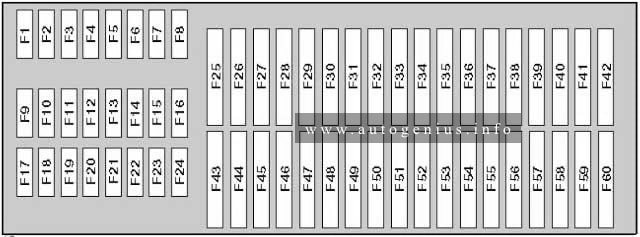
Year of production: 2011, 2012, 2013, 2014, 2015, 2016
The Holden Captiva 5 (CG-II, facelifted), a compact crossover SUV, was manufactured between 2011 and 2016. This article provides fuse box diagrams for the 2011, 2012, 2013, 2014, 2015, and 2016 models. You’ll also find details about the location of the fuse panels within the vehicle and learn about the fuse and relay assignments (fuse layout).
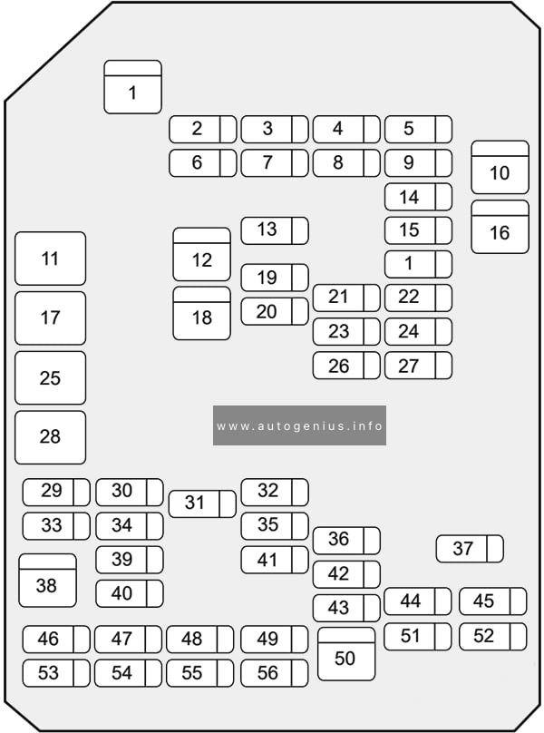
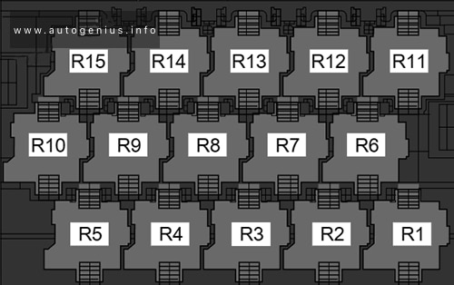
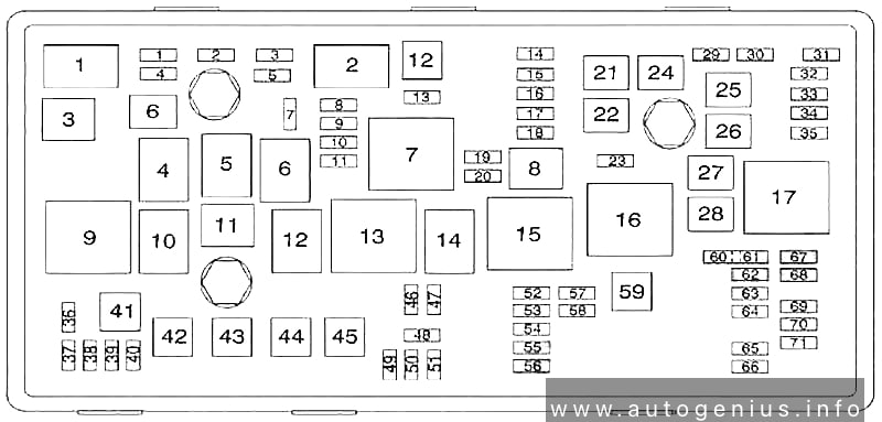
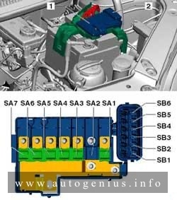
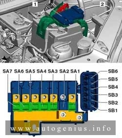
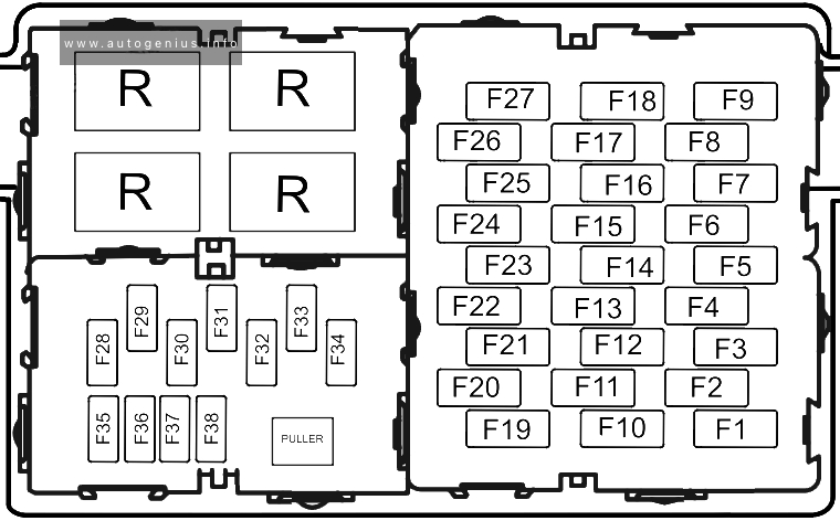
Passenger Compartment Fuse Box
Fuse Box Location
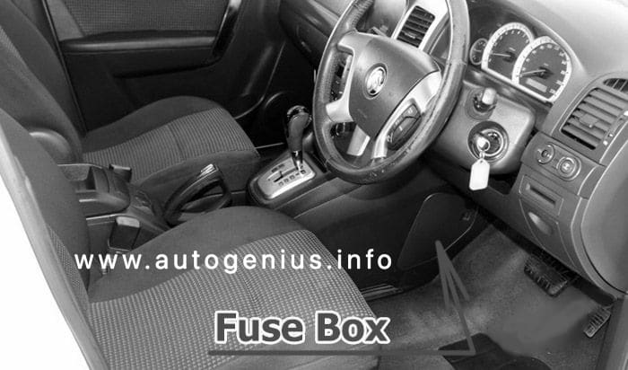
The fuses are located on the left-hand side of the driver’s side footwell. To open the fuse cover, pull the latch rearwards to disengage the cover.
Assignment of the fuses in the passenger compartment
№
Amps
Description
1
30A
DRVR PWR SEAT
2
10A
S/ROOF FOLDING MIRROR
3
20A
FSCM / VENT SOL
4
15A
F/DOOR LOCK
5
20A
DR/LCK
6
20A
TRLR
7
20A
APO JACK (CONSOLE)
8
20A
HTD SEAT PWR / REAR A/C
9
15A
BCM (PRK/TRN)
10
30A
PASS PWR WNDW
11
ACC/RAP RELAY
12
20A
2011-2013: S/ROOF BATT
13
20A
CIGAR
14
15A
BCM (STOP)
15
15A
BCM (CTSY)
16
20A
DRV PWR WNDW
17
CIGAR / APO JACK RELAY
18
20A
2014-2016: S/ROOF BATT
19
20A
APO JACK REAR CARGO
20
15A
RUN/CRANK
21
SPARE
22
30A
AMP (audio system)
23
15A
BCM (TRN SIG)
24
15A
DRL
25
RUN RELAY
26
20A
FRT WSR
27
10A
L/GATE
28
RUN/CRANK RELAY
29
20A
HEATING MAT SW
30
10A
FSCM
31
15A
AWD/VENT
32
15A
2015-2016: RR HEAT SEAT
33
10A
RUN2
34
5A
ISRVM/RCM
35
15A
RR FOG
36
15A
BCM (DIMMER)
37
15A
LOGISTIC MODE
38
40A
HVAC BLWR
39
10A
CLSTR
40
10A
SDM (IGN 1)
41
5A
PWR DIODE
42
10A
2011-2014: XBCM
2015-2016: BCM (VBATT)
43
30A
TRLR BATT
44
15A
RVS / HVAC / DLC
45
2A
PWR / MODING
46
10A
SSPS
47
10A
XBCM
48
20A
BCM (INT LIGHT) / TRLR FOG
49
10A
IPC
50
30A
2015-2016: DC DC CONVERTER
51
10A
SDM (BATT)
52
SPARE
53
2A
OSRVM
54
10A
AUDIO / KEY CAPTURE
55
SPARE
56
2A
STR/WHL SW
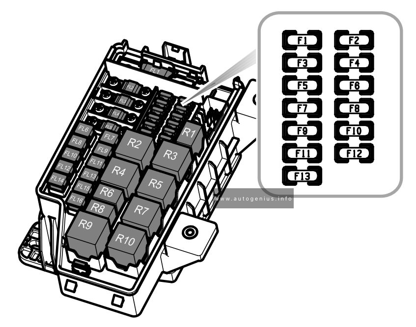
Engine Compartment Fuse Box
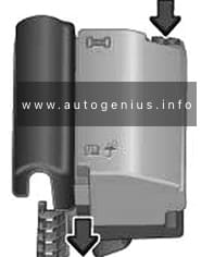
Fuse Box Location
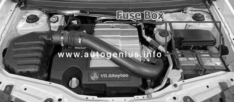
This fuse box is located toward the rear of the engine compartment next to the coolant reservoir, it contains circuit fuses, main fuses and relays. To remove the cover, press the catch on the side of the fuse box toward the engine and release the two tabs at the opposite side.
Year of production: 2010, 2011, 2012, 2013, 2014, 2015, 2016, 2017
This article covers the sixth-generation Volkswagen Jetta (A6, Typ 1B), produced from 2010 to 2017. It provides fuse box diagrams for the 2010, 2011, 2012, 2013, 2014, 2015, 2016, and 2017 models, details the locations of the fuse panels inside the vehicle, and explains the function of each fuse (fuse layout) and relay.
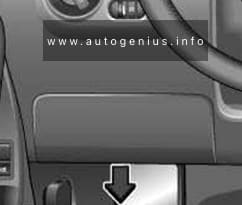
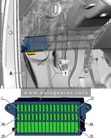
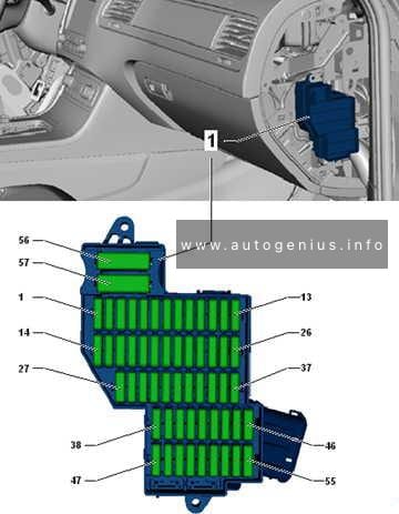
Passenger Compartment Fuse Box
Fuse Box Location
The fuse box is located behind the cover on the driver’s side. Pull the lower part of the cover in the direction of the arrow and remove the cover from the bottom. On the inside of the cover there are plastic tweezers for removing and inserting fuses.
Volkswagen Jetta (A6; 2010 – 2017) – fuse and relay diagram – passenger compartment (holder C)
Assignment of the fuses in the instrument panel (holder C)
№
Amps
Function/Component
F1
10A
2014-2017: Left washer nozzle heater Right washer nozzle heater
F2
5A/7,5A
Electronic steering column lock control module
F3
10A
Instrument cluster control module
F4
2A/10A
2012-2017: Telephone Transceiver Compass magnetic field sensor (vehicles equipped with Start/Stop)
F5
7.5A
2012-2017: Left rear fog lamp bulb
F6
10A
Vehicle electrical system control module (T73a/66) (interior lamp, AW0 only) Rearview camera (2014-2017)
F7
5A
Fog lamp relay (AW0 only) Instrument panel and switch illumination dimmer switch (AW0 only) License plate lamp Vehicle electrical system control module (T52c/27), (AW1 only)
F8
7.5A
Windshield and headlamp washer pump switch (AW0 only) Windshield washer pump (AW0 only) Vehicle electrical system control module (T73b/61), (AW0 only)
F8
–
not used (AW1 only)
F9
5A/15A
Arbag control module Airbag Control Module Front passenger airbag “disabled” indicator lamp Passenger occupant detection system control module
F10
10A
Right steering column switch (T10ls/3) (AW0 only)
F11
10A
2012-2017: Left front headlamp (HID headlamp)
F12
10A
2012-2017: Right front headlamp (HID headlamp)
F13
5A
Automatic dimming interior rearview mirror Light recognition sensor Parking aid control module Ar quality sensor High pressure sensor Climatronic control module Tire pressure monitoring button ASR/ESP button Back-up lamp switch Start/Stop mode switch 28-pin connector (T28/10) Mirror adjusting switch Exterior rearview mirror heating switch AC compressor control module (T14hy/14) (Engine code CNLA) Cornering lamp and headlamp range control module
F14
10A
Left steering column switch (T16ls/1) (AW0 only) ABS control module T26/20 / T47/8 Light switch (T10h/4) (AW1 only) Arbag spiral spring/return spring with slip ring (T16k/14) Fuel pump control module Towing recognition control module (T12a/2) Voltage stabilizer Converter with socket, 12V-230V (T3wr/3) Data bus on board diagnostic interface (AW1 only) Instrument cluster control module Selector lever sensor system control module Tiptronic switch (T10s/9) Power steering control module (T6z/1) Oil level thermal sensor (T6z/4) Hybrid battery unit (T14ax/7) (Engine code CNLA) Electric drive power and control electronics (T28jx/56) (Engine code CNLA)
F15
10A
16-pin connector (diagnostic connection) Instrument panel and switch illumination dimmer switch Headlamp range control adjuster (AW1 only) Fresh air blower relay Mass airflow sensor Positive crankcase ventilation heating element – Structure borne sound control module Left front headlamp Left headlamp beam adjustment motor Right front headlamp Right headlamp beam adjustment motor Vehicle electrical system control module (T73a/44)
F16
10A
Auxiliary engine coolant pump relay Fuel pump control module Engine control module Electric drive button (Engine code CNLA)
F17
10A
2012-2017: Anti-theft alarm system horn (Running change) Anti-theft alarm system interior sensor (Running change) Anti-theft alarm system alarm (Running change)
F18
15A
Left front headlamp Left low beam headlamp bulb (vehicles with China equipment)
F19
15A
Right front headlamp Right low beam headlamp bulb (vehicles with China equipment)
F20
10A
Ignition/starter switch (T10/10) (AW0 only) Tiptronic switch Automatic transmission control module Selector lever sensor system control module Climatronic control module Auxiliary engine coolant heater radio frequency receiver
F21
15A/20A
2012-2017: Vehicle electrical system control module (T73a/73), (AW0 only) Dual tone horn relay (AW1 only) High tone horn (AW1 only) Low tone horn (AW1 only)
Heater/heat output switch Fresh air blower relay AC control module Fresh air blower switch
F34
15A
Left high beam headlamp bulb (AW0 only) Right high beam headlamp bulb (AW0 only) Instrument cluster control module (AW0 only)
F35
10A
Steering column electronics control module (AW1 only) Data bus on board diagnostic interface (AW1 only) Instrument cluster control module (2010-2011) Signal horn activation (2010-2012)
F36
25A
Vehicle electrical system control module (T73a/16) (AW0 only) (T52b/1) (AW1 only) Vehicle electrical system control module (T73a/61) (AW0 only) (Running change)
F37
15A
Left front headlamp Left daytime running lamp bulb
F38
15A
Right front headlamp Right daytime running lamp bulb
F39
20A
Low beam relay
F40
15A
Towing recognition control module (T12a/9)
F41
15A
Towing recognition control module (T12a/12)
F42
20A
Towing recognition control module (T12a/11)
F43
30A
Front passenger door control module
F44
25A/30A
Rear window defogger relay (AW1 only) Rear window defogger Vehicle electrical system control module (T73b/67) (AW0 only)
F45
30A
Driver door control module Front passenger door control module (vehicles with China equipment)
F46
30A
Left rear door control module Right rear door control module
F47
15A
Fuel pump control module Fuel pump relay Fuel primer relay
F48
20A
Vehicle electrical system control module
F49
40A
Fresh air blower Climatronic control module A/C control module
Engine control module Engine component power supply relay
F3
5A/10A
Coolant fan control module Relay for low heat output Relay for high heat output
F4
5A/10A/15A
Oxygen sensor heater Heater for oxygen sensor 1 after catalytic converter High temperature circuit coolant pump (Engine codes CNLA, CRJA) Low temperature circuit coolant pump
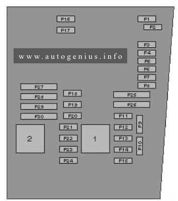
Volkswagen Golf VII (mk7; 2013 – 2020) – fuse and relay box diagram
Year of production: 2013, 2014, 2015, 2016, 2017, 2018, 2019, 2020
Overview of fuse holder
Volkswagen Golf VII (mk7; 2013 – 2020) – fuse and relay box location – overview of fuse holder
№
Description
1
Fuse panel C -SC-
2
Fuse panel B -SB-
3
Fuse panel A -SA-
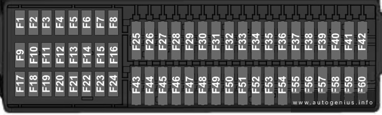
Passenger Compartment Fuse Box
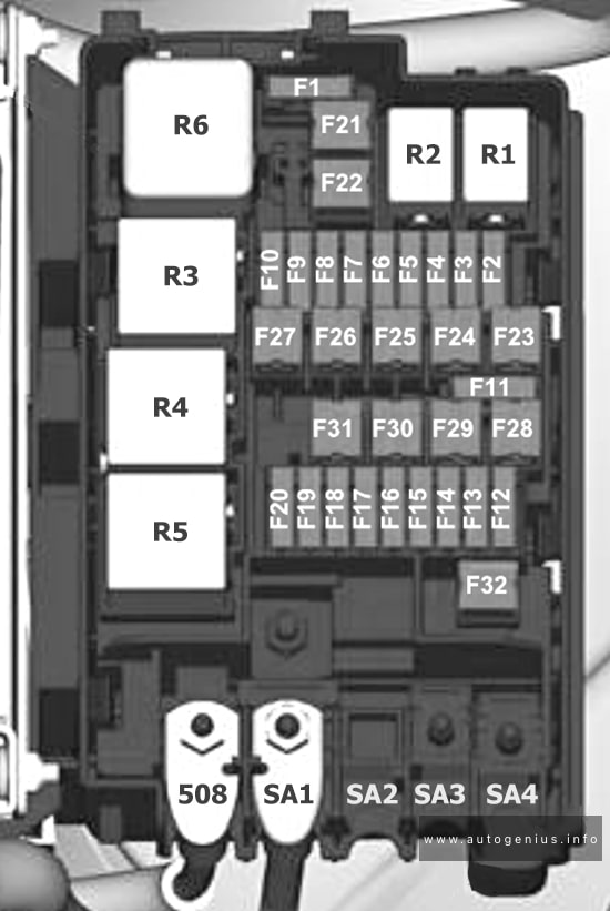
Fuse Box Diagram (Fuse Panel C- SC)
Volkswagen Golf VII (mk7; 2013 – 2020) – fuse and relay box location – passenger compartment (fuse panel C -SC-)
Fuse assignment fuse panel C -SC-
№
Designation in Wiring Diagram
A
Component
Terminal
F1
—
—
—
—
F2
—
—
—
—
F3
—
—
—
—
F4
Fuse 4 on fuse panel C -SC4-
10
Vehicle electrical system control module -J519-,
Anti-theft alarm system
30
F5
Fuse 5 on fuse panel C -SC5-
5
Data bus on board diagnostic interface -J533-
30
F6
Fuse 6 on fuse panel C -SC6-
5
Anti-theft alarm system sensor -G578-
30
F7
Fuse 7 on fuse panel C -SC7-
10
Heater and A/C controls -EX21-
Heater control module -J65-
Climatronic control unit -J255-
A/C control module -J301-
Selector lever -E313-
Auxiliary engine coolant heater radio
frequency receiver -R149-
Rear window defogger relay -J9-
Electronic steering column lock control module
-J764-
30
F16
Fuse 16 on fuse panel C -SC16-
7,5
Mobile communication 2-way signal amplifier -J984-
Antenna amplifier 3 -R112-
Voltage converter for USB charge module -A5-
30
F17
Fuse 17 on fuse panel C -SC17-
5
Instrument cluster control module -J285-
Instrument cluster -KX2-
30
F18
Fuse 18 on fuse panel C -SC18-
7,5
Rearview camera -R189-
Rear lid unlock switch -E165-
30
F19
Fuse 19 on fuse panel C -SC19-
7,5
Access/start system interface -J965-
30
F20
—
—
—
—
F21
—
—
—
—
F22
—
—
—
—
F23
Fuse 23 on fuse panel C -SC23-
40
Vehicle electrical system control module -J519-
Right front headlamp -MX2-
30
F24
Fuse 24 on fuse panel C -SC24-
30
Power sunroof control module -J245-
30
F25
Fuse 25 on fuse panel C -SC25-
30
Driver door control module -J386- 1)
Left rear window regulator motor -V26- 1)
Front passenger door control module -J387- 2)
Right rear window regulator motor -V27- 2)
30
F26
Fuse 26 on fuse panel C -SC26-
20
Vehicle electrical system control module -J519-
Front heated seat
30
F27
Fuse 27 on fuse panel C -SC27-
30
Digital Sound System Control Module -J525-
30
F28
Fuse 28 on fuse panel C -SC28-
20
Towing recognition control module -J345-
30
F29
—
—
—
—
F30
Fuse 30 on fuse panel C -SC30-
25
Left front seat belt tensioner control module -J854-
30
F31
Fuse 31 on fuse panel C -SC31-
40
Vehicle electrical system control module -J519-
Left front headlamp -MX1-
30
F32
Fuse 32 on fuse panel C -SC32-
7,5
Driver assistance systems front camera -R242-
Distance regulation control module -J428-
Parking aid control module -J446-
Parallel parking assistance control module –
J791-
15
F33
Fuse 33 on fuse panel C -SC33-
5
Airbag control module -J234-
15
Front passenger airbag -disabled- indicator
lamp -K145-
Diagnostic connection -U31-
Headlamp range control and instrument
illumination regulator -EX14-
Automatic dimming interior rearview mirror -Y7
–
Cornering lamp and headlamp range control
module -J745-
Left headlamp beam adjustment motor -V48-
Right headlamp beam adjustment motor -V49-
15
F36
Fuse 36 on fuse panel C -SC36-
10
Right daytime running lamp and parking lamp
control module -J861-
15
F37
Fuse 37 on fuse panel C -SC37-
10
Left daytime running lamp and parking lamp
control module -J860-
15
F38
Fuse 38 on fuse panel C -SC38-
20
Towing recognition control module -J345-
30
F39
Fuse 39 on fuse panel C -SC39-
30
Front passenger door control module -J387-
Right rear window regulator motor -V27- 1)
Driver door control module -J386- 2)
Left rear window regulator motor -V26- 2)
30
F40
Fuse 40 on fuse panel C -SC40-
20
Cigarette lighter -U1-3)
12 V socket -U5-
12 V socket 2 -U18-
12 V socket 3 -U19-
15/30 4)
F41
Fuse 41 on fuse panel C -SC41-
10
Steering column electronics control module -J527-
30
F42
Fuse 42 on fuse panel C -SC42-
40
Vehicle electrical system control module -J519-
Central locking system
30
F43
Fuse 43 on fuse panel C -SC43-
30
Vehicle electrical system control module -J519-
30
F44
Fuse 44 on fuse panel C -SC44-
15
Towing recognition control module -J345-
30
F45
Fuse 45 on fuse panel C -SC45-
15
Driver seat lumbar support adjustment switch -E176-
Driver seat adjustment control head -E470-
Front passenger seat adjustment control head -E471-
Front passenger seat lumbar support adjustment switch -E177-
Fuel pressure regulator valve -N276-1)
Charge air cooling pump -V188-1)
Oil pressure regulation valve -N428-2)
Cooling circuit solenoid valve -N492-2)
Charge air cooling pump -V188-2)
Heater support pump -V488- 2)
87
10 2)
F8
Fuse 8 on fuse panel B -SB8-
10 1)
Oxygen sensor heater -Z19-
Oxygen sensor 1 before catalytic converter -GX10-
Heater for oxygen sensor 1 after catalytic converter -Z29-
Oxygen sensor 1 after catalytic converter -GX7-
Mass airflow sensor -G70-
87
F9
Fuse 9 on fuse panel B -SB9-
5 2)
Ignition coil 1 with power output stage -N70- 1)
Ignition coil 2 with power output stage -N127-1)
Ignition coil 3 with power output stage -N291-
1)
Ignition coil 4 with power output stage -N292-1)
Automatic glow time control module -J179- 2)
Early fuel evaporation heating element -N51- 2)
87
20 1)
F10
Fuse 10 on fuse panel B -SB10-
15 1)
Fuel pump control module -J538-
87
20 2)
F11
Fuse 11 on fuse panel B -SB11-
40
Auxiliary heater heating element -Z35-
87
F11
Fuse 11 on fuse panel B -SB11-
40
Auxiliary heater heating element -Z35-
87
F12
Fuse 12 on fuse panel B -SB12-
40
Auxiliary heater heating element -Z35-
87
F13
Fuse 13 on fuse panel B -SB13-
30
DSG transmission Mechatronic -J743-
30
F14
—
—
—
—
F15
Fuse 15 on fuse panel B -SB15-
15
Horn relay -J413-
30
F16
—
—
—
—
F17
Fuse 17 on fuse panel B -SB17-
7,5
Motronic engine control module power supply
relay -J271- 1)
Terminal 30 power supply relay -J317-2)
Engine control module -J623-
ABS control module -J104-
30
F18
Fuse 18 on fuse panel B -SB18-
5
Battery monitoring control module -J367-
Data bus on board diagnostic interface -J533-
3)
30
F19
Fuse 19 on fuse panel B -SB19-
30
Wiper motor control module -J400-
30
F20
Fuse 20 on fuse panel B -SB20-
20
Anti-theft alarm system horn -H8-
30
F21
—
—
—
—
F22
Fuse 22 on fuse panel B -SB22-
5
Engine control module -J623-
50
F23
Fuse 23 on fuse panel B -SB23-
30
Starter -B-
50
F24
Fuse 24 on fuse panel B -SB24-
40
Auxiliary heater heating element -Z35-
87
F25
—
—
—
—
F26
—
—
—
—
F27
—
—
—
—
F28
—
—
—
—
F29
—
—
—
—
F30
—
—
—
—
F31
—
—
—
—
F32
—
—
—
—
F33
—
—
—
—
F34
—
—
—
—
F35
—
—
—
—
F36
—
—
—
—
F37
Fuse 37 on fuse panel B -SB37-
20
Auxiliary heater control module -J364-
30
F38
—
—
—
—
1) Only for vehicles with gasoline engine
2) only for vehicles with a diesel engine
3) Only for vehicles without Stop/Start
Engine Compartment Fuse Box
Fuse Box Diagram (Fuse Panel A- SA)
Volkswagen Golf VII (mk7; 2013 – 2020) – fuse and relay box location – engine compartment (fuse panel A -SA-)
Fuse assignment fuse panel A -SA-
№
Designation in Wiring Diagram
A
Component
Terminal
J
Fuse 1 on fuse panel A -SA1-
100
Fuses Supply:
-SC4- …-SC14-
-SC30-
-SC31-
-SC38-
-SC39-
-SC41-
-SC42-
-SC53-
Front passenger power seat adjustment
circuit breaker 1 -S46-
Terminal 15 power supply relay -J329-
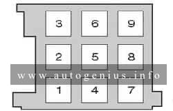
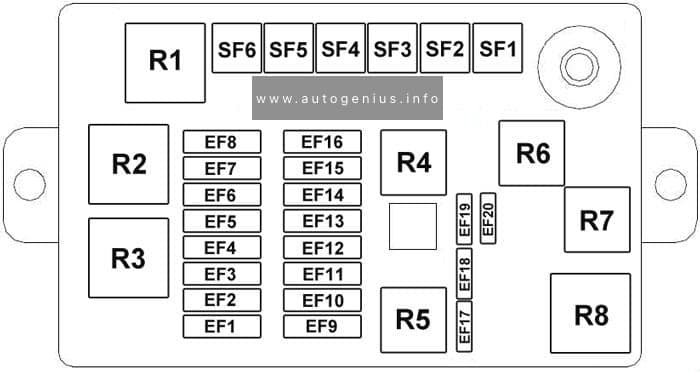
Chevrolet Cruze (J300; 2008 – 2016) – fuse and relay box diagram
Year of production: 2008, 2009, 2010, 2011, 2012, 2013, 2014, 2015, 2016
This article focuses on the first-generation Chevrolet Cruze (J300), manufactured between 2008 and 2016. It includes fuse box diagrams for the 2008 to 2016 models, provides details on the locations of the fuse panels inside the vehicle, and explains the function and layout of each fuse and relay.
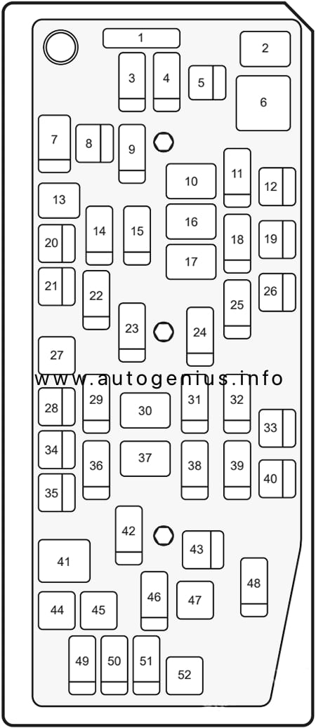
Engine compartment fuse box
Fuse box diagram
Chevrolet Cruze (J300; 2008 – 2016) – fuse and relay box diagram – engine compartment
Assignment of the fuses and relay in the engine compartment
No.
A
Description
1
15
Transmission Control Module
2
15
Engine Control Module
3
N/A
Not Used
5
15
Transmission Control Module, Engine Control Module, Mass Air Flow/Intake Air Temperature Sensor, Output Speed Sensor
Volkswagen Tiguan (2008-2017) – fuse and relay box diagram
Year of production: 2008, 2009, 2010, 2011, 2012, 2013, 2014, 2015, 2016, 2017
This article covers the first-generation Volkswagen Tiguan, manufactured from 2007 to 2017. It includes fuse box diagrams for the 2008 to 2017 models, provides details on the location of the fuse panels inside the vehicle, and explains the function and layout of each fuse and relay.
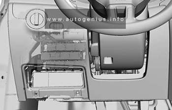
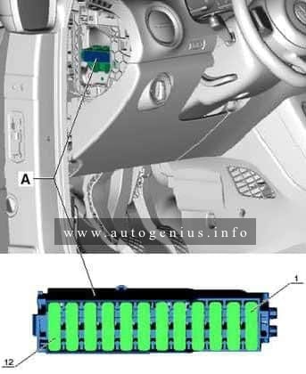
Passenger compartment
Fuse box location
The fuse box is located behind the storage compartment below the steering wheel.
Assignment of the fuses in the instrument panel (fuse panel)
№
A
Circuits protected
1
–
2
–
3
–
4
–
5
–
6
–
7
–
8
–
9
5
Supplementary restraint system (SRS) control module
10
10
Four wheel drive control module
11
5
Parking aid control module, self-parking system control module
12
10
Gas discharge headlamp control module (LH)
13
5
ABS/ESP system, AC system, anti-dazzle interior mirror, heated windscreen washer jets, seat occupation control module, transmission control module (TCM), reversing lamps, engine management system
14
10
ABS control module, engine control module (ECM), heated seats, power steering control module, suspension control module, trailer control module, AC control module, instrumentation control module, CAN data bus gateway control module
15
10
Auxiliary heater, data link connector (DLC), parking brake control module, engine management, headlamp direction control module
16
10
Gas discharge headlamp control module (RH)
17
5
Instrument panel
18
10
Mobile telephone control module, multimedia control module
19
10
Steering column function control module 2
20
5
ABS control module, AC system, transmission control module (TCM)
21
15
Door function control module, left rear, door function control module, right rear, multifunction control module 2
22
5
Alarm system, multifunction control module 2
23
10
ABS/ESP system, AC system, data link connector (DLC), rear view camera control module, headlamp switch
24
10
Door function control module, driver, door function control module, passenger
25
20
Transmission control module (TCM)
26
–
27
–
28
40
AC control module, auxiliary heater
29
15
Rear screen wiper motor
30
–
31
20
Auxiliary power sockets, cigarette lighter
32
–
33
–
34
–
35
–
36
–
37
–
38
10
Steering column function control module 1
39
20
Headlamp washers
40
15
Trailer control module
41
15
Trailer control module
42
20
Trailer control module
43
25
Sunroof control module
44
25
Parking brake control module
45
25
Heater blower motor, heated rear window
46
30
Door function control module, driver, door function control module, passenger
47
30
Door function control module, driver, door function control module, right rear
Year of production: 2011, 2012, 2013, 2014, 2015, 2016, 2017
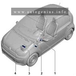
The city car Volkswagen Up is available from 2011 to the present. In this article, you will find fuse box diagrams of Volkswagen Up 2011, 2012, 2013, 2014, 2015, 2016 and 2017, get information about the location of the fuse panels inside the car, and learn about the assignment of each fuse (fuse layout).
Onboard supply control unit -J519-
• Light switch -E1- Dipped beam/daytime running lights/main beam
5
5
7.5*1
Onboard supply control unit -J519-
• Ignition/starter switch -D-
CCS switch -E45-
6
5
7.5*1
Headlight range control regulator -E102-
Left headlight range control motor -V48-
Right headlight range control motor -V49-
Mirror adjustment switch -E43-
7
10
Selector lever -E313-
8
7.5
Automated manual gearbox control unit -J514-
Selector lever -E313-
9
7.5
Airbag control unit -J234-
Centre switch module 2 in dash panel -EX35-
10
5
7.5*1
Parking aid control unit -J446-
11
10
Right headlight dipped beam bulb -M31-
12
5
7.5*1
Dash panel insert -K-
Rear left fog light bulb -L46-
Control unit in dash panel insert -J285-*1
Onboard supply control unit -J519-*1
13
10
Left headlight dipped beam bulb -M29-
14
15
Rear window wiper motor -V12-
15
15
Light switch -E1-
16
5
7.5*1
Terminal 15 voltage supply relay -J329-
Power steering control unit -J500-
17
15
Washer pump switch (automatic wash/wipe and headlight washer system) -E44-
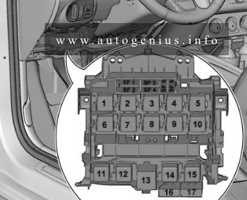
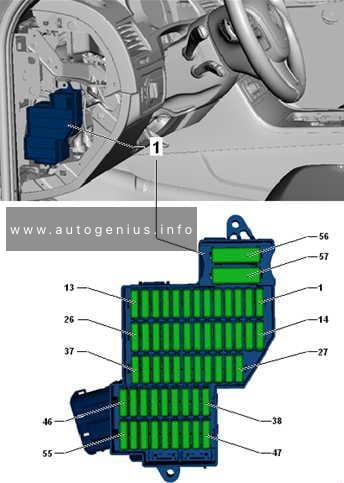
Audi A1 (8X; 2010 – 2018) – fuse and relay box diagram
Year of production: 2010, 2011, 2012, 2013, 2014, 2015, 2016, 2017, 2018
In this article, we take a look at the first-generation Audi A1 (8X), manufactured from 2010 to 2018. You will find fuse box diagrams for Audi A1 models from 2010 through 2018, learn where the fuse panels are located inside the vehicle, and discover the function of each fuse and relay (fuse layout).
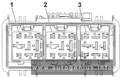
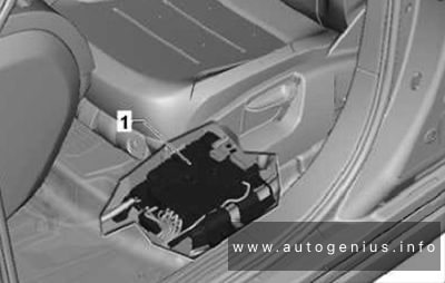
Location
Audi A1 (8X; 2010 – 2018) – fuse and relay box location
Fuse holder D -SD-
Fuse holder A -SA-
Fuse holder C -SC-
Relay/fuse holder F -SF-
Fuse holder B -SB-, Fuse holder H -SH-
Fuse holder B -SB-
Luggage compartment (Fuse holder A -SA-)
At battery positive terminal (for models with battery in luggage compartment only).
Fuse box diagram
Audi A1 (8X; 2010 – 2018) – fuse and relay box diagram – luggage compartment (holder A)
Assignment of the fuses in the luggage compartment (fuse holder A)
No.
A
Function/component
1
–
Vacant
2
110
Onboard supply
Engine component supply
3
–
Vacant
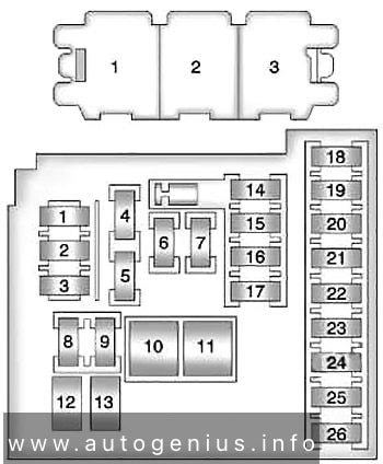
Engine comparmtnet (Fuse holder B -SB-)
Fuse box diagram (for models with battery in engine compartment)
Audi A1 (8X; 2010 – 2018) – fuse and relay box diagram – engine compartment (holder B)
Fuse box diagram (for models with battery in luggage compartment)
Audi A1 (8X; 2010 – 2018) – fuse and relay box diagram – engine compartment (holder B)
Assignment of the fuses in the engine compartment
No.
A
Function/component
1
175
Alternator -C-
2
40
Low heat output relay -J359-
Heater element for auxiliary air heater -Z35-
3
110 1)
Onboard supply1)
Engine component supply1)
4
80
Power steering control unit -J500-
5
50 2)
40 3)
Radiator fan thermal switch -F18-
Radiator fan control unit -J293-
6
50
Automatic glow period control unit -J179-
7
60
High heat output relay -J360-
Battery monitor control unit -J3671)
Auxiliary heater element -Z35-
1) for models with battery in engine compartment only
2) no longer fitted, phased out (model year 2011)
3) phased-in modification (model year 2011)
Engine comparment
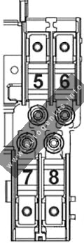
Fuses in electronics box in fuse holder B -SB-/ Fuse holder H -SH-
Fuse box diagram
In electronics box, in left engine compartment.
For S1 version models only, from January 2014, For models from November 2014 only.
Audi A1 (8X; 2010 – 2018) – fuse and relay box diagram – engine compartment (holder B/holder H)
Fuses in the electronics box
No.
A
Function/component
1
110 4)
5 5)
Onboard supply4)
Engine component supply4)
Radiator fan control unit -J293-5)
Radiator fan -V7-5)
2
250
Alternator -C-
Voltage regulator -C1-
3
–
Battery +
4
80
Power steering control unit -J500-
5
50 6)
Automatic glow period control unit -J179-6)
Glow plug 1 -Q10-
Glow plug 2 -Q11-
Glow plug 3 -Q12-
Glow plug 4 -Q13-
6
50 7)
– 8)
– 9)
Radiator fan control unit -J293-7)
Radiator fan -V7-7)
–
7
125
Onboard supply8)
Engine component supply8)
4) for models with battery in engine compartment only, up to October 2014
5) for models from November 2014 only
6) for models with diesel engine only, from November 2014
7) for models up to October 2014
8) for models with battery in engine compartment only, from November 2014
9) Fuse 5 on fuse holder B -SB5- bridged, (see note)
Fuses in electronics box in fuse holder H -SH-
Audi A1 (8X; 2010 – 2018) – fuse and relay box diagram – engine compartment (holder B/holder H)
Fuses in the electronics box
No.
A
Function/component
1
40
Heater element for auxiliary air heater -Z35-,
stage 1
2
30
Radiator fan control unit -J293-
Radiator fan -V7-
3
–
Vacant
4
40
Heater element for auxiliary air heater -Z35-,
stage 2
5
40
Heater element for auxiliary air heater -Z35-,
stage 3
6
30
Mechatronic unit for dual clutch gearbox -J743-
7
7.5
Engine control unit -J623-
8
20
Wiper motor switch-over relay 1 -J368-
Wiper motor switch-over relay 2 -J369-
Brake light switch -F-
Clutch position sender -G476-
14
5 13)
10 10)11)12)
Thermal switch for air conditioning system shut-off -F163-
Fuel metering valve -N290-
Oil pressure regulation valve -N428-
Cylinder head coolant valve -N489-
Coolant circulation pump -V50-
Circulation pump -V55-
Charge air cooling pump -V188-
Auxiliary heating pump -V488-
15
5
Onboard supply control unit -J519-, T52c/34
Engine control unit -J623-, T91/67;T94/…
Voltage stabiliser -J532-, T12aa/4
16
30
Starter motor -B-
17
15 12)13)
30 10)11)
Engine control unit -J623-
18
5 10)11)
10 12)13)
Oil level and oil temperature sender -G266-
Fuel pump relay -J17-
Radiator fan control unit -J293-
Low heat output relay -J359-
High heat output relay -J360-
Charge pressure control solenoid valve -N75-
Recirculation valve for turbocharger -N249-
Intake manifold flap valve -N316-
Oil pressure regulation valve -N428-
Cooling oil valve -N471-
19
7.5 10)
10 11)13)
20 12)
Engine component current supply relay -J757-
Fuel pressure regulating valve -N276-
Fuel metering valve -N290-
Injector 2 for cylinder 1 -N532-
Injector 2 for cylinder 2 -N533-
Injector 2 for cylinder 3 -N534-
Injector 2 for cylinder 4 -N535-
Actuator 1 for camshaft adjustment -F366-
Actuator 2 for camshaft adjustment -F367-
Actuator 3 for camshaft adjustment -F368-
Actuator 4 for camshaft adjustment -F369-
Actuator 5 for camshaft adjustment -F370-
Actuator 6 for camshaft adjustment -F371-
Actuator 7 for camshaft adjustment -F372-
Actuator 8 for camshaft adjustment -F373-
Vacuum pump for brakes -V192-
20
5 10)11)
10 13)
20 12)
Automatic glow period control unit -J179-
Exhaust flap control unit -J883-
Crankcase breather heater element -N79-
Activated charcoal filter solenoid valve 1 -N80-
Camshaft control valve 1 -N205-
Exhaust camshaft control valve 1 -N318-
Continued coolant circulation pump -V51-
Sender 1 for secondary air pressure -G609-
Sender 2 for secondary air pressure -G610-
10) for models with 1.4 l diesel engine only
11) for models with 1.6 l diesel engine only
12) for models with 1.0 l/1.4 l petrol engine only
13) for models with 1.8 l/2.0 l petrol engine only
Passenger compartment
Fuse box diagram (Fuse holder C -SC-)
Audi A1 (8X; 2010 – 2018) – fuse and relay box diagram – passenger compartment (holder C)
Fuse Box in the driver’s side of the instrument panel
No.
A
Function/component
Black
1
30
Digital sound package control unit -J525-
Voltage stabiliser -J532-
Radio -R-
2
40
Heater control unit -J65-
X-contact relief relay -J59-
Fresh air blower control unit -J126-
Fresh air blower -V2-
3
20
Cigarette lighter -U1-
12 V socket -U5-
4
15
Trailer detector control unit -J345-
5
5
Data bus diagnostic interface -J533-
6
30
Front passenger door control unit -J387-
Rear right door control unit -J389-
7
30
Driver door control unit -J386-
Rear left door control unit -J388-
High tone horn -H2-
Low tone horn -H7-
Horn relay -J413-
12
30
Onboard supply control unit -J519-
Brown
1
5
Alarm horn -H12-
Anti-theft alarm sensor -G578-
2
5 19)16)
7.5 14)15)17)18)20)
Terminal 30 voltage supply relay -J317-22)
Motronic current supply relay -J271-21)
Engine control unit -J623-
3
5
Onboard supply control unit -J519-
4
5
15 23)
ABS control unit -J104-
Voltage stabiliser 2 -J570-
All-wheel drive control unit -J492-23)
5
–
Vacant
6
5
Light/rain sensor -G397-
Aerial amplifier for mobile telephone -R86-
Telephone bracket -R126-
Front roof module -WX3-
7
15 21)
20 22)
Fuel pump control unit -J538-21)
Fuel pump relay -J17-22)
8
10 21)
Auxiliary coolant pump relay -J496-, up to October 2014
9
5
Steering column electronics control unit -J527-
10
5
Light switch -E1-
11
10
Climatronic control unit -J255-
Air conditioning system control unit -J301-
Front passenger door control unit -J387- (up to April 2012)
Rear right door control unit -J389- (up to April 2012)
16-pin connector -T16-, diagnosis connection
12
10
Driver door control unit -J386- (up to April 2012)
Rear left door control unit -J388- (up to April 2012)
13
10
Onboard supply control unit -J519-
14
20
Relay for power sockets -J807-, for models without trailer socket only
15
30
Onboard supply control unit -J519-
16
20
Wiper motor switch-over relay 1 -J368-, up to October 2014
Engine component current supply relay -J757-23)24)
Ignition coil 1 with output stage -N70-23)24)
Ignition coil 2 with output stage -N127-23)24)
Ignition coil 3 with output stage -N291-23)24)
Ignition coil 4 with output stage -N292-23)24)
Red
1
5 19)20)
20 15)16)17)
Automatic glow period control unit -J179-
Vacuum pump for brakes -V192-
2
10
5 34)
Brake light switch -F- (up to October 2011)
brake pedal switch -F63- (up to October 2011)
auxiliary coolant pump relay -J496-
Lambda probe heater -Z19- (up to October 2011)
Lambda probe 1 heater after catalytic converter -Z29-, (up to October 2011)
Supply Fuse 9 on fuse holder F -SF9-, (from November 2011, up to October 2014)
Supply Fuse 10 on fuse holder F -SF10- (from November 2011, up to October 2014)
ABS control unit -J104-, from November 2011
3
5 18)19)20)
7.5 16)
15 14)15)17)
Air mass meter -G70-, up to October 2014
Fuel pump relay -J17-, up to October 2014
Low heat output relay -J359-, up to October 2014
High heat output relay -J360-, up to October 2014
Engine component current supply relay -J757-, up to October 2014
Fuel pressure regulating valve -N276-, up to October 2014
Coolant circulation pump -V50-, up to October 2014
4
15 14)15)17)16)
25 18)
30 19)20)
Engine control unit -J623-
Clutch position sender -G476-, up to October 2011
Brake light switch -F-, up to October 2011
5
20 18)
15 19)20)
20 14)15)17)
30 16)
Ignition coil 1 with output stage -N70-, up to October 2014
Ignition coil 2 with output stage -N127-, up to October 2014
Ignition transformer -N152-, up to October 2014
Fuel pressure regulating valve -N276-, up to October 2014
Fuel metering valve -N290-, up to October 2014
Ignition coil 3 with output stage -N291-, up to October 2014
Ignition coil 4 with output stage -N292-, up to October 2014
6
10
20 16)
Radiator fan control unit -J293-, up to October 2014
Heater element relay -J925-, up to October 2014
Charge pressure control solenoid valve -N75-, up to October 2014
Activated charcoal filter solenoid valve 1 -N80-, up to October 2014
Exhaust camshaft control valve 1 -N205-, up to October 2014
Recirculation valve for turbocharger -N249-, up to October 2014
Intake manifold flap valve -N316-, up to October 2014
Exhaust camshaft control valve 1 -N318-, up to October 2014
Switchover valve for exhaust recirculation cooler -N345-, up to October 2014
Oil pressure regulation valve -N428-, up to October 2014
Intake cam adjuster for cylinder 2 -N583-, up to October 2014
Exhaust cam adjuster for cylinder 2 -N587-, up to October 2014
Intake cam adjuster for cylinder 3 -N591-, up to October 2014
Exhaust cam adjuster for cylinder 3 -N595-, up to October 2014
Pump for exhaust recirculation cooler -V400-
7
5
CD changer -R41-
8
5
Internet access control unit -J666-
Chip card reader control unit -J676-
Radio -R-
TV tuner -R78-
Radio -R-
Control unit for information electronics 1 -J794-
12
5
Display unit for front information display and operating unit control unit -J685-
14) for models with 1.2 l petrol engine only
15) for models with 1.4 l petrol engine (90 kW) only
16) for models with 1.4 l petrol engine (103 kW) only
17) for models with 1.4 l petrol engine (136 kW) only
18) for models with 2.0 l petrol engine only
19) for models with 1.6 l diesel engine only
20) for models with 2.0 l diesel engine only
21) for models with petrol engine only
22) for models with diesel engine only
23) for models with 2.0 l petrol engine, from January 2014
24) for models with 1.8 l petrol engine, from November 2014
32) for models with MMI only
33) for models without MMI only
34) from November 2011
Fuse box diagram (Fuse holder D -SD-)
Audi A1 (8X; 2010 – 2018) – fuse and relay box diagram – passenger compartment (holder D)
Fuse Box in the passenger’s side of the instrument panel
No.
A
Function/component
Black
1
7.5
ESL control unit -J764-
2
20
Trailer detector control unit -J345-
3
20
Trailer detector control unit -J345-
4
30
7.5
Mechatronic unit for dual clutch gearbox -J743-, up to October 2014
Electronically controlled damping control unit -J250-, from January 2014
5
30
Headlight washer system relay -J39-
Headlight washer system pump -V11-
6
5
Interface control unit for vehicle location system -J843-
7
7.5
Entry and start authorisation control unit -J518-
8
15
Mechatronic unit for dual clutch gearbox -J743-, up to October 2014
9
20
Sliding sunroof motor -V1-
10
7.5
Selector lever sensors control unit -J587-
11
15 35)
Engine component current supply relay -J757-, up to October 2014
Fuel pressure regulating valve -N276- , up to October 2014
12
–
Vacant
Brown
1
5
Reversing light switch -F4-
Selector lever sensors control unit -J587-
Mechatronic unit for dual clutch gearbox -J743-
2
10
High-pressure sender -G65-
Oil level and oil temperature sender -G266-
Air conditioning system control unit -J301-
Relay for power sockets -J807-
Automatic anti-dazzle interior mirror -Y7-
16-pin connector -T16-, diagnosis connection
3
5
Data bus diagnostic interface -J533-
4
5
Heater control unit -J65-
Control unit for structure-borne sound -J869-
5
7.5
Light switch -E1-
Starter relay 1 -J906-
Voltage stabiliser -J532-
Starter relay 2 -J907-
Relay for automatic anti-dazzle interior mirror -J910-
Front left headlight -MX1-
Front right headlight -MX2-
6
5
Light switch -E1-
7
5
ABS control unit -J104-, up to October 2014
Voltage stabiliser 2 -J570-, up to October 2014
Electronically controlled damping control unit -J250-, from January 2014
8
5
Heated driver seat regulator -E94-
Heated front passenger seat regulator -E95-
Hazard warning lights button -E229-
Heated rear window button -E230-
TCS and ESP button -E256-
Parking aid button -E266-
Tyre pressure monitor display button -E492-
Start/Stop operation button -E693-
Trailer detector control unit -J345-
Left washer jet heater element -Z20-
Right washer jet heater element -Z21-
9
5
Power steering control unit -J500-
10
5 36)
7.5 37)
Air mass meter -G70-
Fuel pump control unit -J538-
Crankcase breather heater element -N79-
11
5
Airbag control unit -J234-
Front passenger airbag deactivated warning lamp -K145-
12
5
Parking aid control unit -J446-
13
5
Control unit for headlight range control -J431-
14
30
Seat heating control unit -J882-
15
15
Rear window wiper motor -V12-
16
5
Engine control unit -J623-
Air mass meter -G70-
Red
1
–
Vacant
2
–
Vacant
3
10
All-wheel drive control unit -J492- , gradual phase-out
4
–
Vacant
5
–
Vacant
6
–
Vacant
7
–
Vacant
8
–
Vacant
9
–
Vacant
10
5
10
Special vehicle control unit -J608-
11
–
Vacant
12
–
Vacant
35) for models with 2.0 l petrol engine only
36) for models with petrol engine only
37) for models with diesel engine only
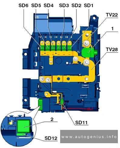
Fuse box diagram (relay/fuse holder F -SF-)
Audi A1 (8X; 2010 – 2018) – fuse and relay box diagram – passenger compartment (holder F)
Fuse/Relay panel under the steering wheel
No.
A
Function/component
1
40
Voltage stabiliser -J532-
2
50
Supply
fuse carrier 1 -ST1- in fuse holder D -SD-
3
40
Terminal 15 voltage supply relay -J329-
4
40
ABS control unit -J104-
5
5
Voltage stabiliser 2 -J570-, gradual phase-out
6
5
Onboard supply control unit -J519-
Voltage stabiliser -J532-
Voltage stabiliser 2 -J570-, gradual phase-out
Engine control unit -J623-
16
10
Brake light switch -F- (from November 2011, up to October 2014)
Clutch position sender -G476- (from November 2011, up to November 2014)
17
5
Lambda probe heater -Z19- (from November 2011, up to October 2014)
Lambda probe 1 heater after catalytic converter -Z29- (from November 2011, up to November 2014)
WARNING: Terminal and harness assignments for individual connectors will vary depending on vehicle equipment level, model, and market.
Year of production: 2013, 2014, 2015, 2016, 2917, 2018
This article covers the second-generation MG MG3, following its first facelift, produced from 2013 to 2018. It includes fuse box diagrams for the 2013 to 2018 models, provides information on the locations of the fuse panels inside the vehicle, and details the function of each fuse (fuse layout).
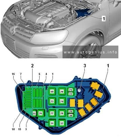
Year of production: 2010, 2011, 2012, 2013, 2014, 2015, 2016, 2017, 2018
This article provides the second-generation Volkswagen Touareg (7P), manufactured between 2010 and 2018. It provides fuse box diagrams for the Volkswagen Touareg models from 2011 to 2018, along with details on the location of the fuse panels within the vehicle. Additionally, you’ll find information on the fuse layout and the functions of each fuse and relay.
Fuse assignment in fuse box, right-side instrument panel
Assignment of the fuses in the right-side of the instrument panel
No.
А
Function/component
1
–
Not assigned
2
15
Adaptive suspension control unit -J197-
3
10
Axle differential lock control unit -J647-
4
30
Axle differential lock control unit -J647-
5
25
156
Trailer detector control unit -J345-
6
15
Trailer detector control unit -J345-
7
15
256
Trailer detector control unit -J345-
8
15
256
Trailer detector control unit -J345-
9
30
Rear right door control unit -J389-
10
–
Not assigned
11
30
Front passenger door control unit -J387-
12
–
Not assigned
13
15
Trailer detector control unit -J345-6
14
10
Airbag control unit -J234-
Front passenger airbag deactivated warning lamp -K145-
Seat occupied recognition control unit -J706-3
15
10
Transfer box control unit -J646-
16
5
Control unit for electromechanical parking brake -J540-
Operating unit to regulate suspension height -E281-
Left washer jet heater element -Z20-
Right washer jet heater element -Z21-
Button for TCS and electronic stabilisation program -E256-
ABS control unit -J104-
Hill descent control button -E618-
Electromechanical parking brake button -E538-
Auto-hold button -E540-6
Voltage stabiliser -J532-2
17
15
Front right headlight -MX2-
18
30
Igniter for front passenger side seat belt tensioner 2 -N298-
19
5
Tiptronic switch -F189-
Multifunction switch -F125-
Automatic gearbox control unit -J217-
20
25
Front passenger seat position control unit -J720-1
Valve block 1 in front passenger seat -N477-1
Control unit for front passenger multicontour seat -J872-1
Control unit for front right seat ventilation -J799-1
Front passenger seat rake adjustment button -E334-1
Front passenger seat longitudinal adjustment switch -E64-1
Front passenger side height adjustment switch -E290-1
Front passenger seat backrest adjustment switch -E98-1
Front passenger seat lumbar support adjustment switch -E177-1
21
25
Heated rear seats control unit -J786-1
Operating and display unit for rear air conditioning system -E265-1
22
–
Not assigned
23
25
Rear lid control unit -J605-
24
10
Climatronic control unit -J255-
Operating and display unit for rear air conditioning system -E265-1
25
5
Control unit for overhead view camera -J928-
Reversing camera system control unit -J772-
26
30
Heated rear window relay -J9-
27
5
Remote control receiver for auxiliary coolant heater -R149-
28
20
Gearbox hydraulic pump relay -J510-
Transfer box control unit -J646-
Automatic gearbox control unit -J217-
28
55
206
Transfer box control unit -J646-
29
30
ABS control unit -J104-
30
5
Tiptronic switch -F189-5
31
306,7
205
Convenience system central control unit -J393-
32
30
Rear fresh air blower -V80-4
33
30
Convenience system central control unit -J393-
34
–
Not assigned
35
5
Control unit for vehicle location system -J895-4
36
30
Convenience system central control unit -J393-
37
20
Automatic gearbox control unit -J217-5
Gearbox hydraulic pump relay -J510-5
38
15
Cigarette lighter -U1-
12 V socket 2 -U18-
Heated rear seats control unit -J786-
39
15
12 V socket 3 -U19-
12 V socket 4 -U20-
40
20
304
DC/AC converter with socket, 12 V – 230 V -U13-
41
10
Connection 2 for external audio sources -R231-5 Not assigned6
42
5
Trailer detector control unit -J345-
43
10
Axle differential lock control unit -J647-
44
5
Air quality sensor -G238-
45
30
Voltage stabiliser -J532-2
46
30
Voltage stabiliser -J532-2
47
10
Control unit 1 for information electronics -J794-
Display unit for front information display and operating unit control unit -J685-
48
30
Digital sound package control unit -J525-1
49
–
Not assigned
50
5
TV tuner -R78-1
Mobile telephone operating electronics control unit -J412-1
51
20
Radio -R-
52
5
Control unit in dash panel insert -J285-
53
5
DVD changer -R161-
54
5
Interface for external multimedia unit -R215-4
55
–
Not assigned
56
40
ABS control unit -J104-
57
40
Control unit for electromechanical parking brake -J540-
Transfer box control unit -J646-
1) According to equipment
2) Only models with start/stop system
3) Only for American markets
4) From November 2010
5) From November 2012
6) From August 2014
7) Up to November 2012
Fuse assignment in fuse box, left-side instrument panel
Radiator fan control unit -J293-
Automatic glow period control unit -J179-
Additional coolant pump relay -J496-
Brake light switch -F-
Exhaust gas recirculation cooler changeover valve -N345-
Exhaust gas recirculation cooling bypass valve -N386-
Valve for oil pressure control -N428-
Throttle valve module -J338-
Radiator fan control unit -J293-
Automatic glow period control unit -J179-
Additional coolant pump relay -J496-
Brake light switch -F-
Exhaust gas recirculation cooler changeover valve -N345-
Coolant valve for cylinder head -N489-
Valve for oil pressure control -N428-
Map-controlled engine cooling system thermostat -F265-
Right electrohydraulic engine mounting solenoid valve -N145-1
Radiator fan control unit -J293-
Automatic glow period control unit -J179-
Glow period control unit 2 -J703-
Additional coolant pump relay -J496-
Brake light switch -F-
Exhaust gas recirculation cooler changeover valve -N345-
Coolant valve for cylinder head -N489-
Valve for oil pressure control -N428-
Throttle valve module -J338-
11
15
Oil level and oil temperature sender -G266-
Heater element for crankcase breather -N79-
Heater element 2 for crankcase breather -N483-