Volkswagen Golf VII (mk7; 2013 – 2020) – fuse and relay box diagram
Year of production: 2013, 2014, 2015, 2016, 2017, 2018, 2019, 2020
Overview of fuse holder
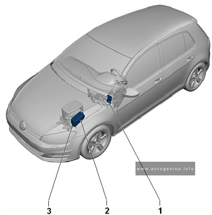
| № | Description |
|---|---|
| 1 | Fuse panel C -SC- |
| 2 | Fuse panel B -SB- |
| 3 | Fuse panel A -SA- |
Passenger Compartment Fuse Box
Fuse Box Diagram (Fuse Panel C- SC)
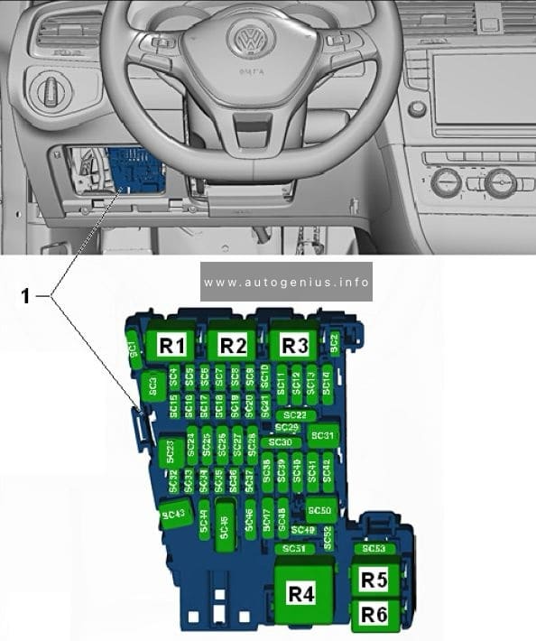
Fuse assignment fuse panel C -SC-
| № | Designation in Wiring Diagram | A | Component | Terminal |
|---|---|---|---|---|
| F1 | — | — | — | — |
| F2 | — | — | — | — |
| F3 | — | — | — | — |
| F4 | Fuse 4 on fuse panel C -SC4- | 10 | Vehicle electrical system control module -J519-, Anti-theft alarm system |
30 |
| F5 | Fuse 5 on fuse panel C -SC5- | 5 | Data bus on board diagnostic interface -J533- | 30 |
| F6 | Fuse 6 on fuse panel C -SC6- | 5 | Anti-theft alarm system sensor -G578- | 30 |
| F7 | Fuse 7 on fuse panel C -SC7- | 10 | Heater and A/C controls -EX21- Heater control module -J65- Climatronic control unit -J255- A/C control module -J301- Selector lever -E313- Auxiliary engine coolant heater radio frequency receiver -R149- Rear window defogger relay -J9- |
30 |
| F8 | Fuse 8 on fuse panel C -SC8- | 10 | Rotary light switch -EX1- 30 Electro-mechanical parking brake button -E538- Humidity, rain and light recognition sensor -G823- Diagnostic connection -U31- |
30 |
| F9 | — | — | — | — |
| F10 | Fuse 10 on fuse panel C -SC10- | 10 | Front information display control head -J685- | 30 |
| F11 | Fuse 11 on fuse panel B -SB11- | 15 | All wheel drive control module -J492- | 30 |
| F12 | Fuse 12 on fuse panel C -SC12- | 20 | Information electronics control module 1 -J794- | 30 |
| F13 | Fuse 13 on fuse panel C -SC13- | 15 | Electronic damping control module -J250- | 30 |
| F14 | Fuse 14 on fuse panel C -SC14- | 30 | Fresh air blower control module -J126- | 30 |
| F15 | Fuse 15 on fuse panel C -SC15- | 10 | Electronic steering column lock control module -J764- |
30 |
| F16 | Fuse 16 on fuse panel C -SC16- | 7,5 | Mobile communication 2-way signal amplifier -J984- Antenna amplifier 3 -R112- Voltage converter for USB charge module -A5- |
30 |
| F17 | Fuse 17 on fuse panel C -SC17- | 5 | Instrument cluster control module -J285- Instrument cluster -KX2- |
30 |
| F18 | Fuse 18 on fuse panel C -SC18- | 7,5 | Rearview camera -R189- Rear lid unlock switch -E165- |
30 |
| F19 | Fuse 19 on fuse panel C -SC19- | 7,5 | Access/start system interface -J965- | 30 |
| F20 | — | — | — | — |
| F21 | — | — | — | — |
| F22 | — | — | — | — |
| F23 | Fuse 23 on fuse panel C -SC23- | 40 | Vehicle electrical system control module -J519- Right front headlamp -MX2- |
30 |
| F24 | Fuse 24 on fuse panel C -SC24- | 30 | Power sunroof control module -J245- | 30 |
| F25 | Fuse 25 on fuse panel C -SC25- | 30 | Driver door control module -J386- 1) Left rear window regulator motor -V26- 1) Front passenger door control module -J387- 2) Right rear window regulator motor -V27- 2) |
30 |
| F26 | Fuse 26 on fuse panel C -SC26- | 20 | Vehicle electrical system control module -J519- Front heated seat |
30 |
| F27 | Fuse 27 on fuse panel C -SC27- | 30 | Digital Sound System Control Module -J525- | 30 |
| F28 | Fuse 28 on fuse panel C -SC28- | 20 | Towing recognition control module -J345- | 30 |
| F29 | — | — | — | — |
| F30 | Fuse 30 on fuse panel C -SC30- | 25 | Left front seat belt tensioner control module -J854- | 30 |
| F31 | Fuse 31 on fuse panel C -SC31- | 40 | Vehicle electrical system control module -J519- Left front headlamp -MX1- |
30 |
| F32 | Fuse 32 on fuse panel C -SC32- | 7,5 | Driver assistance systems front camera -R242- Distance regulation control module -J428- Parking aid control module -J446- Parallel parking assistance control module – J791- |
15 |
| F33 | Fuse 33 on fuse panel C -SC33- | 5 | Airbag control module -J234- | 15 |
| Front passenger airbag -disabled- indicator lamp -K145- |
||||
| F34 | Fuse 34 on fuse panel C -SC34- | 7,5 | Rotary light switch -EX1- Interior rearview mirror -EX5- Tire pressure monitoring display button -E492- Socket relay -J807- Back-up lamp switch -F4- Refrigerant circuit pressure sensor -G805- Air quality sensor -G238- Electro-mechanical parking brake button – E538- |
15 |
| F15 | Fuse 35 on fuse panel C -SC35- | 10 | Diagnostic connection -U31- Headlamp range control and instrument illumination regulator -EX14- Automatic dimming interior rearview mirror -Y7 – Cornering lamp and headlamp range control module -J745- Left headlamp beam adjustment motor -V48- Right headlamp beam adjustment motor -V49- |
15 |
| F36 | Fuse 36 on fuse panel C -SC36- | 10 | Right daytime running lamp and parking lamp control module -J861- |
15 |
| F37 | Fuse 37 on fuse panel C -SC37- | 10 | Left daytime running lamp and parking lamp control module -J860- |
15 |
| F38 | Fuse 38 on fuse panel C -SC38- | 20 | Towing recognition control module -J345- | 30 |
| F39 | Fuse 39 on fuse panel C -SC39- | 30 | Front passenger door control module -J387- Right rear window regulator motor -V27- 1) Driver door control module -J386- 2) Left rear window regulator motor -V26- 2) |
30 |
| F40 | Fuse 40 on fuse panel C -SC40- | 20 | Cigarette lighter -U1-3) 12 V socket -U5- 12 V socket 2 -U18- 12 V socket 3 -U19- |
15/30 4) |
| F41 | Fuse 41 on fuse panel C -SC41- | 10 | Steering column electronics control module -J527- | 30 |
| F42 | Fuse 42 on fuse panel C -SC42- | 40 | Vehicle electrical system control module -J519- Central locking system |
30 |
| F43 | Fuse 43 on fuse panel C -SC43- | 30 | Vehicle electrical system control module -J519- | 30 |
| F44 | Fuse 44 on fuse panel C -SC44- | 15 | Towing recognition control module -J345- | 30 |
| F45 | Fuse 45 on fuse panel C -SC45- | 15 | Driver seat lumbar support adjustment switch -E176- Driver seat adjustment control head -E470- Front passenger seat adjustment control head -E471- Front passenger seat lumbar support adjustment switch -E177- |
30 |
| F46 | — | — | — | — |
| F47 | Fuse 47 on fuse panel C -SC47- | 15 | Rear window wiper motor -V12- | 15 |
| F48 | — | — | — | — |
| F49 | Fuse 49 on fuse panel C -SC49- | 5 | Clutch pedal position sensor -G162- Starter relay 1 -J906- Starter relay 2 -J907- |
15 |
| F50 | — | — | — | — |
| F51 | Fuse 51 on fuse panel C -SC51- | 25 | Right front seat belt tensioner control module -J855- | 15 |
| F52 | — | — | — | — |
| F53 | — | — | — | — |
| 1) Only for left-hand drive vehicles 2) Only for right-hand drive vehicles 3) Smoking package 4) Depending on equipment |
||||
Engine Compartment Fuse Box
Fuse Box Diagram (Fuse Panel B- SB)
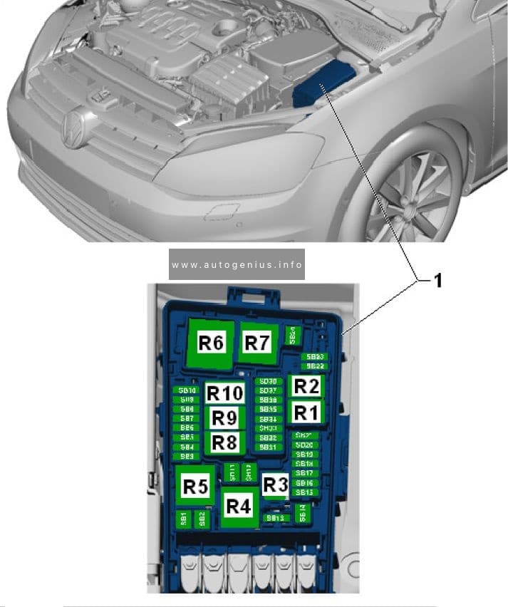
Fuse assignment fuse panel B -SB-
| № | Designation in Wiring Diagram | A | Component | Terminal |
| F1 | Fuse 1 on fuse panel B -SB1- | 40 | ABS control module -J104- | 30 |
| F2 | Fuse 2 on fuse panel B -SB2- | 40 | ABS control module -J104- ABS hydraulic pump -V64- |
30 |
| F3 | Fuse 3 on fuse panel B -SB3- | 15 1) | Engine control module -J623- | 87 |
| 30 2) | ||||
| F4 | Fuse 4 on fuse panel B -SB4- | 5 2) | Oil level thermal sensor -G266- 87 Coolant fan control module -J293- EVAP canister purge regulator valve 1 -N80- 1) Camshaft adjustment valve 1 -N205-(1 Exhaust camshaft adjustment valve 1 -N318- 1) Oil pressure regulation valve -N428- 1) High heat output relay -J360-2) EGR cooler switch-over valve -N345- 2) Low heat output relay -J359- 2) Wastegate bypass regulator valve -N75- 2) Cylinder 2 intake camshaft adjuster -N583- 1) Cylinder 2 exhaust camshaft adjuster -N587- 1) Cylinder 3 intake camshaft adjuster -N591- 1) Cylinder 3 exhaust camshaft adjuster -N595- 1) Ethanol concentration sensor -G708- 1) |
87 |
| 10 1) | ||||
| F5 | Fuse 5 on fuse panel B -SB5- | 10 2) | Fuel pressure regulator valve -N276- Fuel metering valve -N290- |
87 |
| F6 | Fuse 6 on fuse panel B -SB6- | 5 | Brake lamp switch -F- | 87 |
| F7 | Fuse 7 on fuse panel B -SB7- | 7,5 1) | Fuel pressure regulator valve -N276-1) Charge air cooling pump -V188-1) Oil pressure regulation valve -N428-2) Cooling circuit solenoid valve -N492-2) Charge air cooling pump -V188-2) Heater support pump -V488- 2) |
87 |
| 10 2) | ||||
| F8 | Fuse 8 on fuse panel B -SB8- | 10 1) | Oxygen sensor heater -Z19- Oxygen sensor 1 before catalytic converter -GX10- Heater for oxygen sensor 1 after catalytic converter -Z29- Oxygen sensor 1 after catalytic converter -GX7- Mass airflow sensor -G70- |
87 |
| F9 | Fuse 9 on fuse panel B -SB9- | 5 2) | Ignition coil 1 with power output stage -N70- 1) Ignition coil 2 with power output stage -N127-1) Ignition coil 3 with power output stage -N291- 1) Ignition coil 4 with power output stage -N292-1) Automatic glow time control module -J179- 2) Early fuel evaporation heating element -N51- 2) |
87 |
| 20 1) | ||||
| F10 | Fuse 10 on fuse panel B -SB10- | 15 1) | Fuel pump control module -J538- | 87 |
| 20 2) | ||||
| F11 | Fuse 11 on fuse panel B -SB11- | 40 | Auxiliary heater heating element -Z35- | 87 |
| F11 | Fuse 11 on fuse panel B -SB11- | 40 | Auxiliary heater heating element -Z35- | 87 |
| F12 | Fuse 12 on fuse panel B -SB12- | 40 | Auxiliary heater heating element -Z35- | 87 |
| F13 | Fuse 13 on fuse panel B -SB13- | 30 | DSG transmission Mechatronic -J743- | 30 |
| F14 | — | — | — | — |
| F15 | Fuse 15 on fuse panel B -SB15- | 15 | Horn relay -J413- | 30 |
| F16 | — | — | — | — |
| F17 | Fuse 17 on fuse panel B -SB17- | 7,5 | Motronic engine control module power supply relay -J271- 1) Terminal 30 power supply relay -J317-2) Engine control module -J623- ABS control module -J104- |
30 |
| F18 | Fuse 18 on fuse panel B -SB18- | 5 | Battery monitoring control module -J367- Data bus on board diagnostic interface -J533- 3) |
30 |
| F19 | Fuse 19 on fuse panel B -SB19- | 30 | Wiper motor control module -J400- | 30 |
| F20 | Fuse 20 on fuse panel B -SB20- | 20 | Anti-theft alarm system horn -H8- | 30 |
| F21 | — | — | — | — |
| F22 | Fuse 22 on fuse panel B -SB22- | 5 | Engine control module -J623- | 50 |
| F23 | Fuse 23 on fuse panel B -SB23- | 30 | Starter -B- | 50 |
| F24 | Fuse 24 on fuse panel B -SB24- | 40 | Auxiliary heater heating element -Z35- | 87 |
| F25 | — | — | — | — |
| F26 | — | — | — | — |
| F27 | — | — | — | — |
| F28 | — | — | — | — |
| F29 | — | — | — | — |
| F30 | — | — | — | — |
| F31 | — | — | — | — |
| F32 | — | — | — | — |
| F33 | — | — | — | — |
| F34 | — | — | — | — |
| F35 | — | — | — | — |
| F36 | — | — | — | — |
| F37 | Fuse 37 on fuse panel B -SB37- | 20 | Auxiliary heater control module -J364- | 30 |
| F38 | — | — | — | — |
| 1) Only for vehicles with gasoline engine 2) only for vehicles with a diesel engine 3) Only for vehicles without Stop/Start |
||||
Engine Compartment Fuse Box
Fuse Box Diagram (Fuse Panel A- SA)
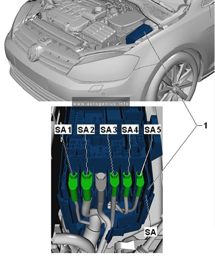
Fuse assignment fuse panel A -SA-
| № | Designation in Wiring Diagram | A | Component | Terminal |
|---|---|---|---|---|
| J | Fuse 1 on fuse panel A -SA1- | 100 | Fuses Supply: -SC4- …-SC14- -SC30- -SC31- -SC38- -SC39- -SC41- -SC42- -SC53- Front passenger power seat adjustment circuit breaker 1 -S46- Terminal 15 power supply relay -J329- |
30 |
| G1 | Fuse 2 on fuse panel A -SA2- | 100 1) | Generator -C- | 30 |
| 200 2) | ||||
| 250 3) | ||||
| E1 | Fuse 3 on fuse panel A -SA3- | 80 | Power steering control module -J500- | 30 |
| K1 | Fuse 4 on fuse panel A -SA4- | 80 | Fuses Supply: -SC15- …-SC20- -SC23- …-SC28- -SB43- …-SB45- |
30 |
| L1 | Fuse 5 on fuse panel A -SA5- | 80 | Coolant fan -VX57- | 30 |
| 1) Only for vehicles with a 90 A generator 2) Only for vehicles with a 140 A generator 3) Only for vehicles with a 180 A generator |
||||
WARNING: Terminal and harness assignments for individual connectors will vary depending on vehicle equipment level, model, and market.