Toyota Previa (2013 – 2015) – fuse and relay box diagram
Year of production: 2013, 2014, 2015
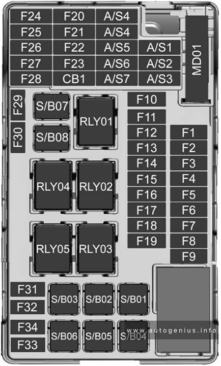
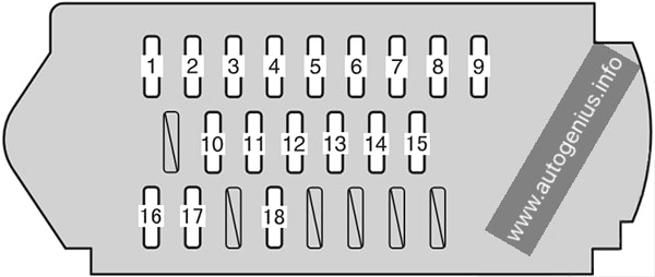
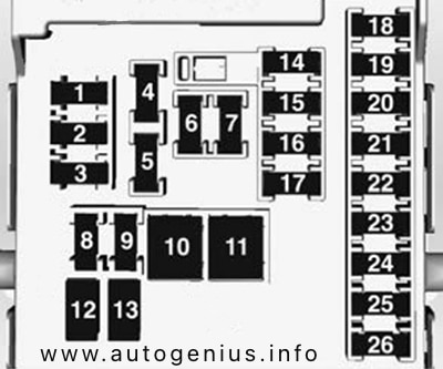
Instrument Panel Fuse Box №1 (left side)
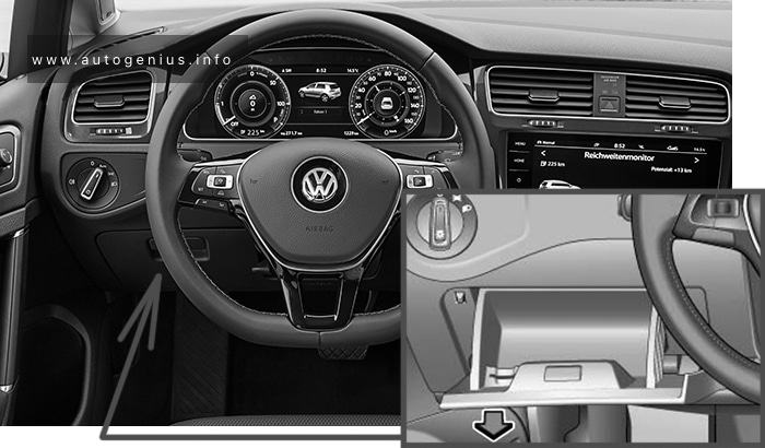
Fuse Box Location
Remove the cover; Remove the lid.
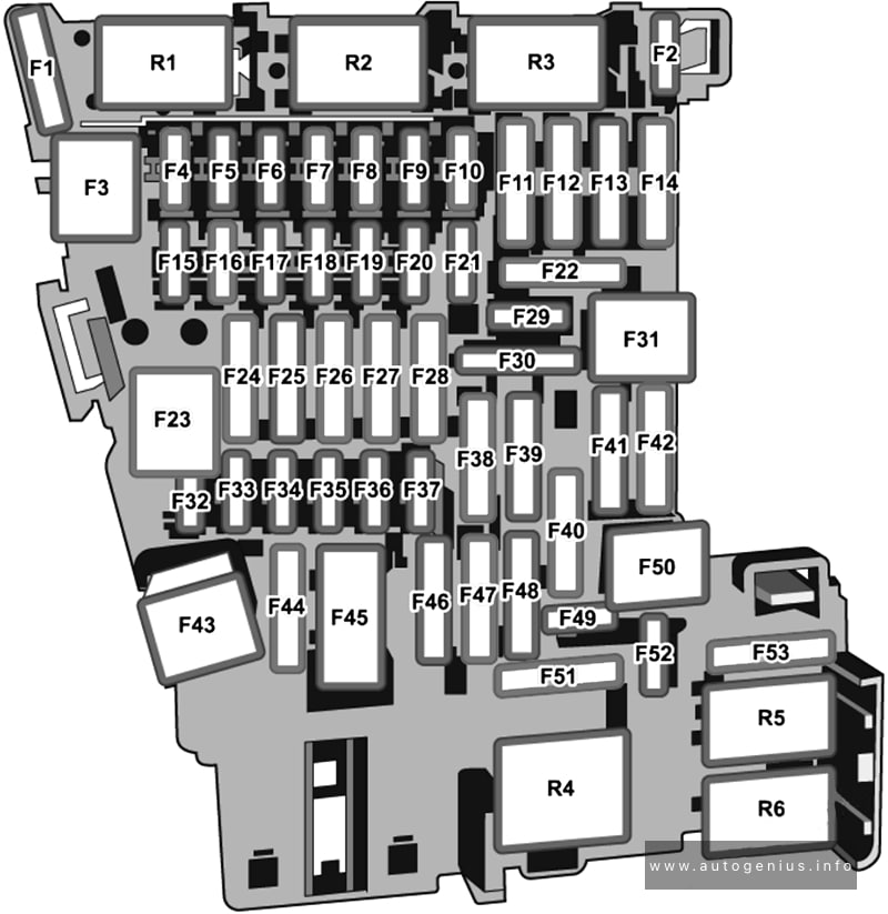
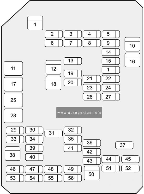
Fuse Box Diagram
Assignment of the fuses in the Fuse Box №1
| № | Name | Amp | Description |
|---|---|---|---|
| 1 | WELCAB | 30A | No circuit |
| 2 | 4WD | 7.5A | No circuit |
| 3 | AC INV | 15A | No circuit |
| 4 | DR LOCK | 30A | Smart entry & start system, pushbutton start system, multiplex communication system |
| 5 | P/W FL | 20A | Power windows |
| 6 | S/R | 20A | Rear sunshade |
| 7 | PSD LH | 30A | Power sliding doors |
| 8 | P/W RL | 20A | Power windows |
| 9 | PBD | 30A | No circuit |
| 10 | RR WIP | 15A | Windshield wipers and washer, rear window wiper and washer, headlight cleaners |
| 11 | GAUGE №1 | 10A | Anti-lock brake system, vehicle stability control, adaptive frontlighting system, electric cooling fans, Toyota parking assist-sensor, headlight cleaners |
| 12 | PANEL | 10A | Instrument panel lights, Toyota parking assist-sensor |
| 13 | TAIL | 10A | Front fog lights, tail lights, front position lights, license plate lights |
| 14 | LH ECU-IG | 10A | Adaptive front-lighting system, multiplex communication system, smart entry & start system, pushbutton start system, power sliding doors, power seat (third seats) |
| 15 | SEAT HTR LH | 10A | Seat heater LH |
| 16 | GAUGE №2 | 10A | Charging system, automatic transmission system / continuously variable transmission system, back-up lights, Toyota parking assist-sensor, power seat (third seats) |
| 17 | STP RR | 7.5A | No circuit |
| 18 | STP HI MT | 7.5A | No circuit |
| 19 | STP RL | 7.5A | No circuit |
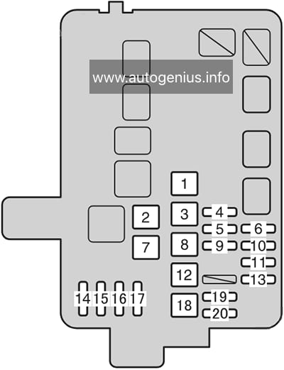
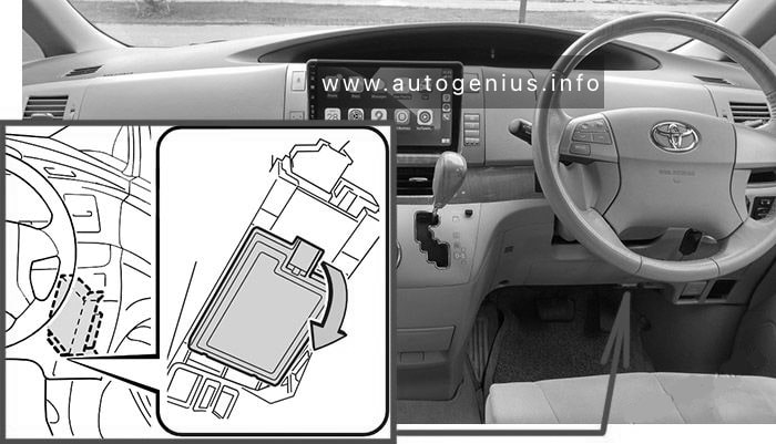
Instrument Panel Fuse Box №2 (right side)
Fuse Box Location
Remove the lid.

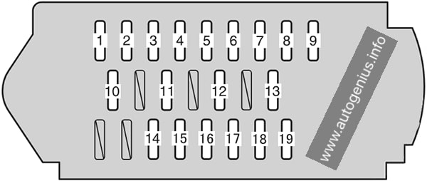
Fuse Box Diagram

Assignment of the fuses in the Fuse Box №2
| № | Name | Amp | Description |
|---|---|---|---|
| 1 | PSB | 30A | No circuit |
| 2 | RR FOG | 7.5A | No circuit |
| 3 | P/W FR | 20A | Power windows |
| 4 | P/SEAT RH | 30A | Power seat (Front seat) |
| 5 | AM1 | 7.5A | No circuit |
| 6 | STOP | 15A | Stop lights, high mounted stoplight, automatic transmission system / continuously variable transmission system, shift lock system, multiport fuel injection system / sequential multiport fuel injection system, anti-lock brake system, vehicle stability control |
| 7 | OBD | 7.5A | On-board diagnosis system |
| 8 | PSD RH | 30A | Power sliding doors |
| 9 | P/W RR | 20A | Power windows |
| 10 | P/POINT | 15A | Power outlet |
| 11 | P/POINT №2 | 15A | Power outlet |
| 12 | RAD №2 | 7.5A | Audio system, rear seat entertainment system |
| 13 | ECU-ACC | 7.5A | Smart entry & start system, pushbutton start system, outside rear view mirrors, shift lock system |
| 14 | IGN | 10A | Multiport fuel injection system / sequential multiport fuel injection system, SRS airbag system, multiplex communication system |
| 15 | MET | 7.5A | Gauges and meters |
| 16 | FR WIP | 30A | Windshield wipers and washer |
| 17 | SEAT HTR RH | 10A | Seat heater RH |
| 18 | RH ECU-IG | 10A | Vehicle stability control, air conditioning system, Toyota parking assist sensor, automatic transmission system / continuously variable transmission system, electric power steering, smart entry & start system, push-button start system, power sliding doors, rear sunshade, shift lock system, turn signal lights, emergency flashers, vanity lights, multiplex communication system |
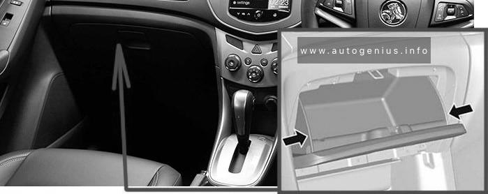
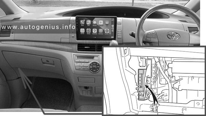
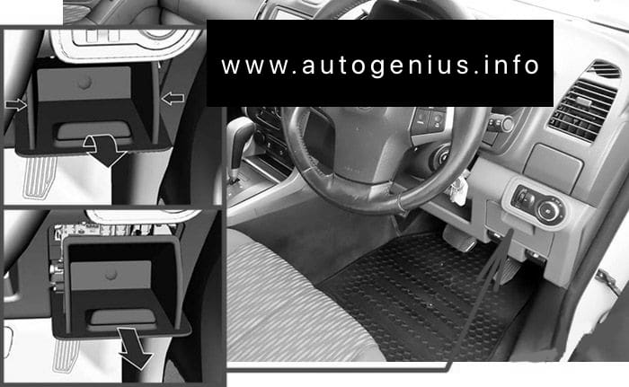
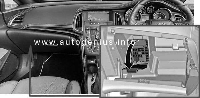
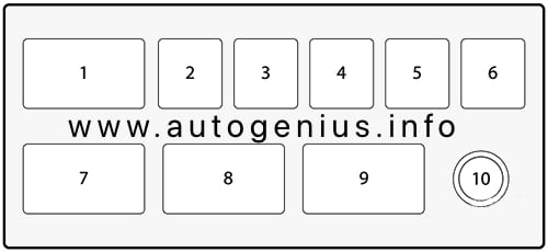
Instrument Panel Fuse Box №3
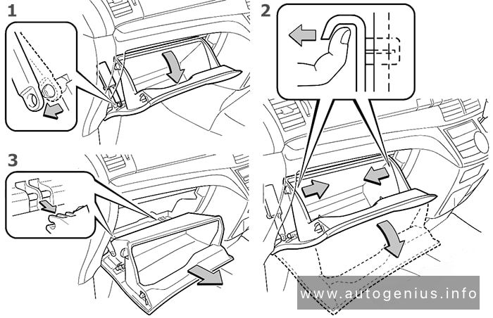
Fuse Box Location
Remove the lid.

To access:
- Open the glove box. Slide off the damper.
- Pull both side of the glove box from the inside to disconnect the upper claws.
- Pull out the glove box and disconnect the lower claws.
Fuse Box Diagram

Assignment of the fuses in the Fuse Box №3
| № | Name | Amp | Description |
|---|---|---|---|
| 1 | HTR | 50A | Air conditioning system |
| 2 | 3RD SEAT RH | 30A | Power seat (Third seats) |
| 3 | 3RD SEAT LH | 30A | Power seat (Third seats) |
| 4 | RR A/C | 30A | Air conditioning system |
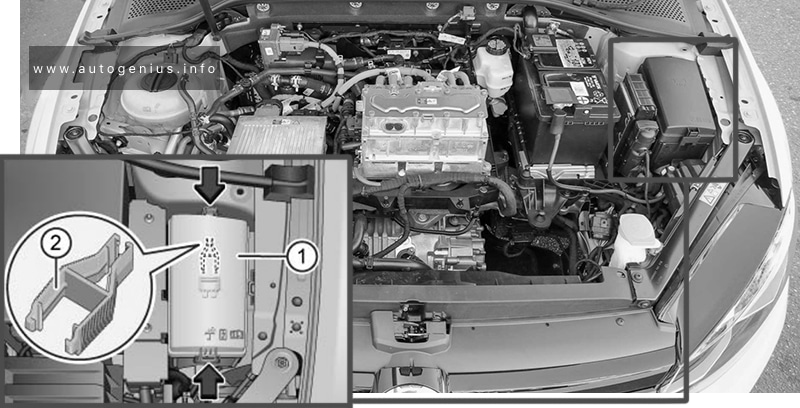
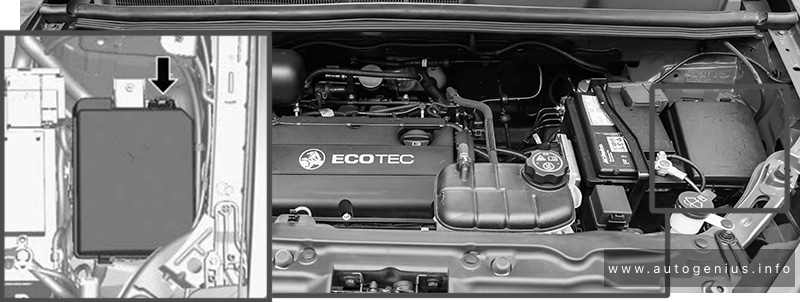
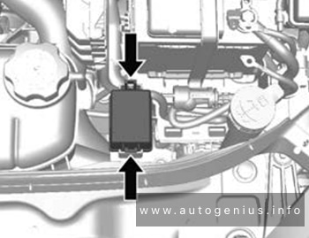
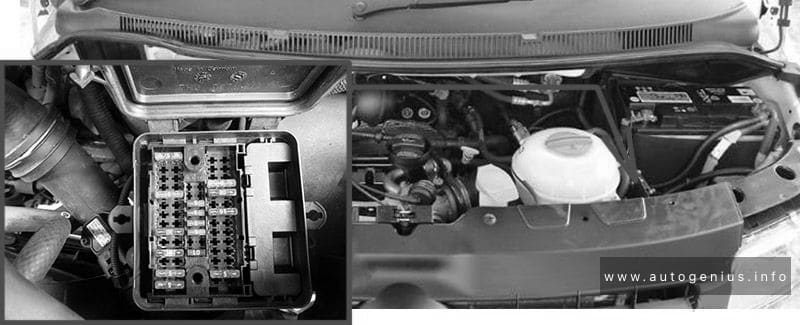
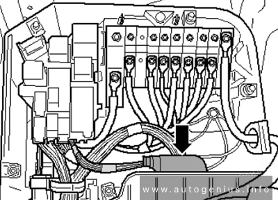
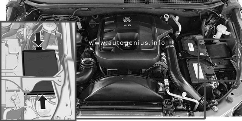
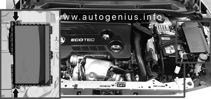
Engine Compartment
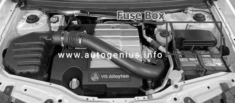
Fuse Box Location
Push the tab in and lift the lid off.
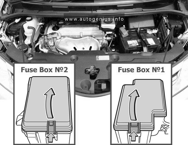
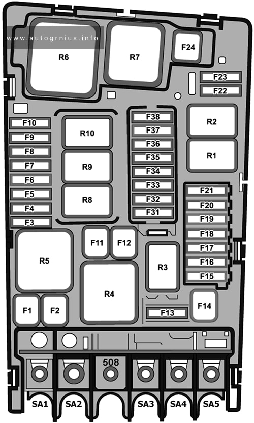
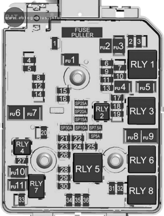
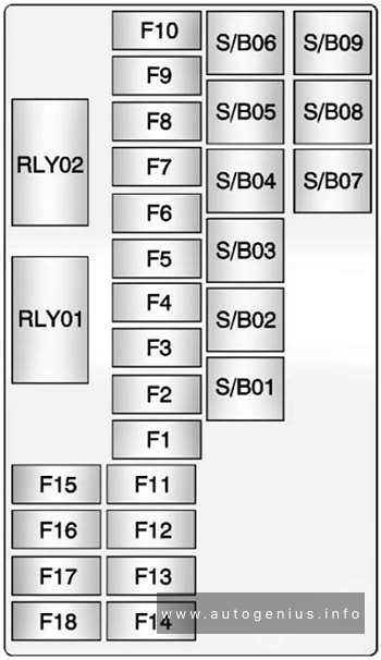
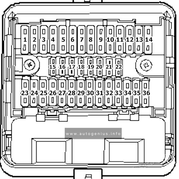
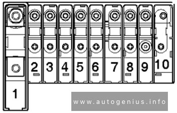
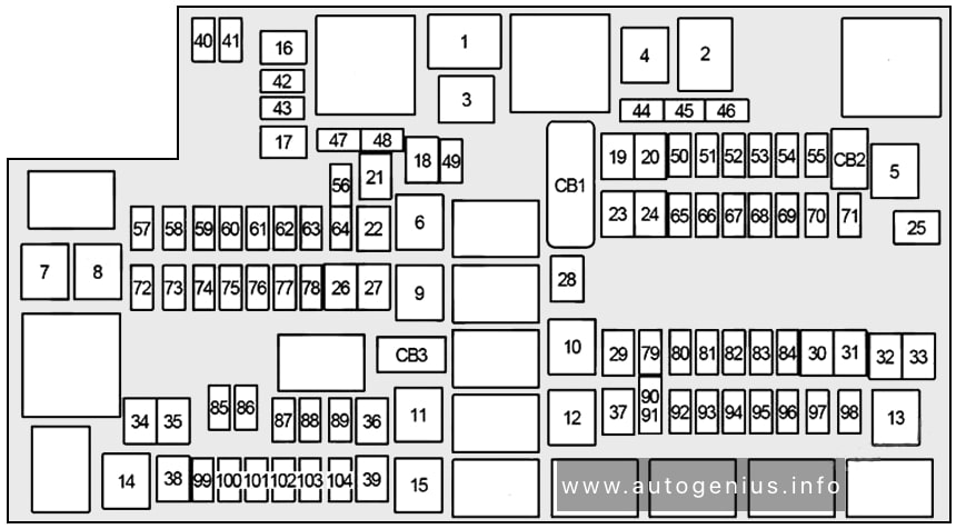
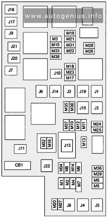
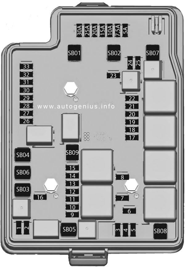
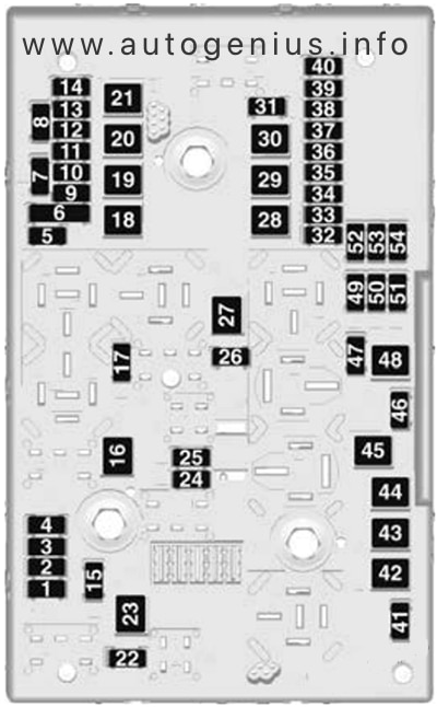
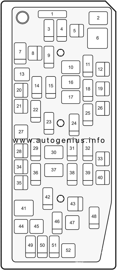
Fuse Box №1 Diagrams
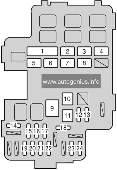
Assignment of the fuses in the Engine Compartment Fuse Box №1
| № | Name | Amp | Description |
|---|---|---|---|
| 1 | RH R/B ALT | 100A | CDS FAN, RDI FAN, PTC №1, PTC №2, PTC №3, H-LP CLAN, FOG fuse |
| 2 | RH-MAIN-JB | 60A | STOP, AM1, STP HI MT, STP RR, STP RL, OBD, P/W RR, PSB, P/ W FR, RR FOG, P/SEAT RH, PSD RH, CIG ECU-ACC, RAD №2, P/POINT, FR WIP, SEAT HTR RH, RH ECU-IG fuse |
| 3 | LH-MAIN-JB | 80A | TAIL, PANEL, P/W RL, PSD LH, S/R, 4WD, PBD, P/W FL, DR LOCK, GAUGE №1, RR WIP, SEAT HTR LH, GAUGE №2, LH ECU-IG, WASH fuse |
| 4 | SUB R/B | 80A | HTR. RR A/C, 3RD SEAT RH, 3RD SEAT LH fuse |
| 5 | F/B ALT | 100A | ABS №1, ABS №2, DEF fuse |
| 6 | ALT | 140A | Gauges and meters, charging system, F/B ALT, SUB R/B, RH-MAIN-JB, LH-MAIN-JB, RH R/B ALT fuse |
| 7 | F/B BATT | 120A | EPS, ST, A/F, EFI, TRN HAZ, IG2, FR DOOR, ETC-S, AM2 №2, AM2 N0.1, DOME, ECU-B, RAD №1 fuse |
| 8 | RH R/B BATT | 60A | Headlight cleaners, H-LP RL, H-LP LL, S/HORN, ECU-B3, ECU-B2, AMP, STRG LCK, HORN, H-LP RH, H-LP LH fuse |
| 9 | EPS | 80A | Electric power steering |
| 10 | ST | 30A | Multiport fuel injection system / sequential multiport fuel injection system, smart entry & start system, push-button start system |
| 11 | ABS №1 | 50A | Anti-lock brake system, vehicle stability control |
| 12 | ABS №2 | 30A | Anti-lock brake system, vehicle stability control |
| 13 | DEF | 25A | Rear window defogger, MIR HTR |
| 14 | EFI | 20A | Multiport fuel injection system / sequential multiport fuel injection system |
| 15 | ECU-B | 10A | Gauges and meters, air conditioning system, smart entry & start system, push-button start system, power sliding doors, multiplex communication system, wireless remote control system |
| 16 | DOME | 7.5A | Interior lights, luggage compartment light, door courtesy lights, front personal lights, rear personal lights, multiplex communication system |
| 17 | RAD №1 | 15A | Audio system, rear seat entertainment system |
| 18 | MIR HTR | 10A | No circuit |
| 19 | ETC-S | 10A | Multiport fuel injection system / sequential multiport fuel injection system |
| 20 | AM2 №2 | 7.5A | Multiport fuel injection system / sequential multiport fuel injection system, smart entry & start system, push-button start system |
| 21 | TRN HAZ | 15A | Turn signal lights, emergency flashers |
| 22 | IG2 | 15A | Multiport fuel injection system / sequential multiport fuel injection system, smart entry & start system, push-button start system, starting system, MET, IGN fuse |
| 23 | FR DOOR | 30A | Smart entry & start system, pushbutton start system, multiplex communication system |
| 24 | A/F | 30A | Multiport fuel injection system / sequential multiport fuel injection system |
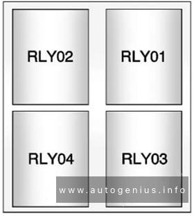
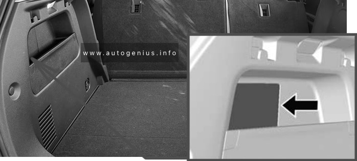
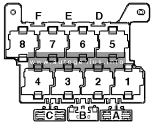
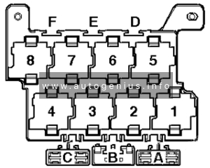
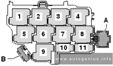
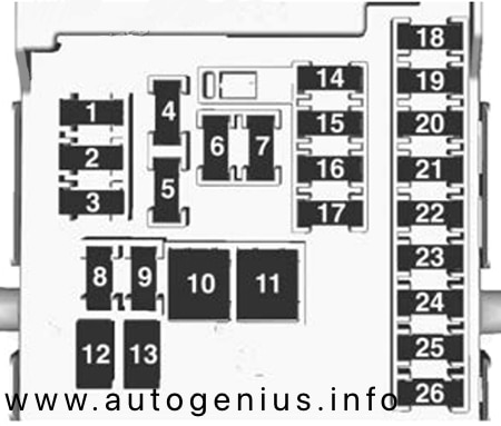
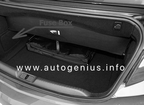
Engine Compartment Fuse Box №2
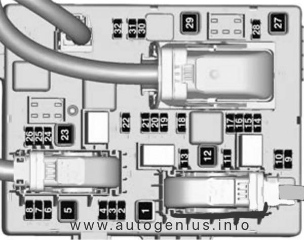
Fuse Box Diagrams

Assignment of the fuses in the Engine Compartment Fuse Box №2
| № | Name | Amp | Description |
|---|---|---|---|
| 1 | WEL CAB | 30A | No circuit |
| 2 | CDS FAN | 50A | 2AZ-FE engine: Electric cooling fans |
| RDI FAN №2 | 50A | 2GR-FE engine: Electric cooling fans | |
| 3 | H-LP CLN | 30A | Headlight cleaners |
| 4 | ECU-B3 | 7.5A | Smart entry & start system, pushbutton start system |
| 5 | ECU-B2 | 7.5A | Power windows |
| 6 | HORN | 10A | Horns |
| 7 | RDI FAN | 50A | 2AZ-FE engine: Electric cooling fans |
| RDI FAN №1 | 50A | 2GR-FE engine: Electric cooling fans | |
| 8 | PTC №3 | 50A | Air conditioning system |
| 9 | S/HORN | 10A | Smart entry & start system |
| 10 | STRG LCK | 20A | Smart entry & start system, pushbutton start system, steering lock system |
| 11 | AMP2 | 30A | No circuit |
| 12 | PTC №2 | 50A | Air conditioning system |
| 13 | AMP1 | 30A | No circuit |
| 14 | H-LP LH | 15A | Left-hand headlight (high beam) |
| 15 | H-LP RH | 15A | Right-hand headlight (high beam) |
| 16 | H-LP LL | 15A | Left-hand headlight (low beam) |
| 17 | H-LP RL | 15A | Headlight leveling system, right-hand headlight (low beam) |
| 18 | PTC №1 | 50A | Air conditioning system |
| 19 | DEICER | 20A | No circuit |
| 20 | FOG | 15A | Front fog lights |
WARNING: Terminal and harness assignments for individual connectors will vary depending on vehicle equipment level, model, and market.