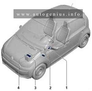
Volkswagen Jetta (A6; 2010 – 2017) – fuse and relay box diagram
Year of production: 2010, 2011, 2012, 2013, 2014, 2015, 2016, 2017
This article covers the sixth-generation Volkswagen Jetta (A6, Typ 1B), produced from 2010 to 2017. It provides fuse box diagrams for the 2010, 2011, 2012, 2013, 2014, 2015, 2016, and 2017 models, details the locations of the fuse panels inside the vehicle, and explains the function of each fuse (fuse layout) and relay.
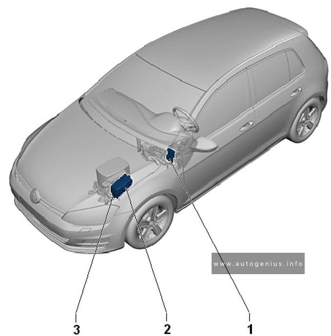
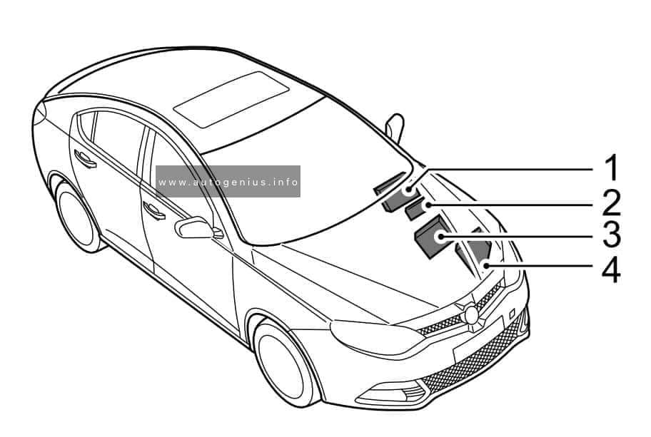
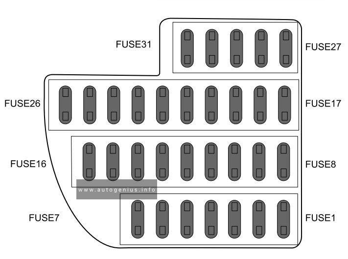
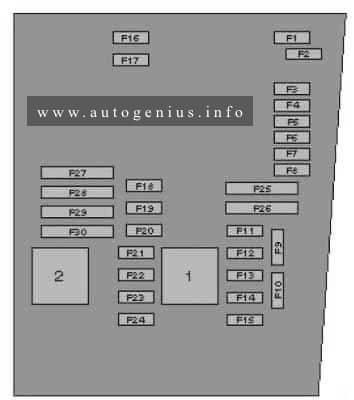
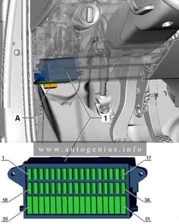
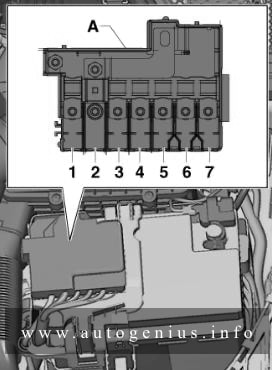
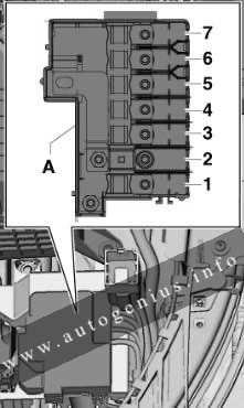
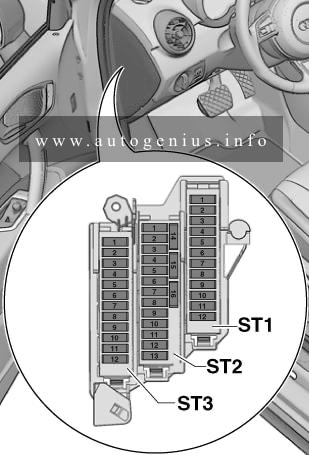
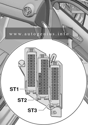
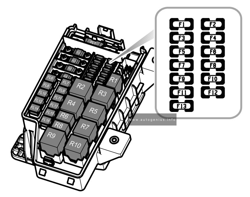
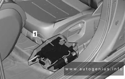
Passenger Compartment Fuse Box
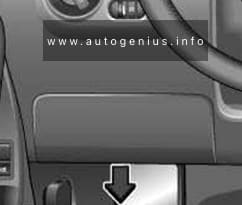
Fuse Box Location
The fuse box is located behind the cover on the driver’s side. Pull the lower part of the cover in the direction of the arrow and remove the cover from the bottom. On the inside of the cover there are plastic tweezers for removing and inserting fuses.
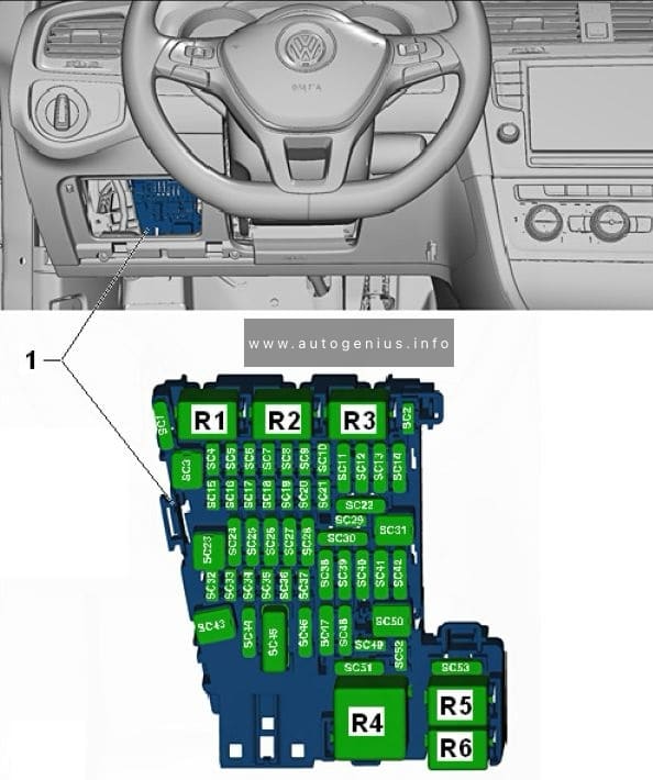
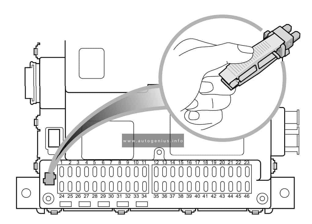
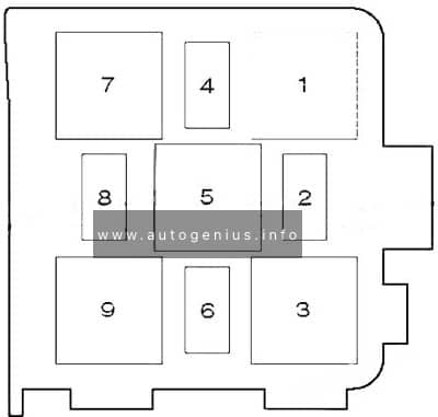
Fuse Box Diagram (-SC-)
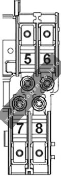
Assignment of the fuses in the instrument panel (holder C)
| № | Amps | Function/Component |
|---|---|---|
| F1 | 10A | 2014-2017: Left washer nozzle heater Right washer nozzle heater |
| F2 | 5A/7,5A | Electronic steering column lock control module |
| F3 | 10A | Instrument cluster control module |
| F4 | 2A/10A | 2012-2017: Telephone Transceiver Compass magnetic field sensor (vehicles equipped with Start/Stop) |
| F5 | 7.5A | 2012-2017: Left rear fog lamp bulb |
| F6 | 10A | Vehicle electrical system control module (T73a/66) (interior lamp, AW0 only) Rearview camera (2014-2017) |
| F7 | 5A | Fog lamp relay (AW0 only) Instrument panel and switch illumination dimmer switch (AW0 only) License plate lamp Vehicle electrical system control module (T52c/27), (AW1 only) |
| F8 | 7.5A | Windshield and headlamp washer pump switch (AW0 only) Windshield washer pump (AW0 only) Vehicle electrical system control module (T73b/61), (AW0 only) |
| F8 | – | not used (AW1 only) |
| F9 | 5A/15A | Arbag control module Airbag Control Module Front passenger airbag “disabled” indicator lamp Passenger occupant detection system control module |
| F10 | 10A | Right steering column switch (T10ls/3) (AW0 only) |
| F11 | 10A | 2012-2017: Left front headlamp (HID headlamp) |
| F12 | 10A | 2012-2017: Right front headlamp (HID headlamp) |
| F13 | 5A | Automatic dimming interior rearview mirror Light recognition sensor Parking aid control module Ar quality sensor High pressure sensor Climatronic control module Tire pressure monitoring button ASR/ESP button Back-up lamp switch Start/Stop mode switch 28-pin connector (T28/10) Mirror adjusting switch Exterior rearview mirror heating switch AC compressor control module (T14hy/14) (Engine code CNLA) Cornering lamp and headlamp range control module |
| F14 | 10A | Left steering column switch (T16ls/1) (AW0 only) ABS control module T26/20 / T47/8 Light switch (T10h/4) (AW1 only) Arbag spiral spring/return spring with slip ring (T16k/14) Fuel pump control module Towing recognition control module (T12a/2) Voltage stabilizer Converter with socket, 12V-230V (T3wr/3) Data bus on board diagnostic interface (AW1 only) Instrument cluster control module Selector lever sensor system control module Tiptronic switch (T10s/9) Power steering control module (T6z/1) Oil level thermal sensor (T6z/4) Hybrid battery unit (T14ax/7) (Engine code CNLA) Electric drive power and control electronics (T28jx/56) (Engine code CNLA) |
| F15 | 10A | 16-pin connector (diagnostic connection) Instrument panel and switch illumination dimmer switch Headlamp range control adjuster (AW1 only) Fresh air blower relay Mass airflow sensor Positive crankcase ventilation heating element – Structure borne sound control module Left front headlamp Left headlamp beam adjustment motor Right front headlamp Right headlamp beam adjustment motor Vehicle electrical system control module (T73a/44) |
| F16 | 10A | Auxiliary engine coolant pump relay Fuel pump control module Engine control module Electric drive button (Engine code CNLA) |
| F17 | 10A | 2012-2017: Anti-theft alarm system horn (Running change) Anti-theft alarm system interior sensor (Running change) Anti-theft alarm system alarm (Running change) |
| F18 | 15A | Left front headlamp Left low beam headlamp bulb (vehicles with China equipment) |
| F19 | 15A | Right front headlamp Right low beam headlamp bulb (vehicles with China equipment) |
| F20 | 10A | Ignition/starter switch (T10/10) (AW0 only) Tiptronic switch Automatic transmission control module Selector lever sensor system control module Climatronic control module Auxiliary engine coolant heater radio frequency receiver |
| F21 | 15A/20A | 2012-2017: Vehicle electrical system control module (T73a/73), (AW0 only) Dual tone horn relay (AW1 only) High tone horn (AW1 only) Low tone horn (AW1 only) |
| F22 | 20A/10A/7.5A | Ignition/starter switch (AW0 only) Converter box (AW0 only) Interior monitoring sensor Aarm horn relay Aarm horn Dual tone horn relay (2010-1011) |
| F23 | 10A | Vehicle electrical system control module (T73b/39) (AW0 only) 16-pin connector (diagnostic connection) Light switch (AW1 only) Rain/light recognition sensor Compass magnetic field sensor (vehicles without Start/Stop) |
| F24 | 10A | Vehicle electrical system control module (T73a/64) (AW0 only) Access/start authorization control module |
| F25 | 15A | Automatic transmission control module Selector lever sensor system control module Multifunction switch |
| F26 | 15A | Brake system vacuum pump |
| F27 | 1A | 2012-2017: Arbag spiral spring/return spring with slip ring (T16k/1) |
| F28 | 40A | Auxiliary heater operation relay |
| F29 | 1A | Vehicle electrical system control module (T73b/51) (AW0 only) Ignition/starter switch (AW0 only) Converter box (AW0 only) |
| F30 | 20A | Cigarette lighter 12V socket 12V socket 2 Blocking diode |
| F31 | 30A | Light switch (T17/1) (AW0 only) |
| F32 | 20A | Light switch (T17/2) (AW0 only) |
| F33 | 40A | Heater/heat output switch Fresh air blower relay AC control module Fresh air blower switch |
| F34 | 15A | Left high beam headlamp bulb (AW0 only) Right high beam headlamp bulb (AW0 only) Instrument cluster control module (AW0 only) |
| F35 | 10A | Steering column electronics control module (AW1 only) Data bus on board diagnostic interface (AW1 only) Instrument cluster control module (2010-2011) Signal horn activation (2010-2012) |
| F36 | 25A | Vehicle electrical system control module (T73a/16) (AW0 only) (T52b/1) (AW1 only) Vehicle electrical system control module (T73a/61) (AW0 only) (Running change) |
| F37 | 15A | Left front headlamp Left daytime running lamp bulb |
| F38 | 15A | Right front headlamp Right daytime running lamp bulb |
| F39 | 20A | Low beam relay |
| F40 | 15A | Towing recognition control module (T12a/9) |
| F41 | 15A | Towing recognition control module (T12a/12) |
| F42 | 20A | Towing recognition control module (T12a/11) |
| F43 | 30A | Front passenger door control module |
| F44 | 25A/30A | Rear window defogger relay (AW1 only) Rear window defogger Vehicle electrical system control module (T73b/67) (AW0 only) |
| F45 | 30A | Driver door control module Front passenger door control module (vehicles with China equipment) |
| F46 | 30A | Left rear door control module Right rear door control module |
| F47 | 15A | Fuel pump control module Fuel pump relay Fuel primer relay |
| F48 | 20A | Vehicle electrical system control module |
| F49 | 40A | Fresh air blower Climatronic control module A/C control module |
| F50 | 30A | Front seat heating control module |
| F51 | 20A | Sunroof control module |
| F52 | 20A | 2010-2012: Dual tone horn relay 2013-2017: Headlamp Washer Relay Headlamp washer pump |
| F53 | 15A | 2010-2012: Front seat heating control module 2013-2017: Driver seat lumbar support adjustment switch |
| F54 | 15A | Fog lamp relay |
| F55 | 20A | Light switch (T17/15) (AW0 only) Left steering column switch (T16ls/10) (AW0 only) |
| F56 | 10A | 2013-2017: Hybrid battery unit (T14ax/5) (Engine code CNLA) Electric drive power and control electronics (T28jx/55) (Engine code CNLA) |
| F57 | 15A/25A | Radio Radio/Navigation Display Control Module |
| F58 | 1A/30A | Telephone Transceaver (2010-2011) Converter with socket 12V-230V |
| F59 | 15A/30A | 2010-2012: Amplifier 2013-2017: Fan activation relay (Engine code CNLA) Battery fan 1 (Engine code CNLA) |
| F60 | 30A | Auxiliary heater control module |
| – | 20A | Driver power seat adjustment circuit breaker 1 (it is located above relay carrier) |
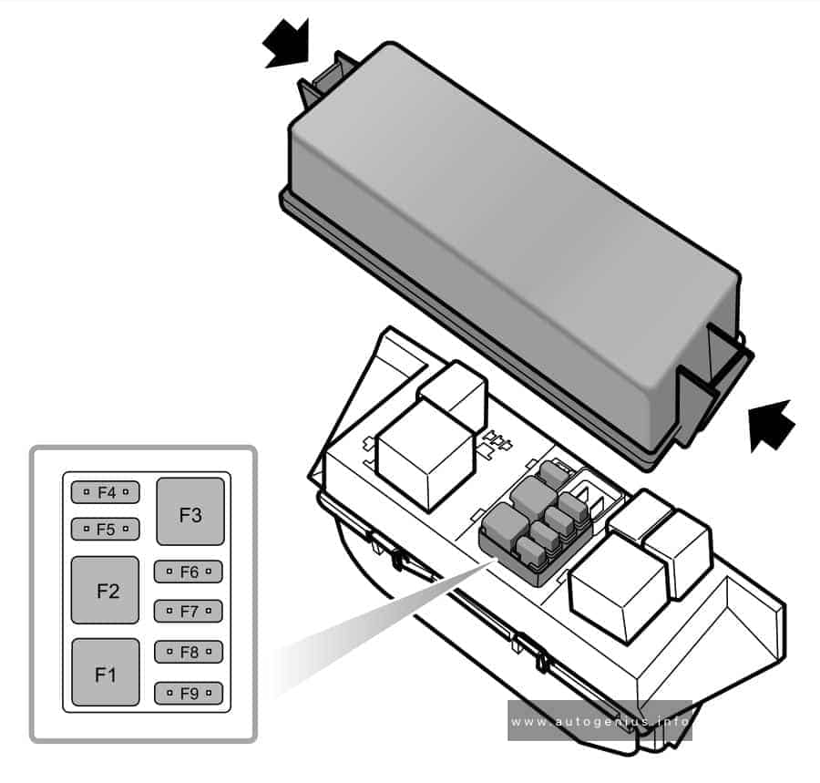
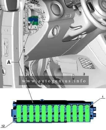
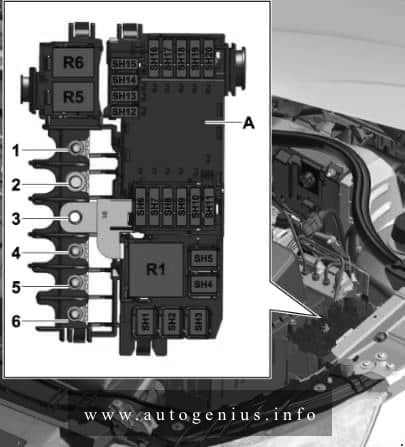
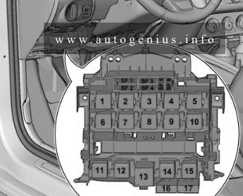
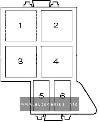
Relays
The relay carrier is above the fuse panel.
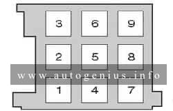
15-pin relay carrier (2010-2011)
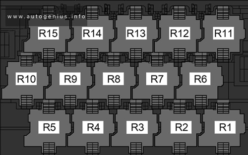
Assignment of the fuses in the relay box (2010 – 2011)
| № | Description |
|---|---|
| R1 | Converter box (E-Box Low, (AWO)) |
| R2 | Fresh air blower relay |
| R3 | Auxiliary heater operation relay -J485- (449) |
| R4 | Fuel Pump Relay Engine Component Power Supply Relay Auxiliary engine coolant pump relay |
| R5 | Low beam relay (E-Box Low, (AWO)) |
| R6 | Fresh air blower relay |
| R7 | Terminal 75 power supply relay 1 |
| R8 | Dual tone horn relay Headlamp washer relay |
| R9 | Power Supply Relay (terminal 50) -J682- (643) |
| R10 | Terminal 15 power supply relay 2 -J681- (643) |
| R11 | Rear window defogger relay -J9- (449) |
| R12 | Fuel pump relay 2 Heat resistance relay Cold start injector relay Fuel primer relay |
| R13 | Power Supply Relay (terminal 50) |
| R14 | Terminal 15 power supply relay |
| R15 | Fog lamp relay |
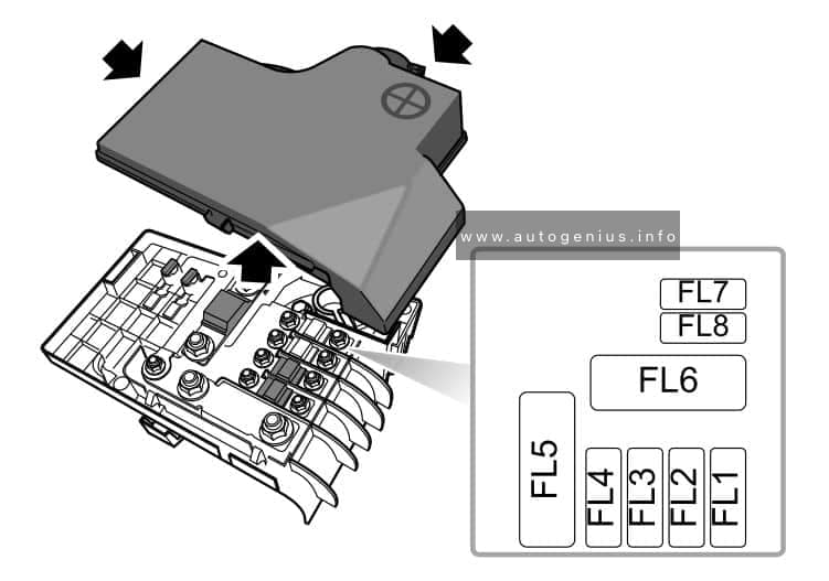
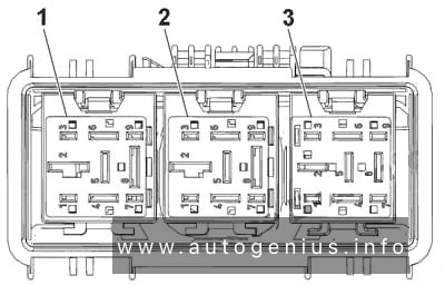
12-pin relay carrier (2012-2017)
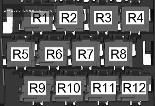
Assignment of the fuses in the relay box (2012 – 2017)
| № | Description |
|---|---|
| R1 | Dual tone horn relay Alarm horn relay (USA and Mexico, E-Box Low) Headlamp washer relay |
| R2 | Power Supply Relay (terminal 50) Starter relay 2 Driver power window opening relay (E-Box high, since 2013) Driver power window closing relay (E-Box high, since 2013) |
| R3 | Cold start injector relay (since 2013) Secondary air injection pump relay (CNLA) Fuel pump relay 2 Front passenger power window opening relay (E-Box high, since 2013) Heat resistance relay Front passenger power window closing relay (E-Box high, since 2013) |
| R4 | Coolant circulation pump relay (up to 2012) Fuel Pump Relay Auxiliary engine coolant pump relay Fuel primer relay Engine Component Power Supply Relay (E-Box high, since 2013) |
| R5 | Terminal 75 power supply relay 1 (up to 2012) |
| R6 | Power Supply Relay (terminal 50) Starter relay 1 |
| R7 | Terminal 15 power supply relay (E-Box Low) Auxiliary heater operation relay (E-Box high) Power window relay (E-Box high, since 2013) |
| R8 | Low beam relay (E-Box Low) Rear window defogger relay (E-Box high) |
| R9 | Terminal 15 power supply relay 2 |
| R10 | Terminal 75 power supply relay 1 |
| R11 | Fog lamp relay (E-Box Low) Fresh air blower relay (E-Box high) Fan activation relay (hybrid) |
| R12 | Converter box (E-Box Low) |
| R13 | Power Supply Relay (terminal 50) |
| R14 | Terminal 15 power supply relay |
| R15 | Fog lamp relay |
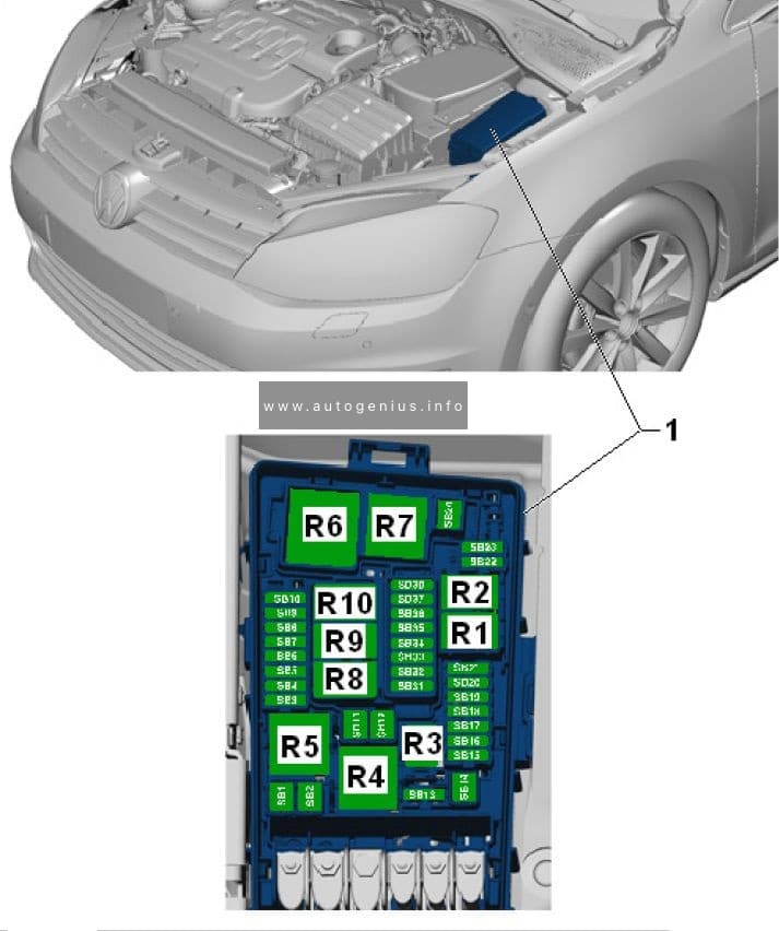
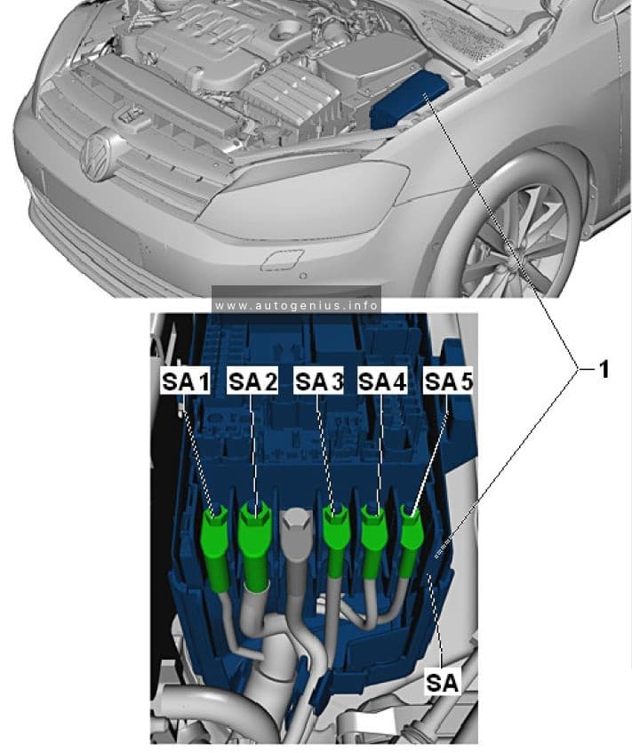
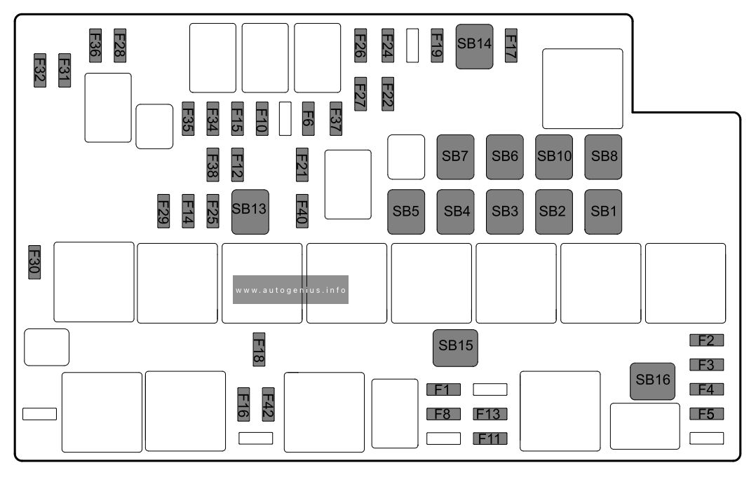
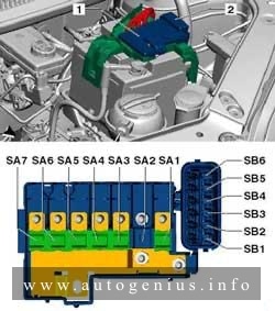
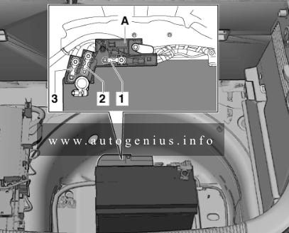
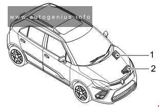
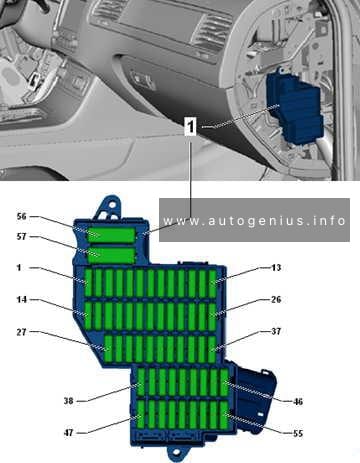
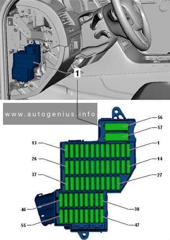
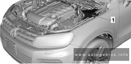
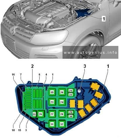
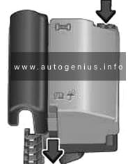
Engine Compartment Fuse Box
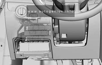
Fuse Box Location
Move the release tabs in the direction of the arrows to unlock the fuse box cover.
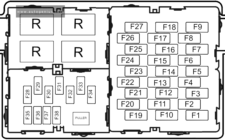
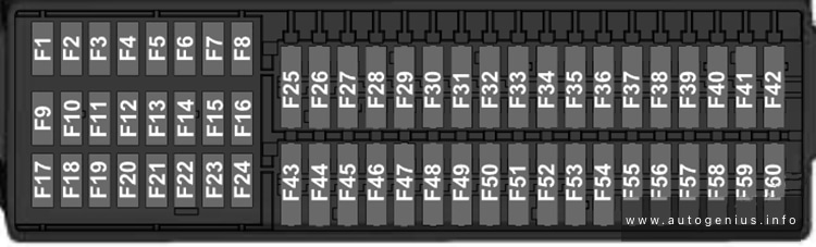
Fuse Box Diagram (-SB-)
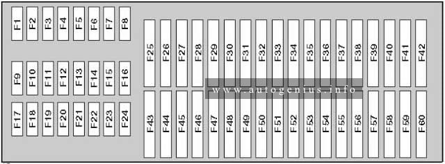
Assignment of the fuses in the engine compartment
| № | Amps | Function/Component |
|---|---|---|
| F1 | – | Not used |
| F2 | 10A/15A | Engine control module Engine component power supply relay |
| F3 | 5A/10A | Coolant fan control module Relay for low heat output Relay for high heat output |
| F4 | 5A/10A/15A | Oxygen sensor heater Heater for oxygen sensor 1 after catalytic converter High temperature circuit coolant pump (Engine codes CNLA, CRJA) Low temperature circuit coolant pump |
| F5 | 5A/10A/20A | Oxygen sensor heater Oxygen sensor 2 heater (Engine codes CNLA, CRJA) Leak detection pump Wastegate bypass regulator valve EGR cooler switch-over valve Positive crankcase ventilation heating element Mass airflow sensor (Engine code CFFB) Vacuum pump relay Brake system vacuum pump |
| F6 | 5A/10A/15A/20A | Leak detection pump EVAP canister purge regulator valve 1 Tank switch-off valve Secondary air injection pump relay |
| F6 | 5A/10A/15A | Water pump Auxiliary heater heating element Relay for low heat output Relay for high heat output |
| F7 | 20A | Petrol: Ignition coil 1~4 with power output stage |
| F7 | 5A | Diesel: Fuel pressure regulator valve Fuel metering valve |
| F8 | 10A | Throttle valve control module Wastegate bypass regulator valve EVAP canister purge regulator valve 1 Camshaft adjustment valve 1 Turbocharger recirculation valve Intake manifold runner control valve Exhaust camshaft adjustment valve 1 (Engine codes CNLA, CRJA) Oil pressure regulation valve (Engine codes CNLA, CRJA) Decoupler pressure actuator (Engine codes CNLA, CRJA) Refrigerant cut-off valve (Engine codes CNLA, CRJA) |
| F9 | 5A/15A | Secondary air injection sensor 1 Secondary air injection sensor 2 Automatic glow time control module Fuel pump relay 2 Fuel pump relay EVAP canister purge regulator valve 1 Camshaft adjustment valve 1 Fuel pressure regulator valve After-run coolant pump Coolant circulation pump relay Engine coolant circulation pump 2 |
| F10 | 5A | Brake lamp switch Clutch position sensor Auxiliary engine coolant pump relay Brake booster relay (Engine codes CNLA, CRJA) Speed sensor |
| F11 | – | Not used |
| F12 | 5A | Ignition coil 1~4 with power output stage After-run coolant pump |
| F13 | 5A/20A | Auxiliary engine coolant pump relay Water pump Brake booster relay (Engine codes CNLA, CRJA) Brake system vacuum pump (Engine codes CNLA, CRJA) |
| F14 | 5A | Engine control module Main relay |
| F15 | 30A | Voltage stabilizer |
| F16 | 30A | ABS control module |
| F17 | 30A | DSG transmission Mechatronic |
| F18 | 20A | DSG transmission Mechatronic |
| F19 | 1A | Vehicle electrical system control module (T52a/24) AW1, (T73b/59) AW0 |
| F20 | 30A | Vehicle electrical system control module (AW0) Wiper/washer intermittent relay (AW1) Wiper motor change-over relay 1 (AW1) Wiper motor change-over relay 2 (AW1) |
| F21 | 50A | Secondary air injection pump motor |
| F22 | 40A | Auxiliary heater heating element |
| F23 | 40A | ABS control module |
| F24 | 50A | Towing recognition control module |
| F25 | 50A | Terminal 15 power supply relay Terminal 15 power supply relay 2 |
| F26 | 50A/40A | Automatic glow time control module Secondary air injection pump relay Secondary air injection pump motor (Engine codes CNLA, CRJA) |
| F27 | 50A/60A | Coolant fan |
| F28 | 40A | Vehicle electrical system control module (AW1) |
| F29 | 40A | Vehicle electrical system control module (AW1) |
| F30 | 50A | Terminal 75 power supply relay 1 |
| F31 | 30A | Amplifier |
| F32 | 40A | Auxiliary heater heating element |
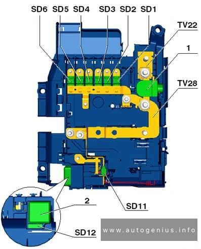
| 508 | Threaded connection (30) on the E-box | |
| SA1 | 200A | Without Hybrid system: Generator With Hybrid system: Electric drive power and control electronics Voltage converter |
| SA2 | – | Not used |
| SA3 | 80A | Steering |
| SA4 | 80A | Without Hybrid system: Interior terminal 30 power supply SC fuses |
| R1 | Wiper motor change-over relay 1 / Not used (AW0) | |
| R2 | Wiper motor change-over relay 2 / Not used (AW0) | |
| R3 | Main relay Terminal 30 power supply relay Fuel primer relay |
|
| R4 | Relay for low heat output Coolant circulation pump relay (Running change) Auxiliary engine coolant pump relay |
|
| R5 | Relay for high heat output Secondary air injection pump relay (gasoline) Brake booster relay (Hybrid, with auxiliary heater) |
|
| R6 | Automatic glow time control module Brake booster relay (Hybrid, without auxiliary heater) |
WARNING: Terminal and harness assignments for individual connectors will vary depending on vehicle equipment level, model, and market.