Volkswagen Caddy (IV; 2015 – 2020) – fuse and relay box diagram
Year of production: 2015, 2016, 2017, 2018, 2019, 2020
The fourth-generation Volkswagen Caddy was produced from 2015 to 2020. In this guide, you will find descriptions of the fuses and relays for the Volkswagen Caddy 4 (2015 – 2020 models), including fuse box diagrams, their locations.
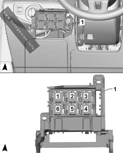
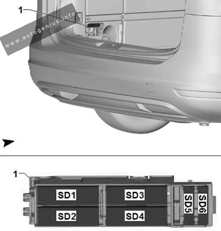
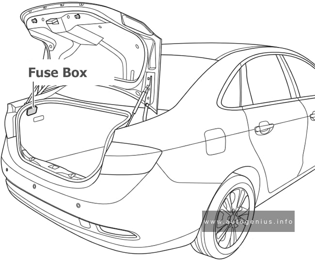
Passenger Compartment
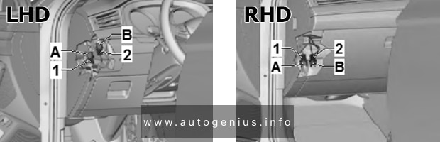
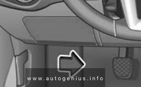
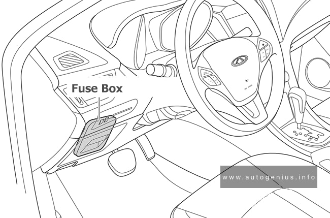
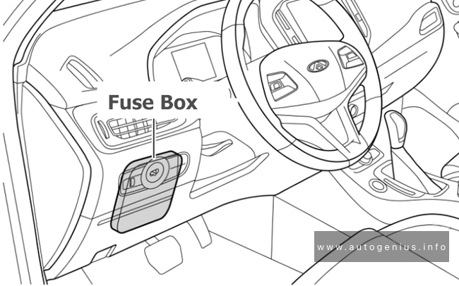
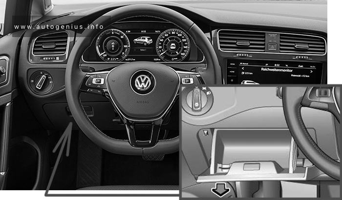
Fuse box location
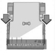
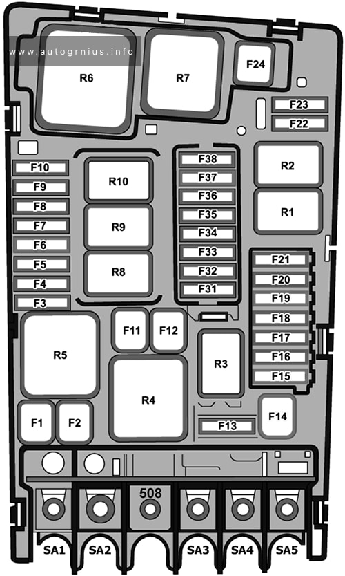
The interior fuse box is located at the bottom of the dashboard, behind a protective cover.
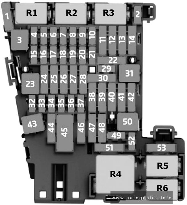
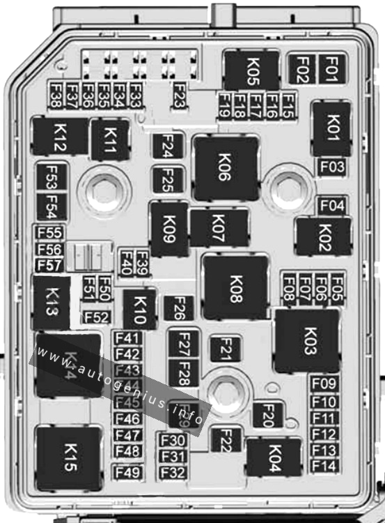
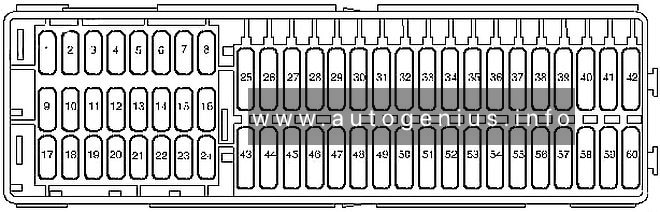
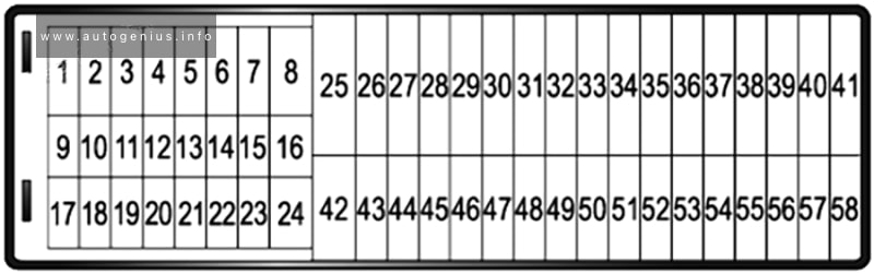
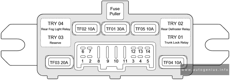
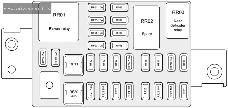
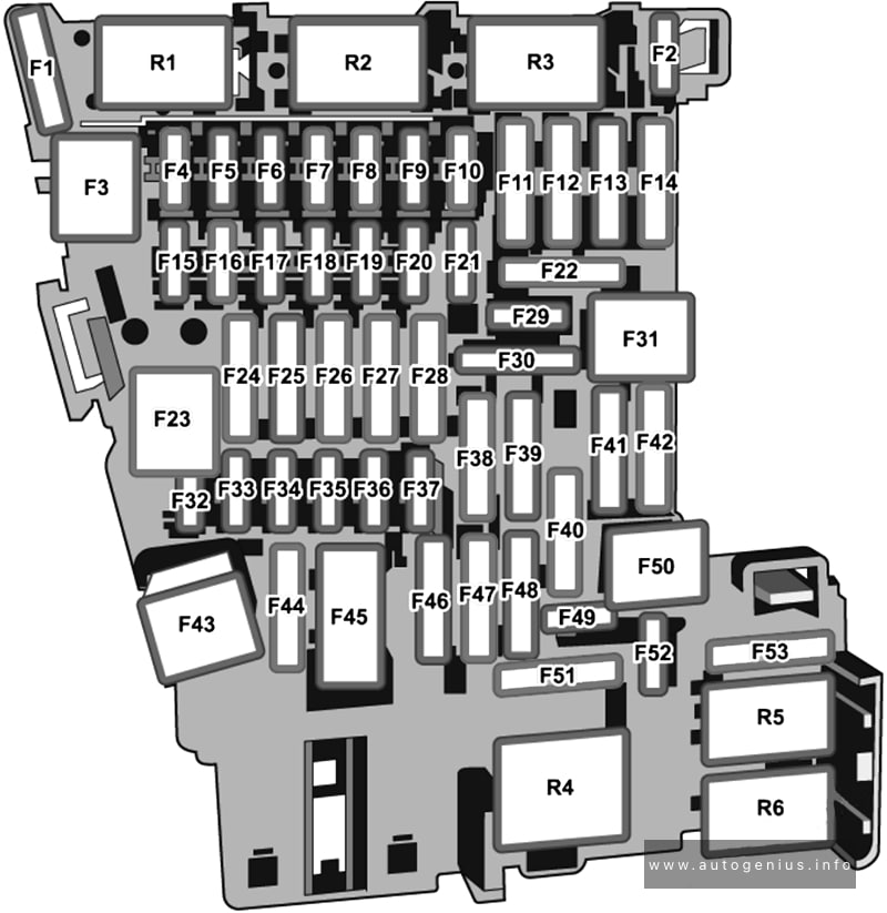
Fuse box diagram
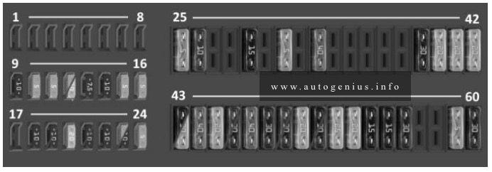
Assignment of the fuses in the passenger compartment
| No. |
A |
Function/component |
| 1 | – | – |
| 2 | – | – |
| 3 | – | – |
| 4 | – | – |
| 5 | – | – |
| 6 | – | – |
| 7 | – | – |
| 8 | – | – |
| 9 | 10 | 10-pin connector, pin 4 (interface for special functions) |
| 10 | 8 | Diagnostic data bus interface. Engine control unit. Starter relay 1. Starter relay 2. |
| 11 | 5 | Parking assistance system control unit unit. Power steering control unit |
| 12 | 5 | Taximeter. Taximeter mirror. |
| 12 | 20 | 8-pin connector, pin 8; 28-pin connector, pin 20 |
| 13 | 7,5 | Headlight range – adjustable. Button for disabling ASR and electronic stability control. Selector lever. Tire pressure indicator button. Start/stop button. ABS control unit. Trailer detection control unit. ACC control unit. Four-wheel drive control unit. Power steering control unit. DSG transmission mechatronic control unit. Inverter with 12 V/230 V socket. Range control motor for left headlamp. Right headlamp range control motor. |
| 14 | 10 | Reverse light switch. Mass air flow sensor. Auxiliary heater switch relay. Control unit in instrument cluster. Crankcase ventilation heater resistor. Diagnostic connector. 1-pole connector, pin sixteen |
| 15 | 5 | Airbag control unit. Front passenger airbag deactivation indicator. |
| 16 | 5 | Lighting switch. Heating and mode selection switch. High pressure sensor. Atmospheric pollution sensor sensor. Temperature and oil level sensor. Light sensor. High beam assistant control unit. Front driver assistance camera. Anti-glare interior mirror. |
| 17 | – | – |
| 18 | 10 | 10-pin connector, pin 6 (interface for special functions) |
| 19 | 10 | Taximeter. Mirror with taximeter. Walkie-talkie. Printer. |
| 19 | 10 | 10 pin connector, pin 7 (interface for special functions) |
| 20 | 20 | Volkswagen Caddy 4 cigarette lighter fuse. 12 V connector, in the storage compartment |
| 21 | 10 | Heating and mode selection operation. Selector lever. Rear window heater relay. Rear window heater relay relay. Climatronic control unit. Air conditioning control unit. Emergency data recorder. (except special equipment for police). Reducing agent dosing system relay. Dual-band cell phone signal amplifier. Radio signal receiver for auxiliary water heater. Bluetooth cell phone antenna. 6-pin connector, 2-pin connector (special police equipment only). Diagnostic connector. 16-pin connector, pin 16 |
| 21 | 10 | Light switch. Heating and heating mode selection switch. Selector switch. Ambient light switch in rear cowl (Camper). Illumination 1 in the tailgate. Illumination 2 in the tailgate. Rain and light sensor. Rear window heater relay. Climatronic control unit. Air conditioning control unit. Horn relay. Emergency data recorder. (Except special equipment for police). Reducing agent. Dosing system relay. 16-pole diagnostic connector, pin 16. Rear interior light (Camper). Illumination 1 in rear of hood. Illumination 2 in the rear of the hood. Rear reversing camera. |
| 22 | 10 | On-board network control unit. Lighting in the passenger compartment. Trunk light. Glove compartment light. Center cabin light. Rear interior light. Backlight 1 in tailgate (special equipment). Backlight 2 in tailgate (special equipment). Trunk light 2 (special equipment). Front left reading light. Front right reading light. Rear left reading lamp 2. Rear right reading light 2. On-board network control unit. Left fog lamp bulb. Right fog lamp bulb. |
| 23 | 5 | [Special vehicles] Taxi – interior light switch. Cab signal switch. 10-pin connector, pin 1 (interface for special functions) |
| 23 | 10 | [special vehicles] Direction indicator relay. |
| 24 | 5 | Interior condition monitoring sensor. Vehicle tilt sensor. Anti-theft alarm sensor. Alarm. on-board network control unit |
| 25 | 5 | Instrument panel. Control unit in the instrument cluster |
| 26 | 10 | Button for emergency data recorder (without special police equipment); Emergency data recorder (without special police equipment) |
| 27 | – | – |
| 28 | – | – |
| 29 | 15 | Rear wiper motor. |
| 30 | – | – |
| 31 | 5 | Heater operating mode switch. Heating resistor for left windshield washer nozzle. Heating resistor for right windshield washer nozzle. |
| 32 | – | – |
| 33 | 40 | Auxiliary heater switch relay ( vehicles with auxiliary heater, without R1234yf refrigerant); Heating mode switch. Air conditioner control unit. Auxiliary heater switch relay (cars with auxiliary heater, with R1234yf refrigerant); Fresh air fan cut-off relay. Heating mode switch. Air conditioner control unit. Outside air fan isolation relay (vehicles without auxiliary heater, with R1234yf refrigerant); Air conditioner control unit. |
| 34 | – | – |
| 35 | – | – |
| 36 | – | – |
| 37 | – | – |
| 38 | – | – |
| 39 | 30 | 4-pin connector, pin 1 [special vehicles]. |
| 40 | 20 | Trailer detection control unit. |
| 41 | 20 | Trailer detection control unit. |
| 42 | 20 | Trailer detection control unit. |
| 43 | 15 | Fuel pump relay (Caddy gasoline pump fuse). Fuel pump. High pressure fuel supply relay. Additional fuel pump. Electric fuel pump relay 2. |
| 43 | 20 | [Euro 6 diesel engine] – Fuel pump relay. Electric fuel pump relay 2. Fuel pump. |
| 44 | 40 | Fresh air blower control unit. Fresh air blower. |
| 45 | 20 | Headlight washer relay. Headlamp washer pump. |
| 46 | 10 | Driver’s door control unit. (models without power windows), left-hand drive vehicles / Passenger door control unit. models without power windows), right-hand drive vehicles |
| 46 | 30 | Driver door control unit (models with power windows), left-hand drive vehicles / Passenger door control unit (models with power windows), right-hand drive vehicles |
| 47 | 40 | X relay relay relay contact, fuse box C in the passenger compartment. |
| 48 | 30 | Front seat heating control unit. |
| 49 | 10 | Driver door control unit (models without power windows), right-hand drive vehicles / Passenger door control unit (models without power windows), left-hand drive vehicles |
| 49 | 30 | Driver door control unit (models with power windows), right-hand drive vehicles / Passenger door control unit (models with power windows), left-hand drive vehicles |
| 50 | 20 | On-board network control unit. Windshield washer pump. Rear wiper motor. Windshield and rear window washer pump. |
| 51 | 15 | Trailer power relay. TCU connector. |
| 51 | 30 | 10-pin connector, pin 4 / 10-pin connector, pin 5 [special vehicles]. |
| 52 | 25 | Rear window defroster relay. Rear window defroster resistor. Left hinged door rear window defroster resistor. Right hinged door rear window defroster resistor. Fresh air fan relay (vehicles with auxiliary heater). Ballast resistor for fresh air fan with overheating protection. Fresh air blower. |
| 53 | 20 | 12V outlet – rear in center console; 12V outlet in left rear side panel. |
| 54 | 15 | Roof fan switch relay 1. [special vehicles]. |
| 55 | 15 | 8-pin connector, pin 4 [special cars] |
| 56 | 30 | Inverter with socket, 12V/230V. |
| 57 | – | – |
| 58 | – | – |
| 59 | 5 | Radio switch. Engine boost switch. Daytime running lights switch. Emergency data logger. |
| 60 | 30 | 3-pin connector, pin 1 [special vehicles]. |
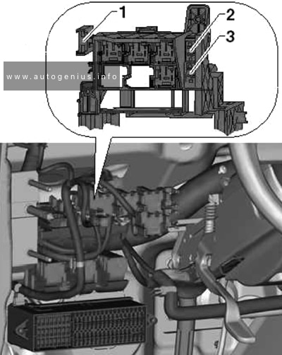
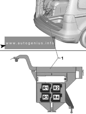
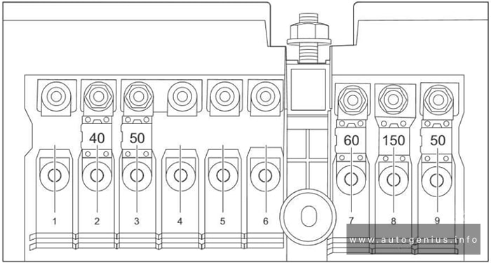
Engine Comparment
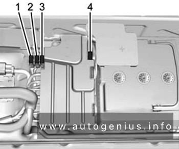
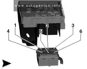
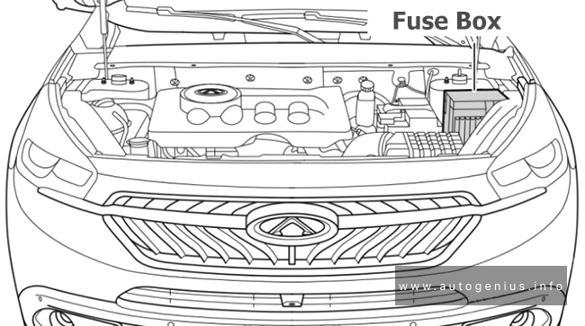
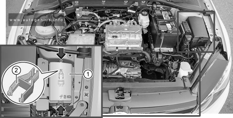
Fuse box location
In the engine bay, the fuse and relay box is positioned next to the battery and protected by a cover.
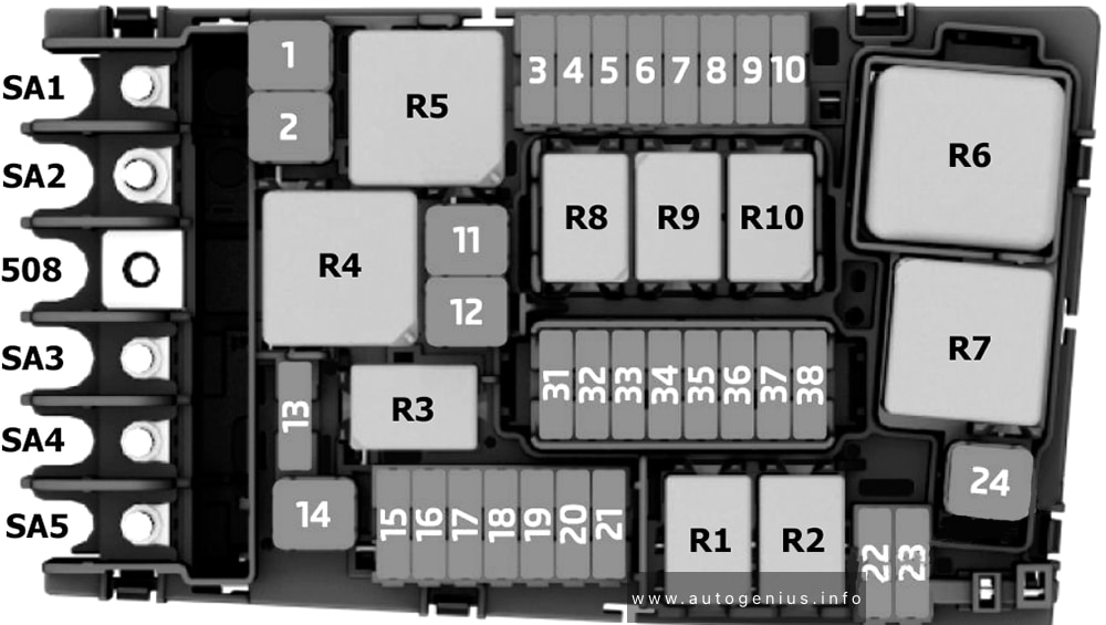
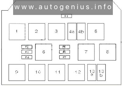
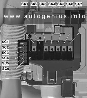
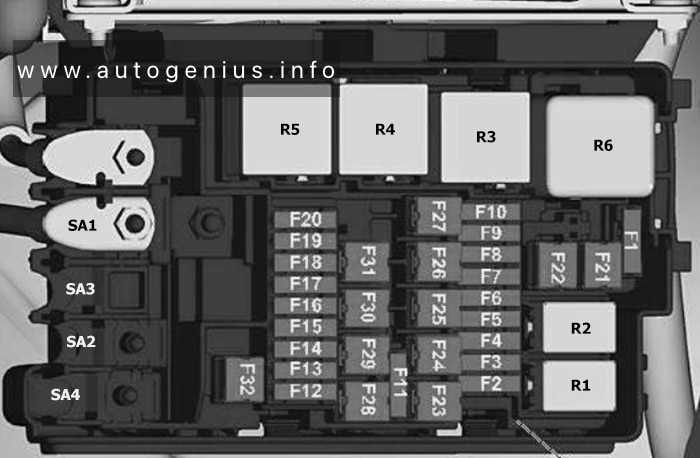
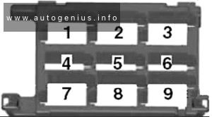
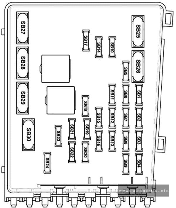
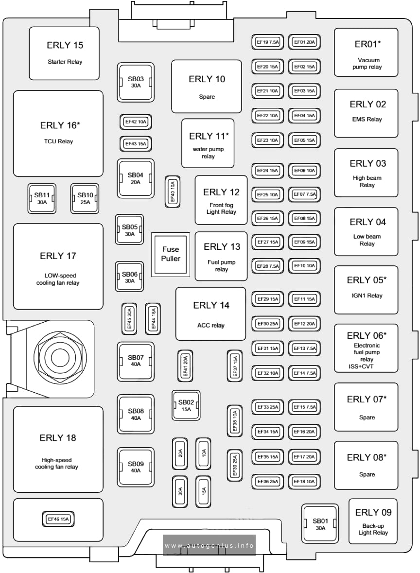
Fuse box diagram
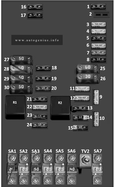
Assignment of the fuses in the engine compartment
| No. |
A |
Function/component |
| 1 | 30 | Gearbox heating control unit |
| 2 | – | – |
| 3 | 5 | Battery condition monitoring control unit, board power control unit |
| 4 | 20 | ABS control unit, ABS hydraulic unit |
| 5 | 15 | DSG transmission mechatronic unit (02E) with 20-pin connector |
| 5 | 30 | DSG transmission mechatronic unit (0AM) with 25-pin connector |
| 6 | 5 | Before May 2017: Instrument cluster control unit, Steering column electronics control unit; From June 2017 [For left-hand drive vehicles]: Light switch, Trunk lid illumination switch (Camper), Trunk lid illumination 1, Trunk lid illumination 2, Rain and light sensor, Horn relay, Instrument cluster control unit, Steering column electronics control unit, Emergency call module and communication control unit, Reverse camera, Rear interior light (Camper), Rear lid illumination 1, Rear lid illumination 2; From June 2017 [For right-hand drive vehicles]: Control unit in instrument cluster, Electronic steering column control unit, Dual-band cell phone signal booster, Bluetooth cell phone antenna. |
| 7 | 40 | Power relay terminal 15: Interior fuse box (#9 – #16 and #25 – #27) |
| 8 | 15 | Control unit with display for radio with navigation, control unit 1 for information electronics, radio, USB hub |
| 9 | 20 | Wheel drive control unit |
| 10 | 5 | Engine control unit, main relay [gasoline engine], power relay terminal 30 [diesel engine] |
| 11 | 20 | Auxiliary heater control unit |
| 12 | 5 | Diagnostic data bus interface |
| 13 | 15 | Engine control unit [Petrol engine] |
| 13 | 30 | Engine control unit [Diesel engine] |
| 14 | 10 | [Diesel engine, complies with Euro 6 emission standard]: Inlet camshaft adjustment valve 1, Fuel pressure regulator, Fuel metering valve |
| 14 | 15 | [Diesel engine, compliant with Euro 5, Euro 4 emission class]: Fuel pressure regulator, Fuel metering valve |
| 14 | 20 | Ignition coil, Ignition coil 1, 2, 3 and 4 with output stage |
| 15 | 5 | Fuel pump relay, Electric fuel pump relay 2, Glow plug control unit; [Diesel engine complying with Euro 5, Euro 4 emission class]: Low output heater relay, High output heater relay |
| 15 | 10 | Lambda probe heating element, Lambda probe heating element 1 after catalytic converter |
| 15 | 15 | [Diesel engine compliant with Euro 6 emission standard]: Low output thermal relay, High output thermal relay; NOx sensor control unit, NOx sensor control unit 2, Lambda probe heating element; Injectors for cylinders 1, 2, 3 and 4 [Petrol engine 1.6L]. |
| 16 | 30 | On-board network control unit, Front right headlamp, Right headlamp discharge lamp control unit, Right daytime running lamps and front side lamps control unit, Right headlamp bulb for adaptive lighting system, Left fog lamp or right fog lamp bulb, Right daytime running lamps bulb, Front left lamp, Rear right lamp, Front right lamp, Rear left turn signal lamp, Front right turn signal lamp, Left brake light bulb, Right reversing light bulb, Left turn signal lamp, Left turn signal repeater bulb, High beam bulb, Right low beam bulb, Right high beam bulb, Right high beam bulb |
| 17 | 15 | Horn relay: High tone signal |
| 18 | 30 | Control unit for special vehicles |
| 19 | 30 | Windshield wiper motor control unit: Windshield wiper motor |
| 20 | 10 | Shut-off and safety valve 1, 2, 3, 4 and 5 for gas cylinder |
| 21 | 10 | [Diesel engine, complies with Euro 6 emission standard]: Fuel pump relay, glow plug control unit; lambda probe heating element [Diesel engine, complies with Euro 5, Euro 4 emission standards]. |
| 21 | 15 | Fuel pump control unit [Gasoline engine]; [Gasoline engine 1.6 l]: Lambda probe heater, Lambda probe heater 1 after catalytic converter |
| 21 | 30 | [Gasoline engine 1.0 l]: Fuel pump control unit, Brake system vacuum pump |
| 22 | 5 | Brake light switch, Clutch pedal position sensor |
| 23 | 15 | Mass air meter, Charge pressure control solenoid valve, EGR cooler switch valve, Oil pressure control valve, Cylinder head cooling circuit valve, Gas cut-off valve relay, High pressure valve for gas operation, Charge air cooling pump |
| 23 | 15 | Fuel pressure regulator, Charge air cooling pump |
| 24 | 10 | Radiator fan: Radiator fan control unit; Relay for reducing agent metering system: Reducer level sensor, Recovery pump, Reducer return pump; Canister solenoid valve 1, Intake camshaft adjustment valve 1, Exhaust camshaft adjustment valve 1, Gas injection valve 1, 2, 3 and 4, Oil pressure adjustment valve, Coolant circulation pump 2, Charge air cooling pump, Heater circulation pump |
| 25 | 60 | ABS control unit, ABS hydraulic pump |
| 26 | 30 | On-board power control unit, Front left headlight, Adaptive lighting system left headlight bulb, Left headlight discharge lamp control unit, Left daytime running lamps and front side headlamps control unit, Left fog lamp bulb or right fog lamp bulb, Left daytime running lamps bulb, Front right lamp bulb, Left rear lamp bulb, Front left turn signal lamp, Rear right turn signal lamp, Right brake light bulb, Left reversing light bulb, Right turn signal repeater bulb, Left low beam bulb, Left high beam bulb, Left low beam bulb, Left high beam bulb, Left low beam headlamp flap |
| 27 | 50 | Glow plug control unit |
| 28 | 40 | Fuse 56 in the passenger compartment fuse box, Inverter with 12V/230V socket |
| 28 | 60 | Windshield heater relay: Windshield heater element |
| 29 | 30 | Special vehicles: Fuse 18 and 19 in the passenger compartment fuse box |
| 29 | 50 | Special vehicles: Fuse 39 in the passenger compartment fuse box, Fuse 51 in the passenger compartment fuse box, Fuses 54 and 55 in the passenger compartment fuse box, Fuses 59 and 60 in the passenger compartment fuse box |
| 30 | 50 | Trailer Driving: Fuse 40, 41 and 42 in the passenger compartment fuse box |
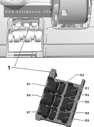
| R1 | Main relay, Power relay terminal 30 | |
| R2 | Gas shutoff valve relay | |
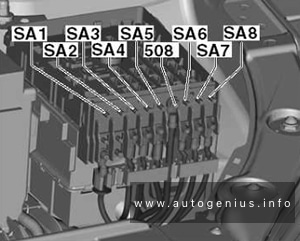
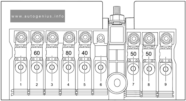
| SA1 | 200 | Alternator (110A); Alternator (140A/180A) |
| SA1 | 400 | Alternator (140A/180A) |
| SA2 | 80 | Power steering control unit: Power steering motor |
| SA3 | 50 | Radiator fan: Radiator fan control unit, radiator fan, radiator fan 2 |
| SA4 | 80 | Contact relief relay X [Cars without Climatronic only]: Interior fuse box: No. 20 – No. 24 and No. 43 – No. 53 |
| SA5 | 80 | Interior fuse box: No. 20 – No. 24 and No. 43 – No. 53 |
| SA6 | 40 | Low power heating relay: Heating element for auxiliary air heater |
| SA7 | 80 | High power heating relay: Heating element for auxiliary air heater |
| TV2 | Protection of all circuits in underhood block |
There are also videos on this topic on our YouTube channel.
WARNING: Terminal and harness assignments for individual connectors will vary depending on vehicle equipment level, model, and market.