The MG HS, a compact crossover, has been in production since 2019. This article features fuse box diagrams for the 2019, 2020, 2021, 2022, and 2023 models, provides details on the locations of the fuse panels inside the vehicle, and explains the function of each fuse (fuse layout).
Assignment of the fuses in the passenger compartment
No.
A
Protected components
F1
10A
Supplemental Restraint System Sensing and Diagnostic Module, DC-DC Converter, Communication Module, Shifter Control Unit, Instrument Pack, Body Control Module, SDM Auxiliary Display Module
F2
7.5A
Transmission Control Module, Reverse Lamp Switch, Engine Control Module
MG ZS EV (2019 – 2021) – fuse and relay box diagram
Year of production: 2019, 2020, 2021
The pre-facelift MG ZS EV, a subcompact electric crossover, was produced from 2019 to 2021. This article includes fuse box diagrams for the 2019, 2020, and 2021 models, provides details on the locations of the fuse panels inside the vehicle, and explains the function of each fuse (fuse layout).
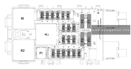
Passenger Compartment Fuse Box
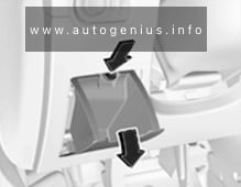
Fuse Box Location
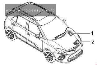
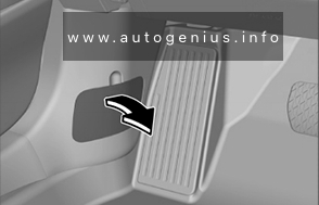
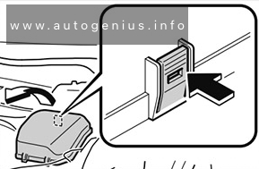
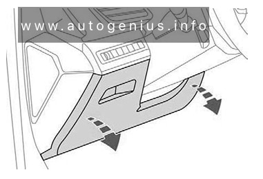
The fuse panel is located below the glove box at the front passenger side.
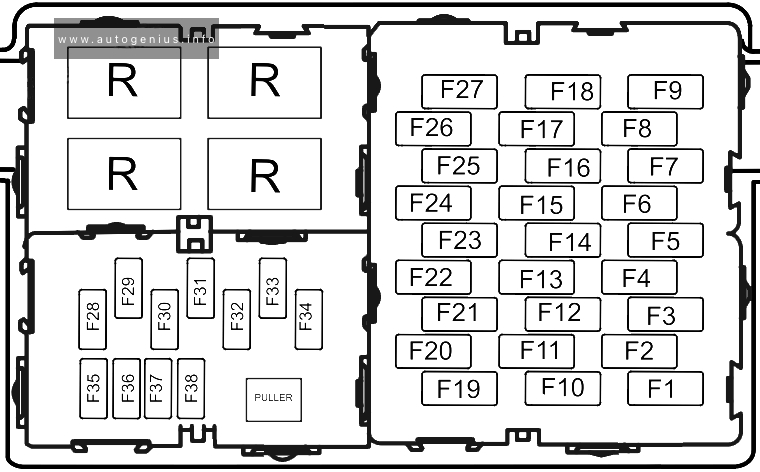
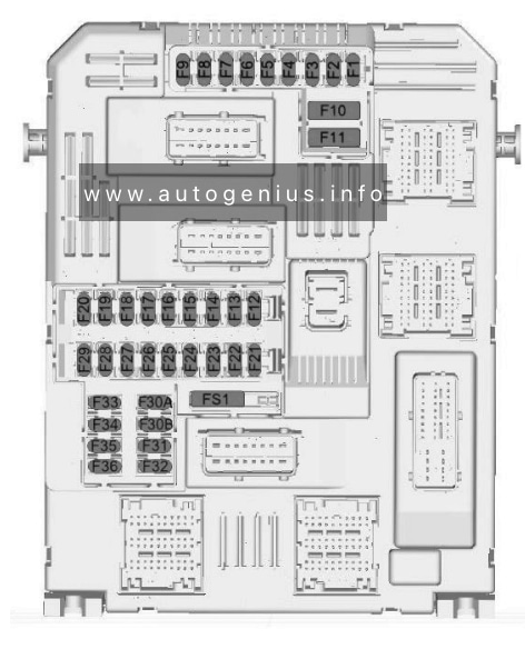
Fuse Box Diagram
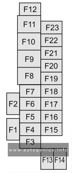
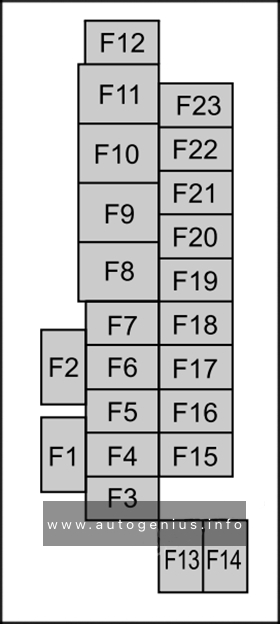
MG ZS EV (2019 – 2021) – fuse and relay box diagram – passenger compartment fuse box
Assignment of the fuses in the passenger compartment
This article focuses on the second-generation MG MG3, following its second facelift, produced from 2018 to 2023. It includes fuse box diagrams for the 2019 through 2023 models, provides details on the locations of the fuse panels inside the vehicle, and explains the function of each fuse (fuse layout).
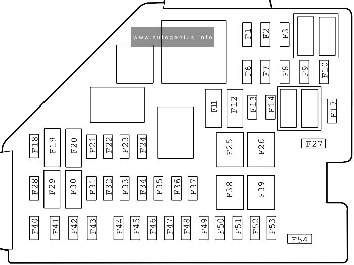
The Mazda CX-30, a compact crossover SUV, has been in production since 2019. In this article, you’ll find fuse box diagrams for the 2019, 2020, 2021, 2022 and 2023 models, along with information on the locations of the fuse panels inside the vehicle and details on each fuse’s function and layout.
Passenger compartment fuse box
Fuse Box Location
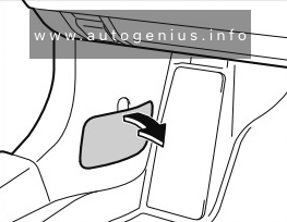
It is located behind the cover on the left side of the vehicle.
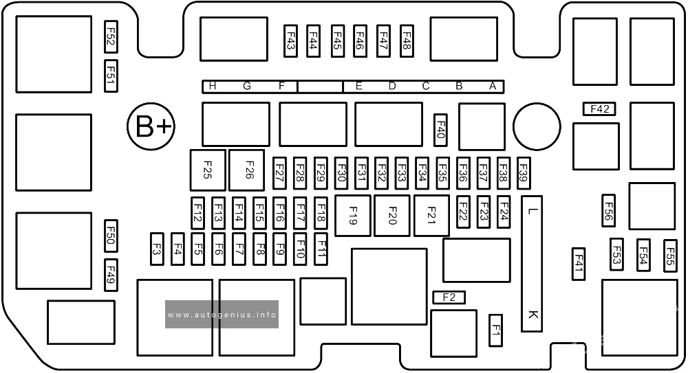
Year of production: 2019, 2020, 2021, 2022, 2023, 2024
This article focuses on the fourth-generation Mazda 3 (BP), produced from 2019 to the present. It includes fuse box diagrams for the 2019 through 2024 models, details the locations of the fuse panels within the vehicle, and provides information on the function and layout of each fuse and relay.
Passenger compartment fuse box
Fuse box location
It is located on the left side of the vehicle, behind the cover.
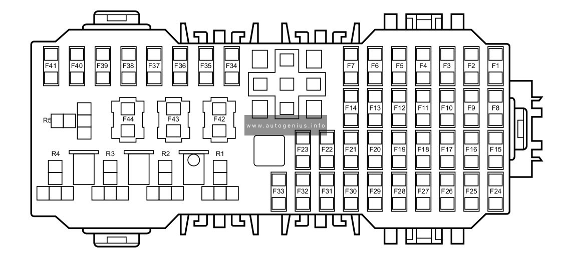
Year of production: 2017, 2018, 2019, 2020, 2021, 2022, 2023, 2024
The Opel Grandland X was produced from 2017 to 2024 and underwent a restyling during its production run. It is also known as the Vauxhall Grandland. In this post, you’ll find detailed information about the fuses and relays in the Grandland, including fuse box diagrams, their locations.
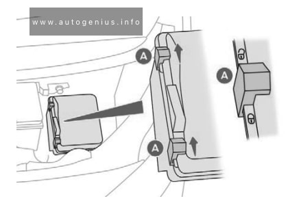
Passenger compartment fuse box
Fuse Box Location
The main fuse box is located on the left side at the bottom of the instrument panel.
Engine computer l Charge pump (for ER6EDT) – ignition coils (EB2ADTS and EP6FADTX)
F21
30
Starter
F22
40
Reserve – Taxi
F23
40
Starter/Alternator
F24
40
Fuse box in passenger compartment 5
F25
40
Interior fuse box 3
F26
15/20
Heater
F27
25
Intelligent Switching Unit (Right Low Beam Headlight – Right Reversing Lights – Left Fog Lights – Left Rear Parking Lights – Third Brake Light.)
F28
30
Power supply for urea pump and urea tube heating resistor (UCE or DV5R) – Nox sensor (DW10F) – Engine computer (EP6FADTX) – (BlueInjection, AdBlue)
F29
40
Windshield wiper
F30
80
Pre-heating unit
F31
80
Switching and protection unit
F32
80
Power steering, Left low beam headlight – Static turn lights – Side turn indicators – Left turn indicators – Front left and rear right side lights – Left brake lights – License plate lights.
Relay
R1
Engine control computer / Euro6 diesel (SCR module power supply)
R2
Air Conditioning Compressor/Heated Windshield
R3
Starter / thermal preconditioning
R4
Fog lights/daytime running lights
R5
Air conditioner fan
R6
Starter
R7
Front wiper
R8
Front wiper
R9
Battery fuse box
Fuse Box Location
A high power fuse box is attached to the positive terminal of the battery.
Opel Grandland (2017 – 2021) – fuse and relay box diagram
Year of production: 2017, 2018, 2019, 2020, 2021, 2022, 2023, 2024
The Opel Grandland X was produced from 2017 to 2024 and underwent a restyling during its production run. It is also known as the Vauxhall Grandland. In this post, you’ll find detailed information about the fuses and relays in the Grandland, including fuse box diagrams, their locations.
Passenger compartment fuse box
Fuse Box Location
The main fuse box is located on the left side at the bottom of the instrument panel.
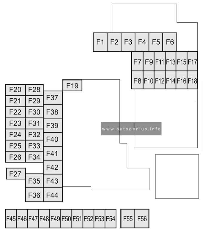
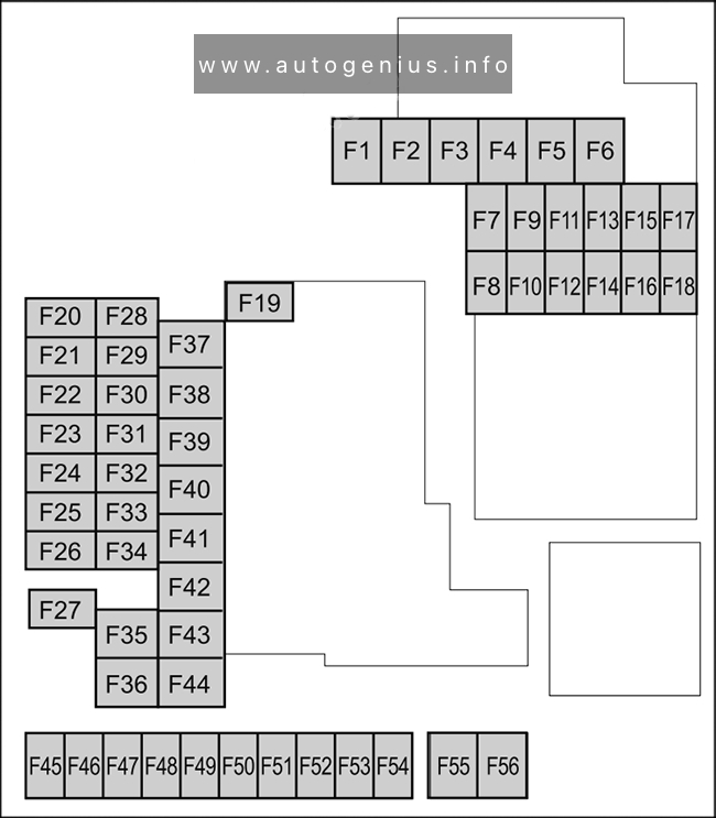
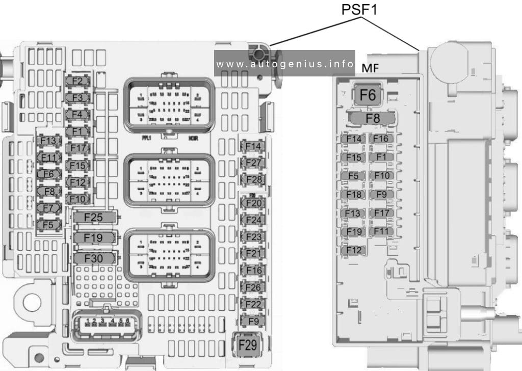
Opel Grandland (2017 – 2024) – fuse and relay location – passenger compartment
Fuse Box Diagram
Opel Grandland (2017 – 2024) – fuse and relay diagram – passenger compartment
Type 1
Assignment of the fuses in the passenger compartment (type 1)
№
Description
1
Interior mirror / Electric power steering wheel / Selective drive control / Radar / Diesel exhaust system
3
Trailer Position Control Module
4
Signal
5
Window washer (front/rear)
6
Window washer (front/rear)
7
Rear socket
8
Rear wiper
10
Door lock/rear door lock
11
Door lock/rear door lock
12
Stop-Start System / Diagnostic Connector Module / Brake System
13
Infotainment system / Climate control system
14
Alarm siren
15
Climate control system
16
Stop-start/Brake system
17
Instrument panel
18
Parking assistant
19
Steering Column Electrical System / Steering Wheel Controls
21
Anti-theft alarm
22
Camera / Rain sensor / Automatic lighting control
23
Seat belt reminder
24
Automatic Transmission /Advanced Parking Assist / Panoramic View System
Engine computer l Charge pump (for ER6EDT) – ignition coils (EB2ADTS and EP6FADTX)
F21
30
Starter
F22
40
Reserve – Taxi
F23
40
Starter/Alternator
F24
40
Fuse box in passenger compartment 5
F25
40
Interior fuse box 3
F26
15/20
Heater
F27
25
Intelligent Switching Unit (Right Low Beam Headlight – Right Reversing Lights – Left Fog Lights – Left Rear Parking Lights – Third Brake Light.)
F28
30
Power supply for urea pump and urea tube heating resistor (UCE or DV5R) – Nox sensor (DW10F) – Engine computer (EP6FADTX) – (BlueInjection, AdBlue)
F29
40
Windshield wiper
F30
80
Pre-heating unit
F31
80
Switching and protection unit
F32
80
Power steering, Left low beam headlight – Static turn lights – Side turn indicators – Left turn indicators – Front left and rear right side lights – Left brake lights – License plate lights.
Relay
R1
Engine control computer / Euro6 diesel (SCR module power supply)
R2
Air Conditioning Compressor/Heated Windshield
R3
Starter / thermal preconditioning
R4
Fog lights/daytime running lights
R5
Air conditioner fan
R6
Starter
R7
Front wiper
R8
Front wiper
R9
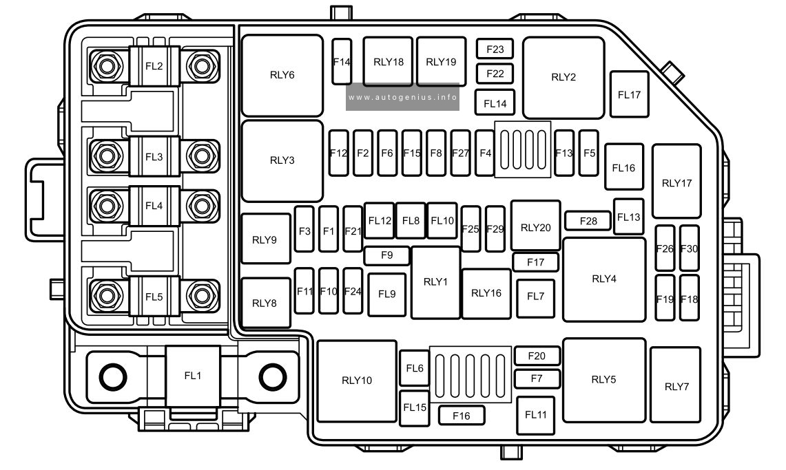
Battery fuse box
Fuse Box Location
A high power fuse box is attached to the positive terminal of the battery.
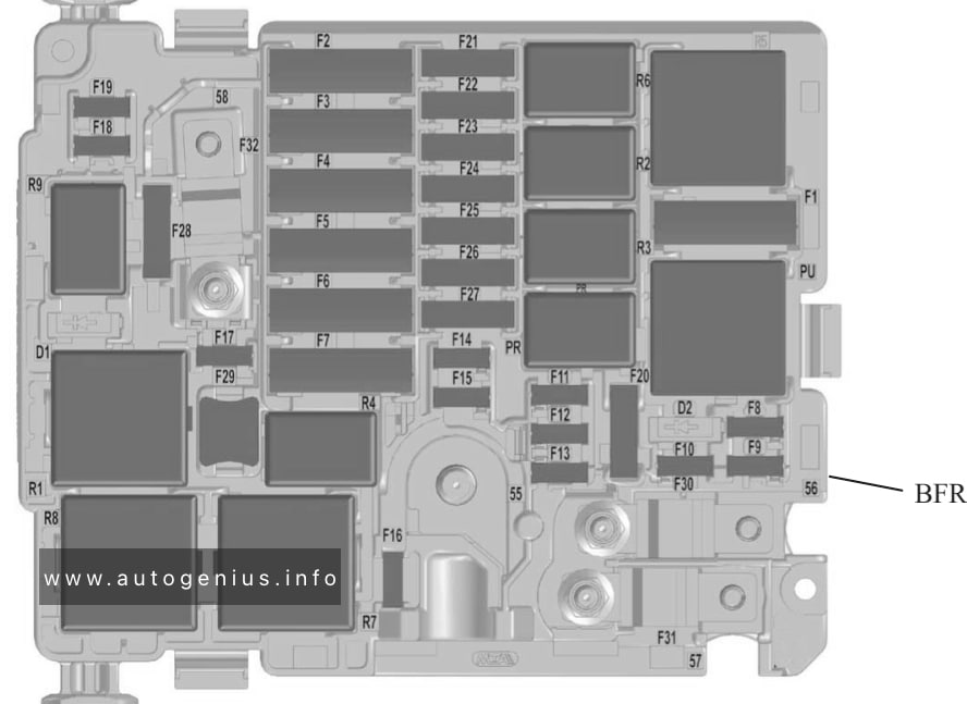
Fuse Box Diagram
Opel Grandland (2017 – 2024) – fuse and relay diagram – battery fuse box
Assignment of the fuses in battery fuse box
№
Amp
Description
1
60
Electrical control unit for two-speed fan motor
2
100
Fuse box
3
80
Power steering
4
80
Interior fuse box
5
80
Interior fuse box
WARNING: Terminal and harness assignments for individual connectors will vary depending on vehicle equipment level, model, and market.
Vauxhall Corsa F (2019 – 2024) – fuse and relay box diagram
Year of production: 2019, 2020, 2021, 2022, 2023, 2024
The Opel Corsa F is the sixth generation of the Corsa lineup, produced from 2019 to 2024. It is also known as the Vauxhall Corsa F. This article provides an overview of the fuses and relays in the Corsa F, including fuse box diagrams, locations.
Passenger compartment fuse box
Fuse Box Location
The main fuse box is located on the left side at the bottom of the instrument panel.
Vauxhall Corsa F (2019 – 2024) – fuse and relay location – passenger compartment
Fuse Box Diagram
Vauxhall Corsa F (2019 – 2024) – fuse and relay diagram – passenger compartment
Assignment of the fuses in the passenger compartment.
№
Description
1
Interior mirror / Electric power steering wheel / Selective drive control / Radar / Diesel exhaust system
3
Inductive charging
4
Signal
5
Window washer (front/rear)
6
Window washer (front/rear)
7
Rear socket / USB
8
Rear wiper
10
Door lock/rear door lock
11
Door lock/rear door lock
12
Stop-Start System / Diagnostic Connector Module / Brake System
13
Infotainment system / Climate control system
14
Alarm siren
15
Non Electric cars: Empty
Electric cars: Electronic shifter module /
Headlight control unit
16
Stop-start/Brake system
17
Instrument panel
18
Parking assistant
19
Steering Column Electrical System / Steering Wheel Controls
21
Anti-theft alarm
22
Camera / Rain sensor / Automatic lighting control
23
Seat belt reminder
24
Automatic Transmission /Advanced Parking Assist / Panoramic View System
This fuse box is located behind the main fuse box.
Fuse Box Diagram
Vauxhall Corsa F (2019 – 2024) – fuse and relay diagram – passenger compartment (behind main fuse box)
Assignment of the relays in the passenger compartment (behind main fuse box)
Number
Description
F1
Heater / rear window defroster
F2
Heated exterior side mirrors
F3
Electric windows – front
F4
Folding side mirrors / Adjustable outside mirrors
F5
Power windows – rear
F6
Seat heating
F7
–
F8
Fuse Box (Right Side of Dashboard)
F9
–
F10
Heated front seats
F11
Front seat massage function
F12
Empty (reserved)
Relay
R01
Seat heating relay
R02
Power window relay
R03
Rear window defroster/ heater relay
R04
–
R05
–
R06
–
R07
–
Engine compartment fuse box
Fuse Box Location
In the engine compartment, under the hood, on the left side, next to the battery, there is a fuse and relay box.
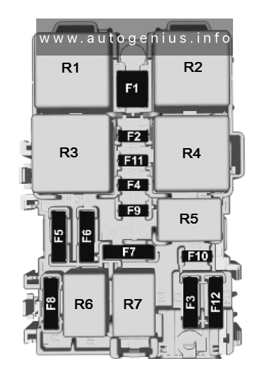
Fuse Box Diagram
Vauxhall Corsa F (2019 – 2024) – fuse and relay diagram – engine compartment
Assignment of the fuses in the engine compartment
№
Description
F1
Air conditioner fan
F2
ABS / ESP computer
F3
Interior fuse box 3
F4
ABS / ESP computer
F5
Intelligent Switch Unit (Right turn signals, front right side marker lights, right brake lights, left reverse lights, right fog lights.) 20A Heated windshield
F6
Two-speed cooling fan control unit (GMV) 20A Calculator BVA AxN8 – Calculator BVA Ax6III (thermal)
F7
Intelligent Switch Box
F8
Engine control fuel pump
F9
Piloted lift pump (DW10F), intake and exhaust valves v solenoid valves – Piloted thermostat – Oil pump solenoid valve (EC flush – Electrical solenoid valve – Intake air flow meter – Oxygen sensors (EP6FADTX), Piloted thermostat – Switchable Water Supply Electric Solenoid Valve (EP6FDT)
F10
Engine Computer – Diesel Flow Control Pump Solenoid – Turbocharger Pressure Control Solenoid Valve (DV5R and DW10F) – Thermostat S (DV5R) – Purge Heater – Adjustable Intake and Exhaust Solenoid Valves (EP6FADTX) – Cylinder Flush – Oxygen Sensors Raised (EB2ADTS) )
F11
Engine computer
F12
Diagnostic link connector
F13
Intelligent Switch Box
F14
Battery charge level block
F15
Heated windshield
F16
Trailer control module
Electric cars: E-service plug
Engine Computer l Charge Pump (for ER6EDT) – Ignition Coils (EB2ADTS and EP6FADTX)
F21
Starter
F22
Reserve – Taxi
F23
Starter/Generator / AC/DC converter
F24
Tow hitch
F25
Interior fuse box 3
F26
Transmission control module / Electric cars: Motor controller (electric motor and inverter)
F27
Intelligent Switching Unit (Right Low Beam Headlight – Right Reversing Lights – Left Fog Lights – Left Rear Parking Lights – Third Brake Light.)
F28
Urea pump power supply and urea tube heating resistor (UCE or DV5R) – Nox sensor (DW10F) – Engine computer (EP6FADTX) (BlueInjection, AdBlue)
F29
Windshield wiper
F30
Pre-heating block
F31
Climate control system (Heating and ventilation system), AC and Heater Blower
F32
Power Steering, Left Low Beam Headlight – Static Turning Lights – Side Indicator Lights – Left Turn Signal Lights – Front Left and Rear Right Side Lights – Left Brake Lights – License Plate Lamps.
Relay
R1
Engine control computer / Euro6 diesel (SCR module power supply)
R2
Air Conditioning Compressor/Heated Windshield
R3
Starter / thermal preconditioning
R4
Fog lights/daytime running lights
R5
Air conditioner fan
R6
Starter
R7
Front wiper
R8
Front wiper
R9
Headlights
R7
Front wiper
R8
Front wiper
R9
Headlights
WARNING: Terminal and harness assignments for individual connectors will vary depending on vehicle equipment level, model, and market.
Opel Corsa F (2019 – 2024) – fuse and relay box diagram
Year of production: 2019, 2020, 2021, 2022, 2023, 2024
The Opel Corsa F is the sixth generation of the Corsa lineup, produced from 2019 to 2024. It is also known as the Vauxhall Corsa F. This article provides an overview of the fuses and relays in the Corsa F, including fuse box diagrams, locations.
Passenger compartment fuse box
Fuse Box Location
The main fuse box is located on the left side at the bottom of the instrument panel.
Opel Corsa F – fuse and relay location – passenger compartment
Fuse Box Diagram
Opel Corsa F (2019 – 2024) – fuse and relay diagram – passenger compartment
Assignment of the fuses in the passenger compartment.
№
Description
1
Interior mirror / Electric power steering wheel / Selective drive control / Radar / Diesel exhaust system
3
Inductive charging
4
Signal
5
Window washer (front/rear)
6
Window washer (front/rear)
7
Rear socket / USB
8
Rear wiper
10
Door lock/rear door lock
11
Door lock/rear door lock
12
Stop-Start System / Diagnostic Connector Module / Brake System
13
Infotainment system / Climate control system
14
Alarm siren
15
Non Electric cars: Empty
Electric cars: Electronic shifter module /
Headlight control unit
16
Stop-start/Brake system
17
Instrument panel
18
Parking assistant
19
Steering Column Electrical System / Steering Wheel Controls
21
Anti-theft alarm
22
Camera / Rain sensor / Automatic lighting control
23
Seat belt reminder
24
Automatic Transmission /Advanced Parking Assist / Panoramic View System
This fuse box is located behind the main fuse box.
Fuse Box Diagram
Opel Corsa F (2019 – 2024) – fuse and relay diagram – passenger compartment (behind main fuse box)
Assignment of the relays in the passenger compartment (behind main fuse box)
Number
Description
F1
Heater / rear window defroster
F2
Heated exterior side mirrors
F3
Electric windows – front
F4
Folding side mirrors / Adjustable outside mirrors
F5
Power windows – rear
F6
Seat heating
F7
–
F8
Fuse Box (Right Side of Dashboard)
F9
–
F10
Heated front seats
F11
Front seat massage function
F12
Empty (reserved)
Relay
R01
Seat heating relay
R02
Power window relay
R03
Rear window defroster/ heater relay
R04
–
R05
–
R06
–
R07
–
Engine compartment fuse box
Fuse Box Location
In the engine compartment, under the hood, on the left side, next to the battery, there is a fuse and relay box.
Fuse Box Diagram
Opel Corsa F (2019 – 2024) – fuse and relay diagram – engine compartment
Assignment of the fuses in the engine compartment
№
Description
F1
Air conditioner fan
F2
ABS / ESP computer
F3
Interior fuse box 3
F4
ABS / ESP computer
F5
Intelligent Switch Unit (Right turn signals, front right side marker lights, right brake lights, left reverse lights, right fog lights.) 20A Heated windshield
F6
Two-speed cooling fan control unit (GMV) 20A Calculator BVA AxN8 – Calculator BVA Ax6III (thermal)
F7
Intelligent Switch Box
F8
Engine control fuel pump
F9
Piloted lift pump (DW10F), intake and exhaust valves v solenoid valves – Piloted thermostat – Oil pump solenoid valve (EC flush – Electrical solenoid valve – Intake air flow meter – Oxygen sensors (EP6FADTX), Piloted thermostat – Switchable Water Supply Electric Solenoid Valve (EP6FDT)
F10
Engine Computer – Diesel Flow Control Pump Solenoid – Turbocharger Pressure Control Solenoid Valve (DV5R and DW10F) – Thermostat S (DV5R) – Purge Heater – Adjustable Intake and Exhaust Solenoid Valves (EP6FADTX) – Cylinder Flush – Oxygen Sensors Raised (EB2ADTS) )
F11
Engine computer
F12
Diagnostic link connector
F13
Intelligent Switch Box
F14
Battery charge level block
F15
Heated windshield
F16
Trailer control module
Electric cars: E-service plug
Engine Computer l Charge Pump (for ER6EDT) – Ignition Coils (EB2ADTS and EP6FADTX)
F21
Starter
F22
Reserve – Taxi
F23
Starter/Generator / AC/DC converter
F24
Tow hitch
F25
Interior fuse box 3
F26
Transmission control module / Electric cars: Motor controller (electric motor and inverter)
F27
Intelligent Switching Unit (Right Low Beam Headlight – Right Reversing Lights – Left Fog Lights – Left Rear Parking Lights – Third Brake Light.)
F28
Urea pump power supply and urea tube heating resistor (UCE or DV5R) – Nox sensor (DW10F) – Engine computer (EP6FADTX) (BlueInjection, AdBlue)
F29
Windshield wiper
F30
Pre-heating block
F31
Climate control system (Heating and ventilation system), AC and Heater Blower
F32
Power Steering, Left Low Beam Headlight – Static Turning Lights – Side Indicator Lights – Left Turn Signal Lights – Front Left and Rear Right Side Lights – Left Brake Lights – License Plate Lamps.
Relay
R1
Engine control computer / Euro6 diesel (SCR module power supply)
R2
Air Conditioning Compressor/Heated Windshield
R3
Starter / thermal preconditioning
R4
Fog lights/daytime running lights
R5
Air conditioner fan
R6
Starter
R7
Front wiper
R8
Front wiper
R9
Headlights
R7
Front wiper
R8
Front wiper
R9
Headlights
WARNING: Terminal and harness assignments for individual connectors will vary depending on vehicle equipment level, model, and market.
Vauxhall Combo E (2018 – 2024) – fuse and relay box diagram
Year of production: 2018, 2019, 2020, 2021, 2022, 2023, 2024
The Opel Combo E is the fourth generation of the Combo, manufactured from 2018 to 2024. During this period, the model underwent a restyling. It is also marketed as the Vauxhall Combo E. This publication provides details on the fuses and relays of the Combo E, including fuse box diagrams, their locations,
Passenger compartment fuse box
Fuse Box Location
The main fuse box is located on the left side at the bottom of the instrument panel.
Vauxhall Combo E – fuse and relay location – passenger compartment
Fuse Box Diagram
Vauxhall Combo E – fuse and relay diagram – passenger compartment
Assignment of the fuses in the passenger compartment.
№
Description
1
Inductive charging, Interior mirror / Electric power steering wheel / Selective drive control / Radar / Diesel exhaust system
3
Wireless charger for smartphone
4
Signal
5
Window washer (front/rear)
6
Window washer (front/rear)
7
Rear USB socket
8
Rear wiper
10
Door lock/rear door lock
11
Door lock/rear door lock
12
Stop-Start System / Diagnostic Connector Module / Brake System
13
Infotainment system / Climate control system
14
Alarm siren
15
Automatic transmission, instrument cluster, climate control system
16
Stop-start/Brake system
17
Instrument panel
18
Parking assistant
19
Steering Column Electrical System / Steering Wheel Controls
21
Anti-theft alarm
22
Camera / Rain sensor / Automatic lighting control
23
Seat Belt Reminder, Control Module, Start Stop, Trailer Outlet
Engine computer l Charge pump (for ER6EDT) – ignition coils (EB2ADTS and EP6FADTX)
F21
30
Starter
F22
40
Reserve
F23
40
Starter/ Alternator
F24
40
Fuse box in passenger compartment 5
F25
40
Interior fuse box 3
F26
15/20
Heater
F27
25
Intelligent Switching Unit (Right Low Beam Headlight – Right Reversing Lights – Left Fog Lights – Left Rear Parking Lights – Third Brake Light.)
F28
30
Power supply for urea pump and urea tube heating resistor (UCE or DV5R) – Nox sensor (DW10F) – Engine computer (EP6FADTX) – (BlueInjection, AdBlue)
F29
40
Windshield wiper
F30
80
Pre-heating unit
F31
80
Switching and protection unit
F32
80
Power steering, Left low beam headlight – Static turn lights – Side turn indicators – Left turn indicators – Front left and rear right side lights – Left brake lights – License plate lights.
Relay
R1
Engine control computer / Euro6 diesel (SCR module power supply)