Chrysler Voyager (2020 – 2024) – fuse box diagram
Year of production: 2020, 2021, 2022, 2023
This article covers the sixth-generation Chrysler Voyager, produced from 2020 to the present. It includes fuse box diagrams for Chrysler Voyager models from 2020 through 2024, provides details on the location of the fuse panels inside the vehicle, and explains the function of each fuse (fuse layout).
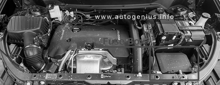
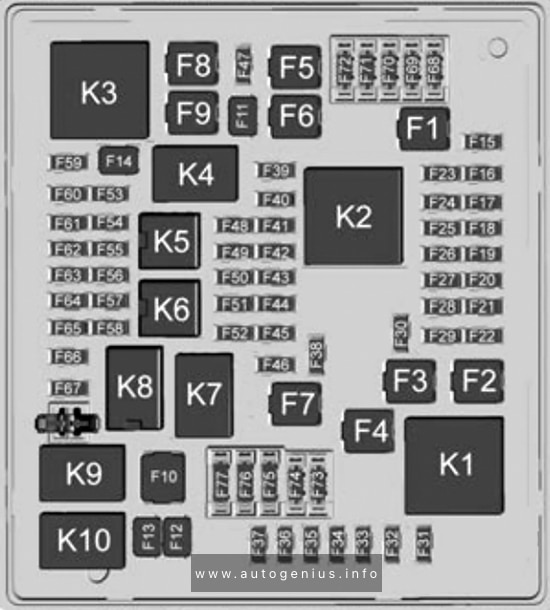
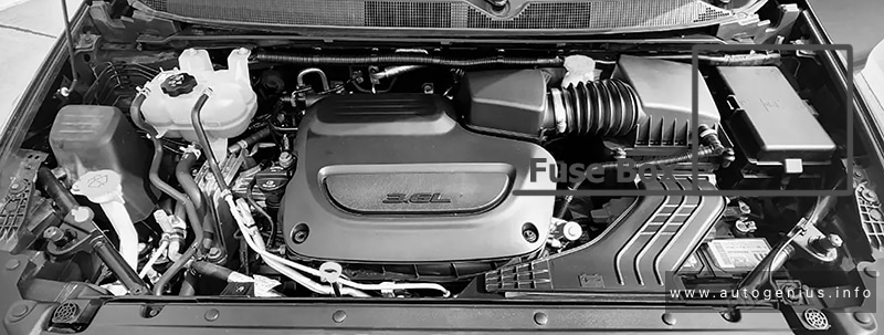
Engine compartment fuse box
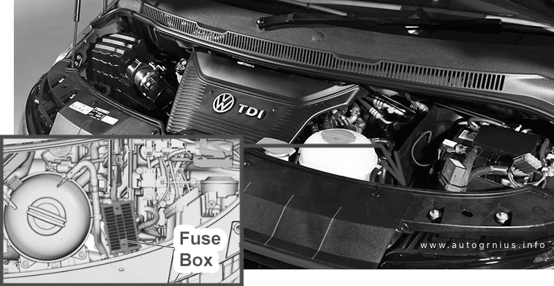
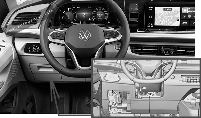
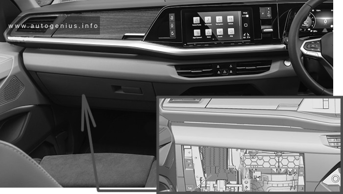
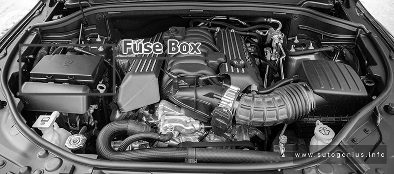
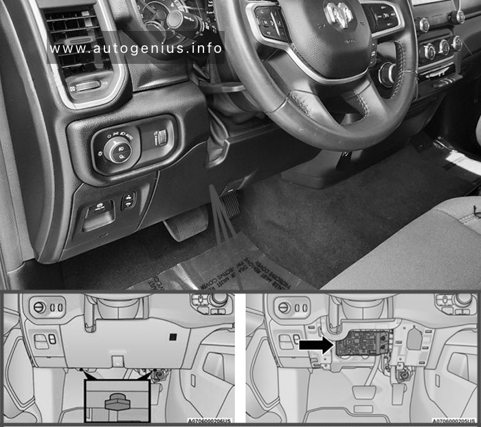
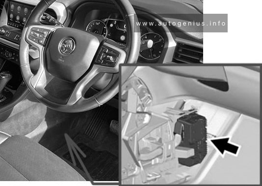
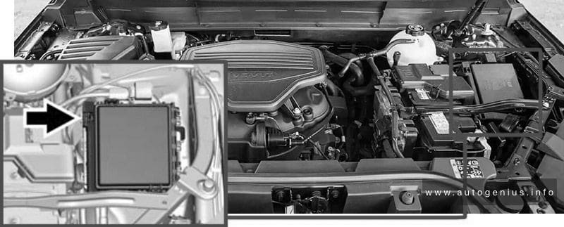
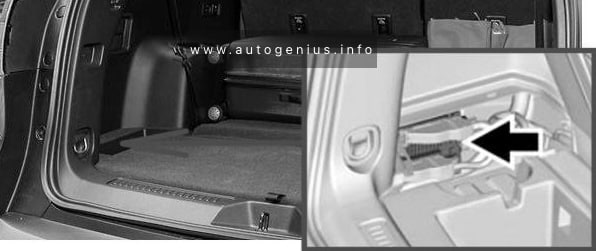
Fuse Box Location
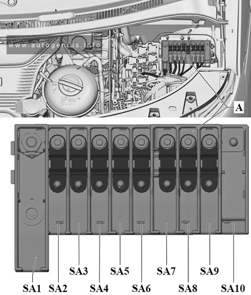
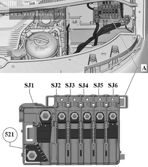
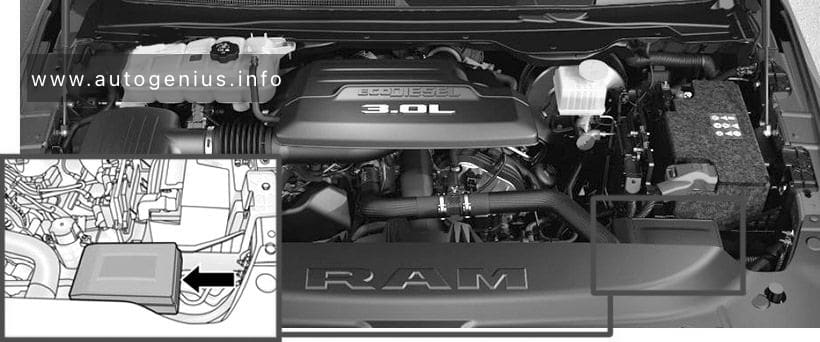
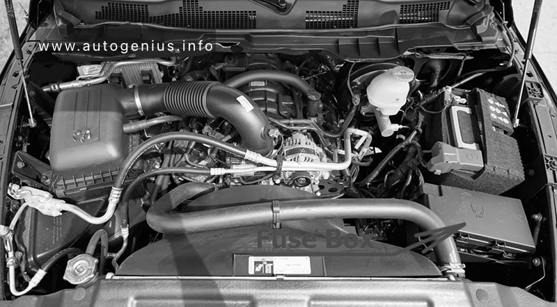
The Power Distribution Center (PDC) is located in the engine compartment near the battery. Remove the cover by unlatching the two locks located at each side of the PDC cover, avoid using screwdrivers or any other tool to remove the cover, since they may apply excessive force and result in a broken/damaged part.
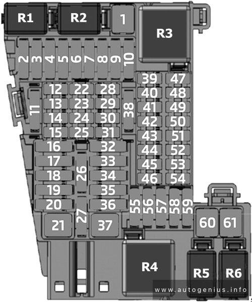
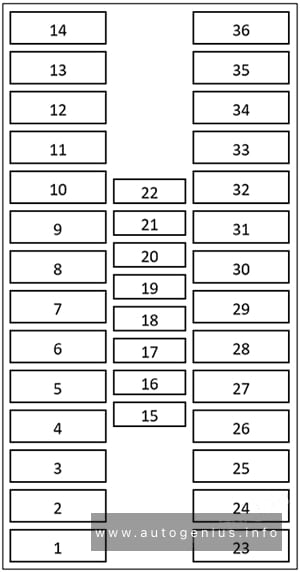
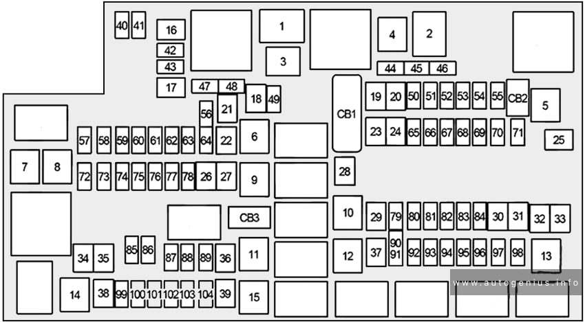
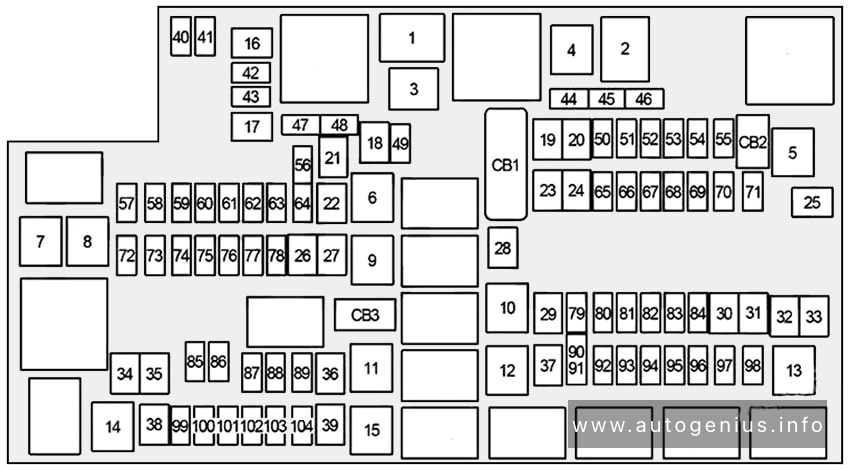
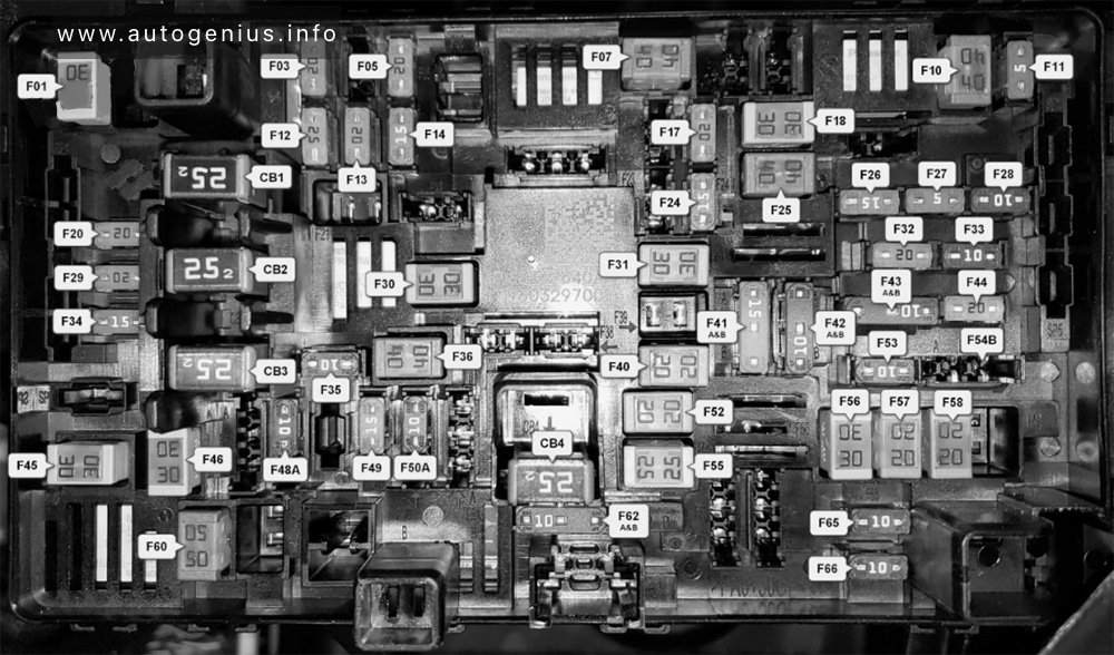
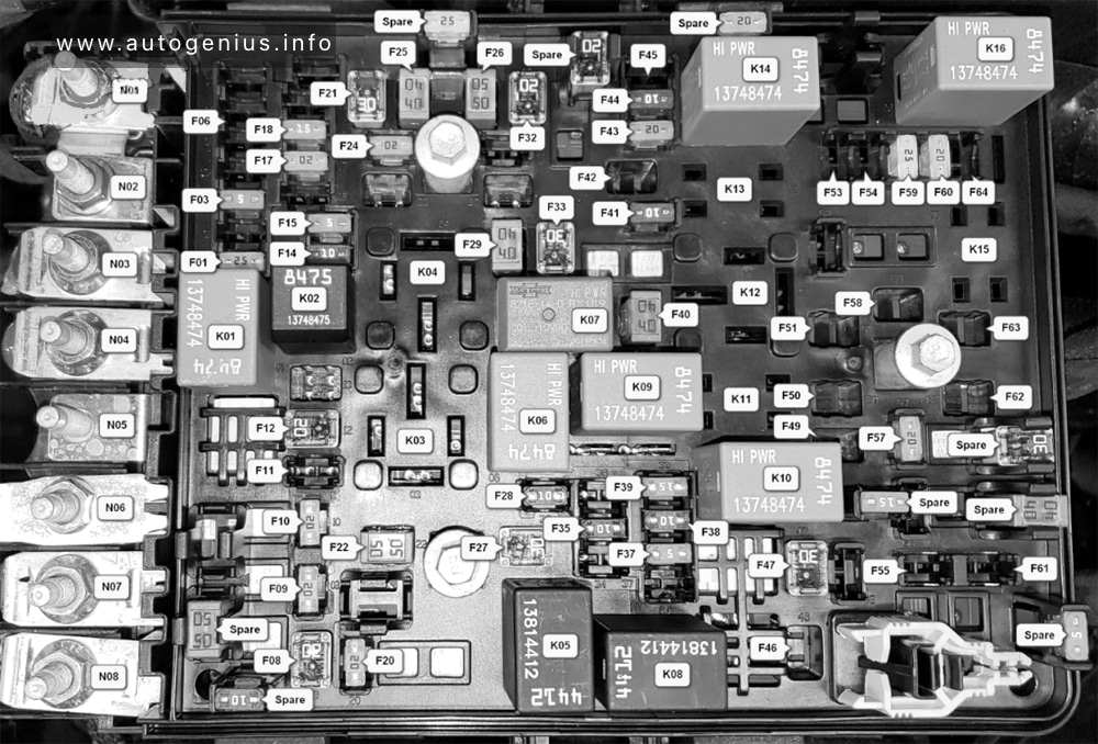
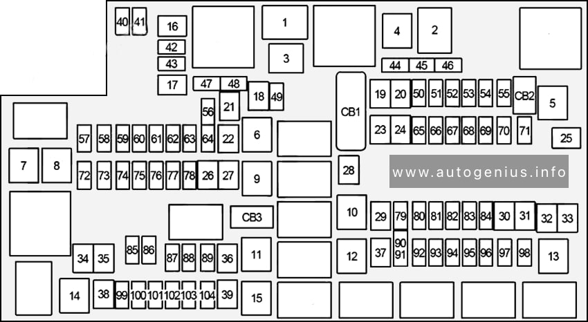
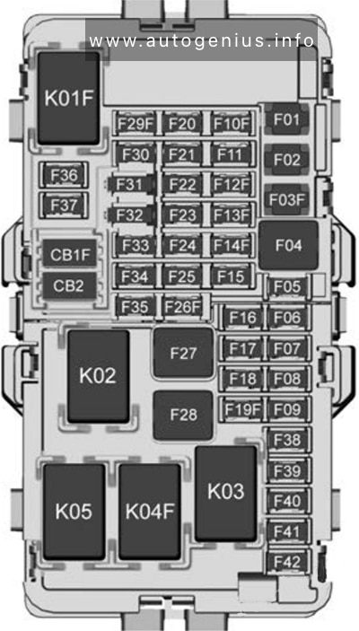
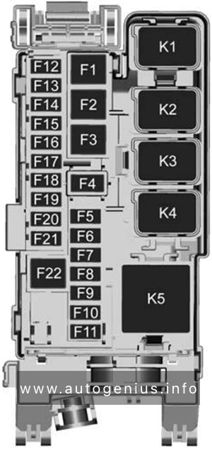
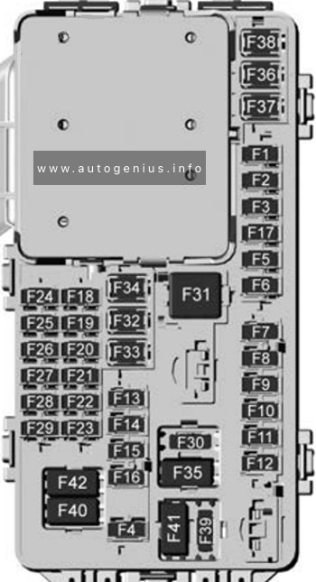
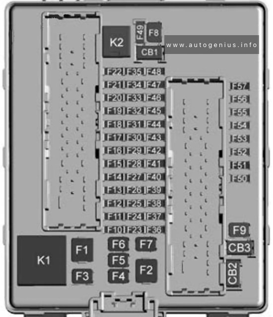
Fuse Box Diagram
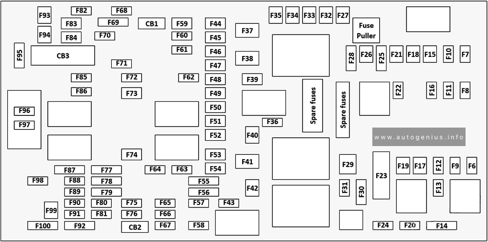
Assignment of the fuses in the PDC (2020-2024)
| № | Amps | Description |
|---|---|---|
| F06 | – | Not Used |
| F07 | 25A Clear | Ignition Coil / Fuel Injector |
| F08 | – | Not Used |
| F09 | 25A Clear | Amplifier / Active Noise Control |
| F10 | – | Not Used |
| F11 | – | Not Used |
| F12 | 5A Tan | Battery Sensor (IBS) |
| F13 | 10A Red | 2020-2021: ECM (ESS Only) 2022-2024: ECM (S) |
| F14 | 10A Red | ECM |
| F15 | 40A Green | CBC Feed #3 (Power Locks) |
| F16 | 20A Yellow | ECM |
| F17 | 30A Pink | Starter |
| F18 | 40A Green | CBC Feed #4 (Exterior Lighting #1) |
| F19 | 25A Clear | 2nd Row Folding Seats Solenoid LT |
| F20 | 10A Red | A/C Compressor Clutch |
| F21 | 25A Clear | 2nd Row Folding Seat Solenoid RT |
| F22 | – | Not Used |
| F23 | – | Not used |
| F24 | 20A Yellow | RR Wiper |
| F25A | 10A Red | 2020-2021: Handsfree LT & RT RR Door Release Mod |
| F25B | 10A Red | 2020-2021: Active Grill Shutter / PWR Mirror |
| F25 | 10A Red | 2022-2024: Hands-free Door Mod / Active Grill Shutter / PWR Mirror / VRM |
| F26 | 40A Green | Front HVAC Blower Motor |
| F27 | 25A Clear | RR Slide Door Module – RT |
| F28A | 10A Red | 2020-2021: Diagnostic Report |
| F28B | 10A Red | 2020-2021: USB + AUX Port / Video USB Port |
| F28 | 10A Red | 2022-2024: Diagnostic Port / USB+ (IP) / Video USB Port / Overhead DVD Player (Aftermarket) |
| F29 | – | Not Used |
| F30A | 15A Blue | 2020-2021: Media HUB 1&2 |
| F30B | 15A Blue | 2020-2021: PWR Lumbar SW |
| F30 | 15A Blue | 2022-2024: Media HUB / PWR Lumbar |
| F31 | – | Not Used |
| F32 | 20A Blue | ECM |
| F33 | 30A Pink | Power Liftgate Module |
| F34 | 25A Clear | RR Door Module – LT |
| F35 | 25A Clear | Sunroof Control Module |
| F36 | – | Not Used |
| F37 | 40A Green | 2020-2021: CBC Feed #4 (Exterior Lighting #2) 2022-2024: CBC / Exterior Lights |
| F38 | 60A Yellow | Vacuum Cleaner |
| F39 | 25A Clear | Rear HVAC Blower Motor |
| F40 | – | Not Used |
| F41 | – | Not Used |
| F42 | 40A Green | Folding Seat Module |
| F43 | 20A Yellow | Fuel Pump Motor |
| F44 | 30A Pink | 2020-2021: CBC Feed #1 (Interior Lights) 2022-2024: CBC / Interior Lights |
| F45 | 30A Pink | Power Inverter |
| F46 | 30A Pink | Driver Door Module |
| F47 | 30A Pink | Passenger Door Module |
| F48 | – | Not Used |
| F49 | 25A Clear | RR Sliding Door Module – LT |
| F50 | 25A Clear | RR Door Module – RT |
| F51 | 30A Pink | Front Wiper |
| F52 | 30A Pink | Brake Vacuum Pump |
| F53 | – | Not Used |
| F54 | 40A Green | ESP-ECU And Valves |
| F55A | 15A Blue | 2020-2021: Radio Frequency HUB / Keyless Ignition System (KIN) / (Electronic Steering Lock-BUX ONLY) |
| F55B | 15A Blue | 2020-2021: DVD / Video Routing Module (VRM |
| F55 | 15A Blue | 2022-2024: RF HUB/ KIN / ESL / DVD |
| F56A | 10A Red | 2020-2021: Front and Rear HVAC Control Module / Occupant Classification Module (OCM) / Electronic Steering Lock (ESL) |
| F56B | 10A Red | 2020-2021: ESP/ESC |
| F56 | 10A Red | 2022-2024: Front & Rear HVAC Control / OCM / ESL / ESP / ESC |
| F57 | – | Not Used |
| F58 | 10A Red | Drive Train Control Mod / Power Transfer Unit – If Equipped |
| F59 | 30A Pink | Trailer Tow Receptacle – If Equipped |
| F60 | 20A Yellow | Rear Cargo APO |
| F61 | 20A Yellow | Trailer Tow Right Stop/Turn – If Equipped |
| F62 | – | Not Used |
| F63 | 20A Yellow | Trailer Tow Left Stop/Turn – If Equipped |
| F64 | 15A Blue | RT HID Headlamp |
| F65 | – | Not Used |
| F66 | 15A Blue | 2020-2021: Instrument Panel Cluster (IPC) / SGW 2022-2024: Cluster |
| F67 | 10A Red | Haptic Lane Feedback Module (HALF) / Parktronics System (PTS) / Drivers Assist System Module (DASM) |
| F68 | – | Not Used |
| F69 | – | Not Used |
| F70 | – | Not Used |
| F71 | 20A Yellow | Horn |
| F72 | 10A Red | Heated Mirrors – If Equipped |
| F73 | 30A Pink | Rear Defroster (EBL) |
| F74 | 20A Blue | Trailer Tow Backup |
| F75 | 5A Tan | Overhead Console / RR ISC |
| F76 | 20A Yellow | Uconnect / Center Display / Telematics |
| F77A | 10A Red | 2020-2021: RR Entertainment Screen 1 & 2 / Media HUB 1 & 2 / 3rd Row USB Charge 0nly / 2nd Row USB Charge Only / Vaccum Cleaner SW / 3rd Row Recline ST SW / LT & RT Stow N Go SW / LT & RT Sliding Door SW Backlight |
| F77B | 10A Red | 2020-2021: Rain Sensor / Sunroof / CRVMM |
| F77 | 10A Red | 2022-2024: RR Entertainment / Media Hub / USB (S) / Rain Sensor / Sunroof / RR View Mirror / Overhead DVD Player / Int Monitoring Camera / Wireless Charging Pad |
| F78A | 15A Blue | 2020-2021: Transmission Control Module (TCM) / E-Shifter |
| F78B | 15A Blue | 2020-2021: Instrument Cluster |
| F78 | 15A Blue | 2022-2024: TCM (ZF) / E-Shifter / Cluster |
| F79 | 10A Red | 2020-2021: ICS / Front And Rear HVAC / SCCM / EPB 2022-2024: ICS / HVAC / EPB SW / Strg Column Cntrl |
| F80 | – | Not Used |
| F81 | – | Not Used |
| F82 | – | Not Used |
| F83 | 20A Blue | TT Park Lights – If Equipped |
| 30A Pink | Headlamp Washer Pump – If Equipped | |
| F84 | 30A Pink | Drive Train Control MOD – If Equipped |
| F85 | 20A Yellow | Cigar Lighter |
| F86 | – | Not Used |
| F87 | – | Not Used |
| F88 | 20A Yellow | Front Heated Seats |
| F89 | 20A Yellow | Rear Heated Seats |
| F90 | – | Not Used |
| F91 | 15A Blue | Front Ventilated Seats / Heated Steering Wheel |
| F92 | 5A Tan | Security Gateway |
| F93 | – | Not Used |
| F94 | 40A Green | ESC Motor Pump |
| F95A | 10A Red | USB Charge Port – ACC RUN |
| F95B | 10A Red | Selectable Fuse Location – USB IP (Direct) B+ |
| F96 | 10A Red | Occupant Restraint Controller (ORC) (Airbag) |
| F97 | 10A Red | Occupant Restraint Controller (ORC) (Airbag) |
| F98 | 15A Blue | Left HID Headlamp |
| F99 | 30A Pink | Trailer Tow Module – If Equipped |
| F100A | 10A Red | 2020-2021: AHLM |
| F100B | 10A Red | 2020-2021: Rear Camera / LBSS / RBSS / CVPM / Humidity Sensor / ln Vehicle Temperature Sensor |
| F100 | 10A Red | 2022-2024: Headlamp Level / RR Camera / Blindspot / Humidity Snsr / In Car Temp Snsr / Headlamp SW |
| CB1 | 25A Circuit Breaker | Power Seats (Driver) |
| CB2 | 25A Circuit Breaker | Power Seats (Pass) 30 Amp mini fuse is substituted for 25 Amp Circuit Breaker. |
| CB3 | 25A Circuit Breaker | FRT PWR Window W/O Door Nodes + RR PWR Window Lockout |
WARNING: Terminal and harness assignments for individual connectors will vary depending on vehicle equipment level, model, and market.