MG eHS (2020 – 2023) – fuse and relay box diagram
Years of production: 2020, 2021, 2022, 2023
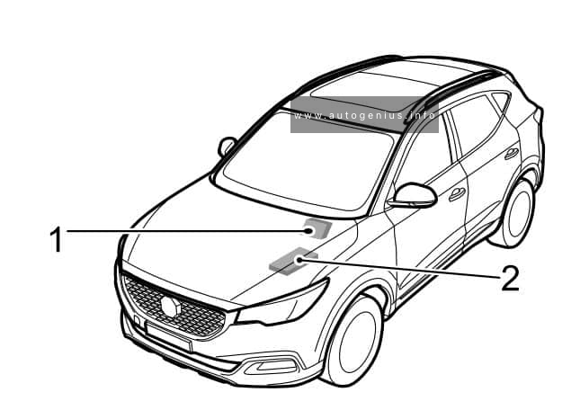
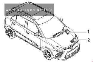
The MG eHS (also known as the HS PHEV), a compact plug-in hybrid crossover, has been available since 2020. This article provides fuse box diagrams for the 2020, 2021, 2022, and 2023 models, offers information on the locations of the fuse panels inside the vehicle, and explains the function of each fuse (fuse layout).
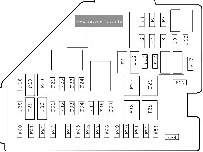
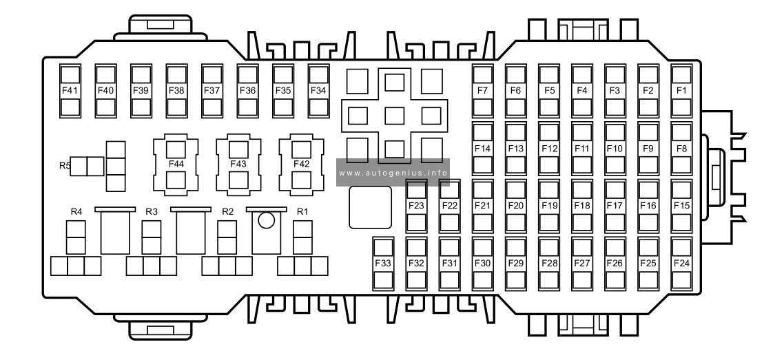
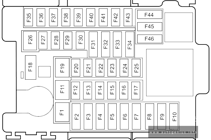
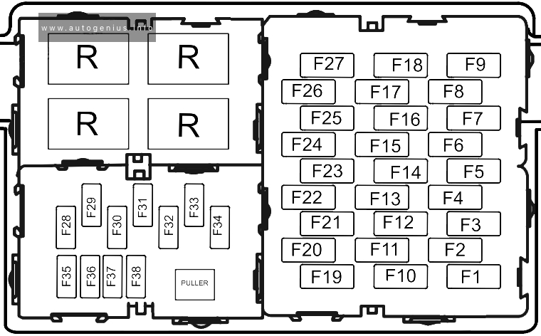
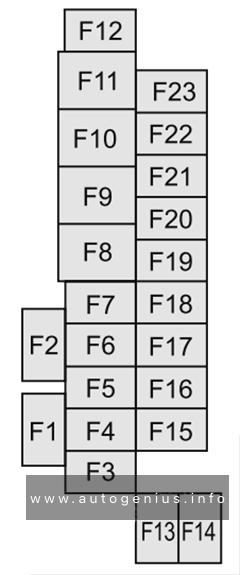
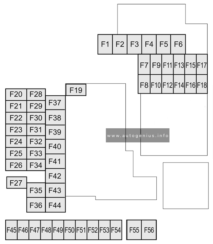
Passenger Compartment Fuse Box
Fuse Box Diagram

Assignment of the fuses in the passenger compartment
| No. | A | Protected components |
| F1 | 10A | Sensing Diagnostic Module (Airbag), Electronic Shifter Control Unit, TBOX, Instrument Pack, Body Control Module, Airbag Display Module |
| F2 | 7.5A | Engine Control Module, Hybrid Control Unit |
| F3 | 5.0A | Front View Control Module, Front Detection Radar |
| F6 | – | – |
| F7 | 15A | Towing Kit Connector Socket |
| F8 | 15A | Front Power Socket |
| F9 | 5A | USB Port |
| F10 | – | – |
| F11 | 7.5A | Mirror Heaters |
| F12 | 25A | Rear Windscreen Heating |
| F13-F14 | – | – |
| F17 | – | – |
| F18 | 30A | Rear Left Window Lift |
| F19 | 5A | EPB Switch, PRND Display |
| F20 | 30A | Rear Right Window Lift |
| F21 | 10A | Front Right Seat Heating Relay |
| F22 | 5A | Diagnostic Line Connector |
| F23 | 10A | Front Left Seat Heating Relay |
| F24 | 10A | Gateway |
| F25 | 40A | KLR Relay |
| F26 | 30A | Passenger Window lift |
| F27 | – | – |
| F28 | 5A | Passive Entry Passive Start Module, Backup Immobilizer Coil |
| F29 | 10A | Gateway |
| F30 | 5A | Driver Door Switch Pack, Rain Light Sensor |
| F31 | – | – |
| F32 | 5A | Ambient Light Control Module |
| F33 | 5A | Sensing Diagnostic Module (Airbag) |
| F34 | 5A | TBOX |
| F35 | 10A | Radio Broadcasting Reception Module |
| F36 | 10A | Electronic Steering Column Lock |
| F37 | 20A | Driver Electric Adjust Seat Switch |
| F38 | 30A | Driver Window Lift |
| F39 | 30A | Blower |
| F40 | 15A | Entertainment System |
| F41 | 5A | Upper Console Switch |
| F42 | 10A | AC Control Module |
| F43 | 5A | Instrument Pack |
| F44 | 5A | Rear Driving Assistance System |
| F45 | 30A | Sunroof Motor |
| F46 | 5A | Tyre Pressure Monitoring System |
| F47 | 30A | Sunshade Motor |
| F48 | 20A | Passenger Electric Adjust Seat |
| F49 | 5A | Around View Module |
| F50 | – | – |
| F51 | 30A | Rear Windscreen Heating Relay, Exterior Mirrors Relay |
| F52 | 10A | Headlamp, Interior Rear View Mirror, Headlamp Levelling Switch |
| F53 | 10A | Electronic Shifter Control Unit |
| F54 | – | – |
| F54 | – | – |
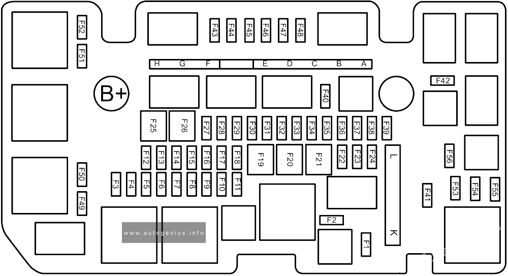
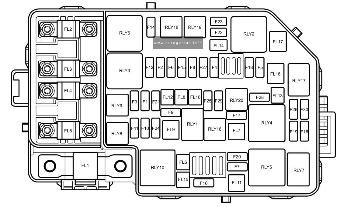
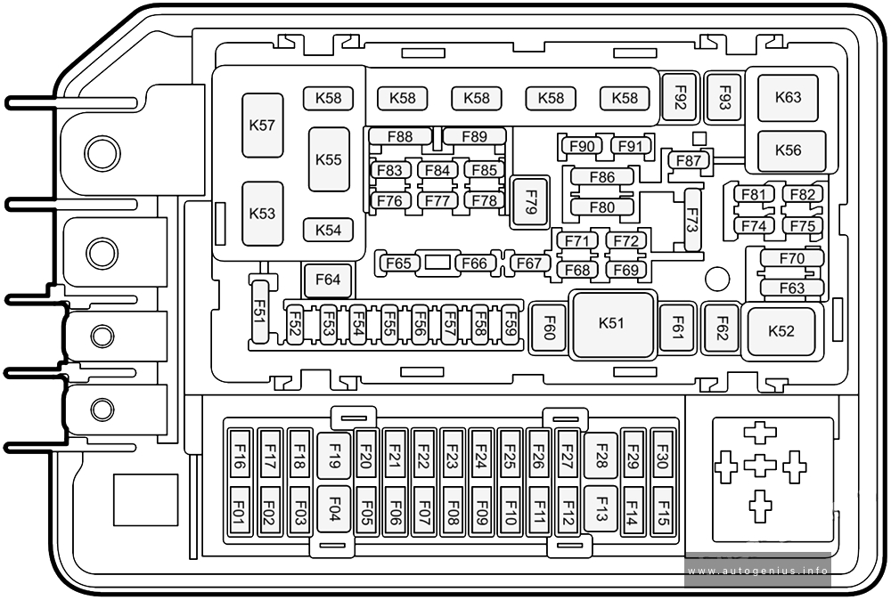
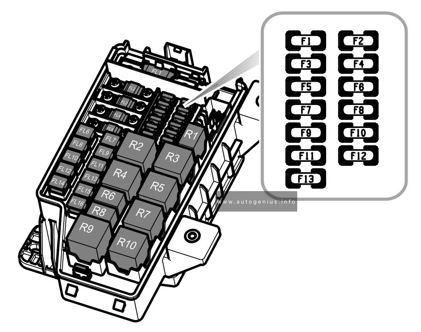
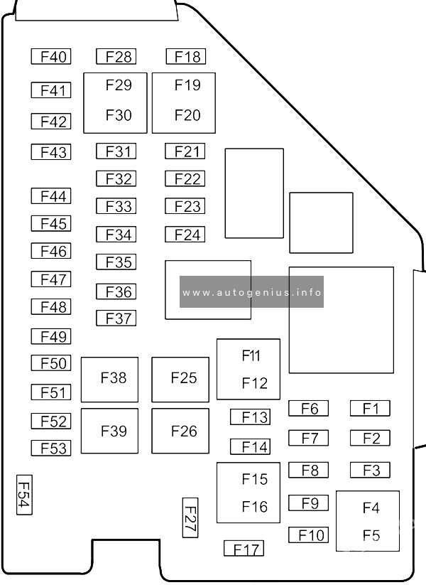
Engine Compartment Fuse Box
Fuse Box Diagram
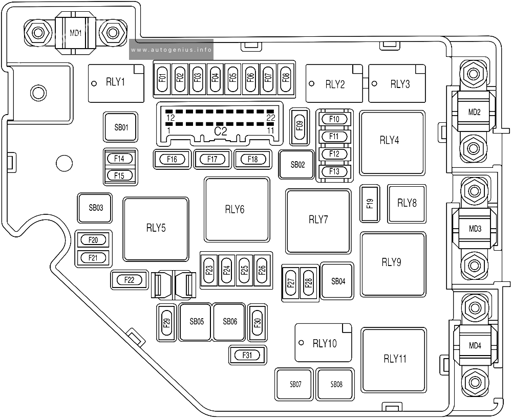
Assignment of the fuses in the engine compartment
| No. | A | Protected components |
| F01 | 10A | Right Headlamp Assembly |
| F02 | 10A | Left Headlamp Assembly |
| F03 | 10A | DC/DC Convertor |
| F04 | – | – |
| F05 | 5A | Electric Air Conditioning Compressor |
| F06 | – | – |
| F07 | – | – |
| F08 | 20A | Power Electronic Box Coolant Pump |
| F09 | 10A | Fuel Pump Relay, Lower Console Switch, Fuel Tank Isolation Diagnosis Module (Tank Leakage), Brake Pedal Switch |
| F10 | 20A | Engine Control Module |
| F11 | 15A | Intake Variable Camshaft Timing, Exhaust Variable Camshaft Timing, Upstream Lambda Sensor, Downstream Lambda Sensorv Canister Purge Valve |
| F12 | 20A | Ignition Coil |
| F13 | 15A | Waste Gate Control Valve, Dump Valve, Electronic Thermostat, Mass Air Flow Sensor |
| F14 | 25A | Body Control Module |
| F15 | 10A | Rear Washer Relay |
| F16 | 25A | Body Control Module |
| F17 | 25A | Body Control Module |
| F18 | 25A | Body Control Module |
| F19 | 10A | Front Fog Lamp Relay |
| F20 | 10A | Front Washer Relay |
| F21 | 10A | Engine Control Module |
| F22 | 10A | Power Electronic Box |
| F23 | – | – |
| F24 | – | – |
| F25 | 30A | Hybrid Control Unit |
| F26 | 25A | Body Control Module |
| F27 | – | – |
| F28 | 10A | Engine Auxiliary Pump |
| F29 | 15A | Horn |
| F30 | 10A | Hybrid Control Unit |
| F31 | 25A | Front Wiper Enable Relay |
| SB01 | 25A | Body Control Module |
| SB02 | 60A | Cooling Fan Low Speed Relay |
| SB03 | 40A | EVP Relay |
| SB04 | 40A | Cooling Fan |
| SB05 | 40A | Stability Control System-Pump |
| SB06 | 40A | Stability Control System-Valve |
| SB07 | – | – |
| SB08 | 50A | Cooling Fan Middle Speed Relay |
| MD1 | 200A | Power Pump |
| MD2 | 100A | Passenger Compartment Fusebox |
| MD3 | 80A | Electric Power Steering Module |
| MD4 | 200A | Luggage Compartment Fusebox |
WARNING: Terminal and harness assignments for individual connectors will vary depending on vehicle equipment level, model, and market.