Year of production: 2009, 2010, 2011, 2012, 2013, 2014
This article focuses on the seventh-generation Suzuki Alto, manufactured between 2009 and 2014. It includes fuse box diagrams for the 2009 to 2014 models, provides details on the location of the fuse panels within the vehicle, and explains the function of each fuse (fuse layout).
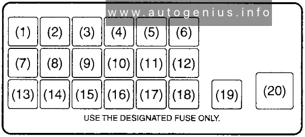
Passenger Compartment Fuse Box
Fuse Box Location
The fuse box is located under the driver’s side of the dashboard.
Seat Leon (mk4; 2021 – 2025) – fuse and relay box diagram
Year of production: 2021, 2022, 2023, 2024, 2025
This article covers the fourth-generation SEAT Leon (KL1/KL8), produced from 2020 onward. It includes fuse box diagrams for the 2021, 2022, 2023, 2024 and 2025 models, details the locations of the fuse panels within the vehicle, and provides information on the function of each fuse (fuse layout).
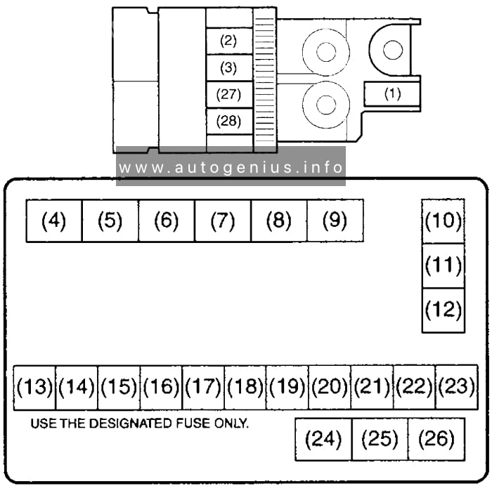
Passenger Compartment Fuse Box
Fuse Box Location
The fuse box is located behind the cover on the driver’s side.
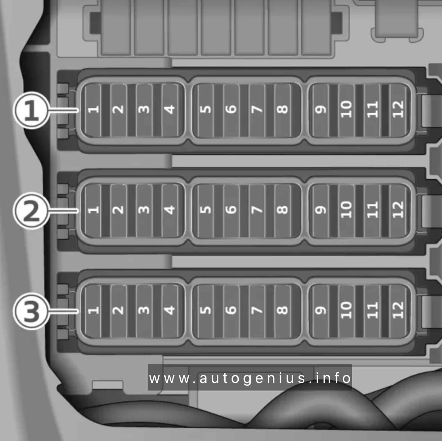
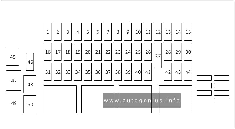
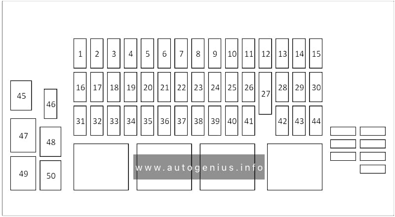
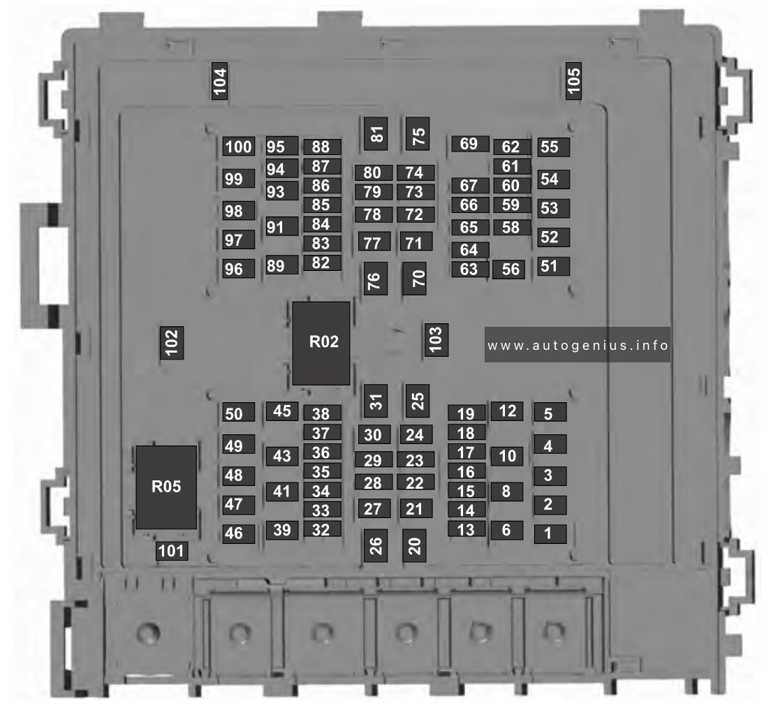
Fuse Box Diagram
Seat Leon (mk4; 2021 – 2025) – fuses and relay box diagram – passenger compartment
Assignment of the fuses in the instrument panel
№
Consumers
Amps
1
–
–
2
–
–
3
Trailer
25A
4
SCR, Adblue
20A
5
Automatic gearbox lever
25A
6
Interior light
30A
7
Heated seats
30A
8
Sunroof
20A
9
Left door
30A
11
Trailer
15A
12
Right lights
40A
13
Central locking
40A
14
External Ethernet Amplifier
30A
15
–
–
16
Airbag
7.5A
17
SCR, engine relay, 1.5
10A
18
KESSY (keyless locking)
7.5A
19
Instrument panel
7.5A
20
Connectivity Box
7.5A
21
Rear camera
7.5A
22
–
–
23
–
–
24
4×4 Haldex Control Unit
15A
25
RGS+EBSS front seat belts
25A
26
Right door
30A
27
RGS+EBSS front seat belts
25A
28
PHEV, Switching off the high voltage system for rescue tasks, Identified by a yellow label
10A
29
Trailer
15A
30
Radio
30A
31
Trailer
25A
32
–
–
33
–
–
34
230V socket
30A
35
Left lights
40A
36
Air conditioner fan
40A
37
Electric rear lid
30A
38
–
–
39
Heated steering wheel
10A
40
Alarm horn
7.5A
41
Gateway
7.5A
42
Automatic gearbox lever
7.5A
43
Air conditioning and heating control panel, rear window heating, AC compressor
Audi e-tron GT (2021 – 2025) – fuse and relay box diagram – US version
Year of production: 2021, 2022, 2023, 2024, 2025
The Audi e-tron GT, a battery-electric executive car, has been in production since 2020. In this article, you’ll find fuse box diagrams for the 2021, 2022, 2023, 2024 and 2025 models. You’ll also learn where the fuse panels are located within the vehicle and find detailed information on the fuse assignments (fuse layout).
Passenger compartment
Fuse box location
The fuses are located in the left and right footwells, as well as at the left and right front sides of the cockpit.
Left footwell fuse panel
Fuse Box Diagrams
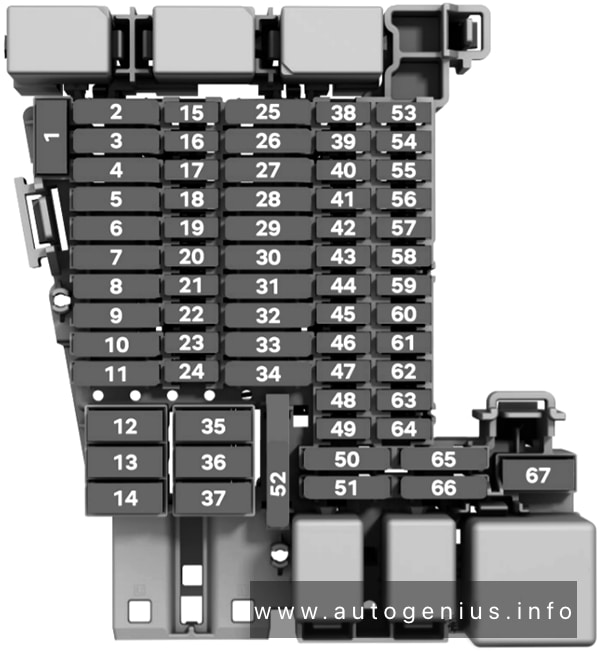
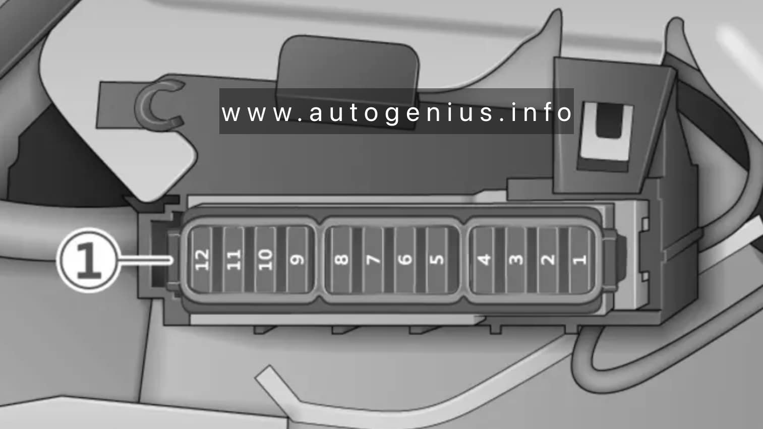
Audi e-tron GT (2021 – 2025) – fuses and relay box diagram – passenger compartment (left footwell)
Assignment of the fuses in the left footwell
№
Equipment
Fuse panel 1 (brown)
1
Heating circuit coolant pump
3
Thermal management
5
Vehicle electrical system control module
6
Vehicle electrical system control module
7
Light/rain/humidity sensor
8
Remote controlled parking
9
Roof electronics control module
10
Vehicle electrical system control module
12
Data exchange and telematics control module
Fuse panel 2 (red)
1
Driver assistance systems control module
2
Left rear door control module
3
Thermal management
4
Windshield wipers
5
Electronic Stabilization Control (ESC)
7
Left front safety belt
8
Vehicle electrical system control module
9
Vehicle electrical system control module
10
Left headlight
11
Left front door control module
12
Vehicle electrical system control module
Fuse panel 3 (white)
3
Vehicle electrical system control module
4
Diagnostic connection
6
Left front intersection assistant
7
Brake system pressure reservoir
8
Rearview mirror
9
Data exchange and telematics control module
10
Power supply
11
Power supply
Right footwell fuse panel
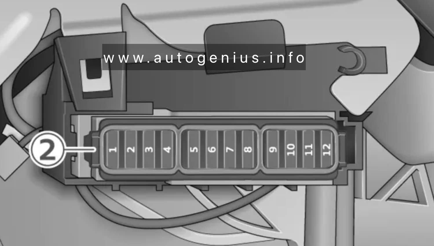
Fuse Box Diagrams
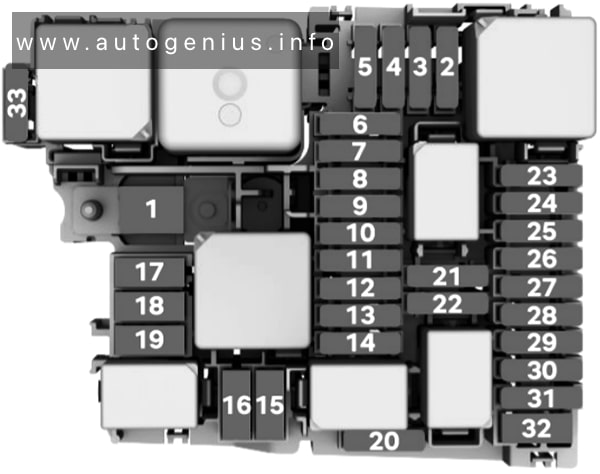
Audi e-tron GT (2021 – 2025) – fuses and relay box diagram – passenger compartment (right footwell)
Assignment of the fuses in the right footwell
№
Equipment
Fuse panel 4 (brown)
1
Vehicle electrical system control module
3
Vehicle electrical system control module
4
Windshield wipers
5
Vehicle electrical system control module
6
Right rear door control module
7
Driver assistance systems control module
8
Right front door control module
9
Airbag control module
10
Right front safety belt
11
Remote controlled parking
12
Vehicle electrical system control module
Fuse panel 5 (red)
1
Diagnostic interface
3
Thermal management
4
Right headlight
5
Vehicle electrical system control module
6
Vehicle electrical system control module
7
Night vision assist control module
8
Driver assistance systems front camera
9
Rear climate control system control panel
11
Right front intersection assistant
Fuse panel 6 (white)
1
Diagnostic connection
2
Diagnostic interface
3
Brake system pressure reservoir
4
Vehicle electrical system control module
5
Front power electronics control module
6
Ionizer
7
Power supply
8
Power supply
9
Voltage converter
10
Power steering
12
Adaptive cruise assist
Left cockpit fuse panel
Fuse Box Diagrams
Audi e-tron GT (2021 – 2025) – fuses and relay box diagram – passenger compartment (left cocpit)
Jaguar E-Pace (X540; 2021) – fuse and relay box diagram
Year of production: 2021
The Jaguar E-Pace (X540), a subcompact luxury crossover SUV, has been in production since 2017. In this article, you’ll find fuse box diagrams for the 2021 models, along with details on the locations of the fuse panels within the vehicle and explanations of each fuse’s function and layout.
The Jaguar E-Pace (X540), a subcompact luxury crossover SUV, has been in production since 2017. In this article, you’ll find fuse box diagrams for the 2017 through 2020 models, along with details on the locations of the fuse panels within the vehicle and explanations of each fuse’s function and layout.
Ford F-750 (2024 – 2025) – fuse and relay box diagram
Year of production: 2024, 2025
This article focuses on the facelifted eighth-generation Ford F-650 and F-750, produced from 2021 to the present. It includes fuse box diagrams for the 2024 and 2025 models, provides information on the locations of the fuse panels within the vehicle, and outlines the function and layout of each fuse.
Passenger compartment
Fuse box location
The fuse panel is in the passenger footwell. Remove the panel cover to access the fuses.
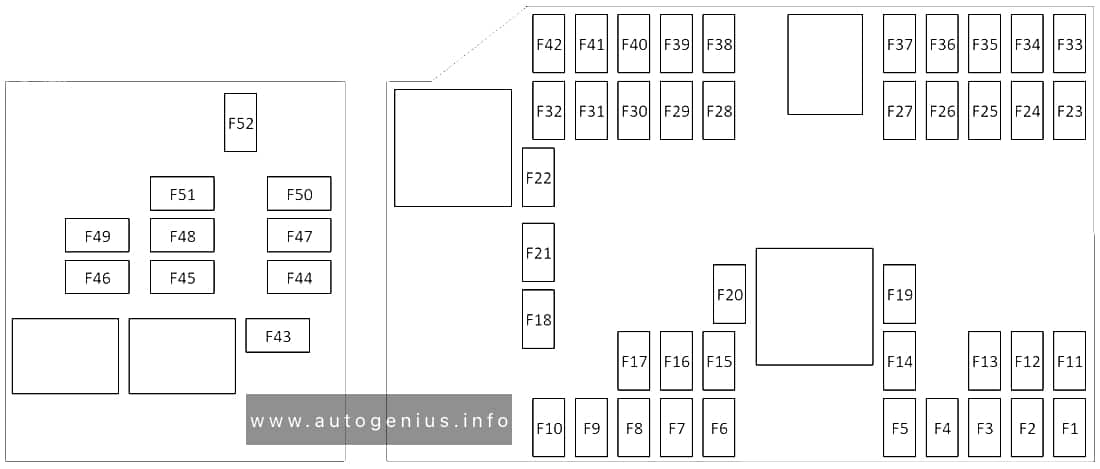
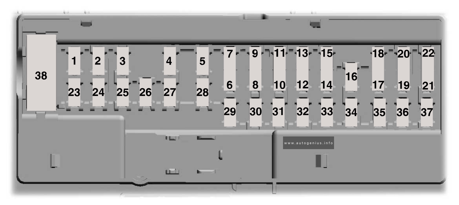
Fuse Box Diagrams
Ford F-750 (2024 – 2025) – fuses and relay box diagram – passenger compartment
Assignment of the fuses in the passenger compartment fuse box
№
Rating
Protected Component
1
—
Not used.
2
10 A
Right-hand and left-hand front door lock switch, Telescopic mirror switch, Right-hand and left-hand front window switch (two window units), Right-hand and left-hand front window motor. Inverter.
3
7.5 A
Power mirror switch.
4
20 A
Ancillary translator module.
5
—
Not used.
6
—
Not used.
7
10 A
Smart data link connector power, Air brake diagnostic connector.
8
—
Not used.
9
—
Not used.
10
—
Not used.
11
—
Not used.
12
7.5 A
Smart data link connector.
13
7.5 A
Instrument Cluster, Steering column control module.
14
—
Not used.
15
15 A
Climate control module.
16
—
Not used.
17
—
Not used.
18
7.5 A
Yaw sensor, Electronic stability control and non-electric stability control.
19
5 A
Telematics control unit module.
20
5 A
Ignition switch.
21
—
Not used.
22
—
Not used.
23
30 A
Left-hand front window motor.
24
—
Not used.
25
—
Not used.
26
30 A
Right-hand front motor window.
27
—
Not used.
28
—
Not used.
29
15 A
Relay folding mirror.
30
5 A
Brake signal for air brake, Customer access stop lamp signal, Brake on-off isolation relay, Trailer tow stop lamp relay.
31
10 A
Upfitter interface module, Remote radio frequency receiver.
32
20 A
Radio.
33
—
Not used.
34
—
Not used.
35
5 A
Tow haul switch.
36
15 A
Lane departure warning camera, Mirror display
37
—
Not used.
38
30 A
Left-hand front power window switch (four window units).
Engine Compartment Fuse Box
Fuse Box Diagrams
Ford F-750 (2024 – 2025) – fuses and relay box diagram – engine compartment
Assignment of the fuses in the engine compartment fuse box
№
Rating
Protected Component
1
20 A
Horn.
2
40 A
Blower motor.
Blower motor control.
3
20 A
Upfit – frame.
4
30 A
Starter motor.
5
—
Not used.
6
20 A
Upfitter relay 4.
8
—
Not used.
10
—
Not used.
12
—
Not used.
13
10 A
Run/start spare. rear view camera.
14
10 A
Adaptive cruise control.
15
10 A
Blower motor relay.
16
20 A
Air dryer.
17
10 A
Powertrain control module – ignition status run power, Glow plug control module – ignition status run power (diesel).
18
10 A
Anti-lock brake system run/start.
19
10 A
Transmission control module – Ignition status run power (diesel).
Ford F-650 (2024 – 2025) – fuse and relay box diagram
Year of production: 2024, 2025
This article focuses on the facelifted eighth-generation Ford F-650 and F-750, produced from 2021 to the present. It includes fuse box diagrams for the 2024 and 2025 models, provides information on the locations of the fuse panels within the vehicle, and outlines the function and layout of each fuse.
Passenger compartment
Fuse box location
The fuse panel is in the passenger footwell. Remove the panel cover to access the fuses.
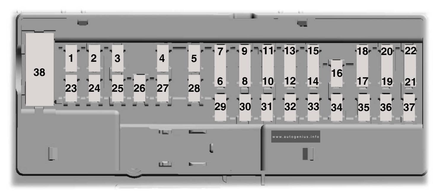
Fuse Box Diagrams
Ford F-650 (2024 – 2025) – fuses and relay box diagram – passenger compartment
Assignment of the fuses in the passenger compartment fuse box
№
Rating
Protected Component
1
—
Not used.
2
10 A
Right-hand and left-hand front door lock switch, Telescopic mirror switch, Right-hand and left-hand front window switch (two window units), Right-hand and left-hand front window motor. Inverter.
3
7.5 A
Power mirror switch.
4
20 A
Ancillary translator module.
5
—
Not used.
6
—
Not used.
7
10 A
Smart data link connector power, Air brake diagnostic connector.
8
—
Not used.
9
—
Not used.
10
—
Not used.
11
—
Not used.
12
7.5 A
Smart data link connector.
13
7.5 A
Instrument Cluster, Steering column control module.
14
—
Not used.
15
15 A
Climate control module.
16
—
Not used.
17
—
Not used.
18
7.5 A
Yaw sensor, Electronic stability control and non-electric stability control.
19
5 A
Telematics control unit module.
20
5 A
Ignition switch.
21
—
Not used.
22
—
Not used.
23
30 A
Left-hand front window motor.
24
—
Not used.
25
—
Not used.
26
30 A
Right-hand front motor window.
27
—
Not used.
28
—
Not used.
29
15 A
Relay folding mirror.
30
5 A
Brake signal for air brake, Customer access stop lamp signal, Brake on-off isolation relay, Trailer tow stop lamp relay.
31
10 A
Upfitter interface module, Remote radio frequency receiver.
32
20 A
Radio.
33
—
Not used.
34
—
Not used.
35
5 A
Tow haul switch.
36
15 A
Lane departure warning camera, Mirror display
37
—
Not used.
38
30 A
Left-hand front power window switch (four window units).
Engine Compartment Fuse Box
Fuse Box Diagrams
Ford F-650 (2024 – 2025) – fuses and relay box diagram – engine compartment
Assignment of the fuses in the engine compartment fuse box
№
Rating
Protected Component
1
20 A
Horn.
2
40 A
Blower motor.
Blower motor control.
3
20 A
Upfit – frame.
4
30 A
Starter motor.
5
—
Not used.
6
20 A
Upfitter relay 4.
8
—
Not used.
10
—
Not used.
12
—
Not used.
13
10 A
Run/start spare. rear view camera.
14
10 A
Adaptive cruise control.
15
10 A
Blower motor relay.
16
20 A
Air dryer.
17
10 A
Powertrain control module – ignition status run power, Glow plug control module – ignition status run power (diesel).
18
10 A
Anti-lock brake system run/start.
19
10 A
Transmission control module – Ignition status run power (diesel).
This article focuses on the facelifted eighth-generation Ford F-650 and F-750, produced from 2021 to the present. It includes fuse box diagrams for the 2023 models, provides information on the locations of the fuse panels within the vehicle, and outlines the function and layout of each fuse.
Passenger compartment
Fuse box location
The fuse panel is in the passenger footwell. Remove the panel cover to access the fuses.
Fuse Box Diagrams
Ford F750 (2023) – fuses and relay box diagram – passenger compartment
Assignment of the fuses in the passenger compartment fuse box
№
Rating
Protected Component
1
—
Not used.
2
10 A
Right-hand and left-hand front door lock switch.
Telescopic mirror switch.
Right-hand and left-hand front window switch (two window units).
Right-hand and left-hand front window motor. Inverter.
3
7.5 A
Power mirror switch.
4
20 A
Ancillary translator module.
5
—
Not used.
6
—
Not used.
7
10 A
Smart data link connector power.
Air brake diagnostic connector.
8
—
Not used.
9
—
Not used.
10
—
Not used.
11
—
Not used.
12
7.5 A
Smart data link connector.
Enterprise wired-in-device (2021).
13
7.5 A
Cluster.
Steering column control module.
14
—
Not used.
15
15 A
Climate control module.
16
—
Not used.
17
—
Not used.
18
7.5 A
Yaw sensor.
Electronic stability control and non-electric stability control.
19
5 A
Telematics control unit module.
20
5 A
Ignition switch.
21
—
Not used.
22
—
Not used.
23
30 A
Left-hand front window motor.
24
—
Not used.
25
—
Not used.
26
30 A
Right-hand front motor window.
27
—
Not used.
28
—
Not used.
29
15 A
Relay folding mirror.
30
5 A
Brake signal for air brake.
Customer access stop lamp signal.
Brake on-off isolation relay.
Trailer tow stop lamp relay.
31
10 A
Upfitter interface module.
Remote radio frequency receiver.
32
20 A
Radio.
33
—
Not used.
34
—
Not used.
35
5 A
Tow haul switch.
36
15 A
Lane departure warning camera.
37
—
Not used.
38
30 A
Left-hand front power window switch (four window units).
Engine Compartment Fuse Box
Fuse Box Diagrams
Ford F750 (2023) – fuses and relay box diagram – engine compartment
Assignment of the fuses in the engine compartment fuse box
№
Rating
Protected Component
1
20 A
Horn.
2
40 A
Blower motor.
Blower motor control.
3
20 A
Upfit – frame.
4
30 A
Starter motor.
5
—
Not used.
6
20 A
Upfitter relay 4.
8
—
Not used.
10
—
Not used.
12
—
Not used.
13
10 A
Run/start spare.
14
10 A
Adaptive cruise control.
15
10 A
Blower motor relay.
16
20 A
Air dryer.
17
10 A
Powertrain control module – ignition status run power.
Glow plug control module – ignition status run power (diesel).
18
10 A
Anti-lock brake system run/start.
19
10 A
Transmission control module.
Ignition status run power (diesel).
20
30 A
Windshield wiper motor.
21
—
Not used.
22
—
Not used.
23
10 A
Alternator 2 (dual alternator only).
24
40 A
Body control module run power 2 bus.
25
50 A
Body control module run power 1 bus.
26
—
Not used.
27
20 A
Body builder battery feed.
28
—
Not used.
29
10 A
Alternator 1 A-Line.
30
—
Not used.
31
60 A
Hydromax pump.
32
20 A
Powertrain control module.
33
20 A
Canister vent solenoid (gas).
Canister purge solenoid (gas).
Variable cam timing actuator 11 (gas).
Heated exhaust gas oxygen sensor (gas).
Urea tank power (diesel).
Exhaust gas recirculation cool bypass valve (diesel).
34
10 A
A/C clutch relay.
Customer access vehicle power 3 feed.
Variable oil pump (diesel).
Cooling fan (diesel).
Fan clutch (gas).
Exhaust brake switch (2022).
35
20 A
Coil on plug (gas).
Urea tank (diesel).
Glow plug controller (diesel).
Nitrogen oxide sensor control module (diesel).
Particulate matter sensor (diesel).
36
10 A
Fuel volume control value (diesel).
Fuel pressure regulator (diesel).
This article focuses on the facelifted eighth-generation Ford F-650 and F-750, produced from 2021 to the present. It includes fuse box diagrams for the 2023 models, provides information on the locations of the fuse panels within the vehicle, and outlines the function and layout of each fuse.
Passenger compartment
Fuse box location
The fuse panel is in the passenger footwell. Remove the panel cover to access the fuses.
Fuse Box Diagrams
Ford F650 (2023) – fuses and relay box diagram – passenger compartment
Assignment of the fuses in the passenger compartment fuse box
№
Rating
Protected Component
1
—
Not used.
2
10 A
Right-hand and left-hand front door lock switch.
Telescopic mirror switch.
Right-hand and left-hand front window switch (two window units).
Right-hand and left-hand front window motor. Inverter.
3
7.5 A
Power mirror switch.
4
20 A
Ancillary translator module.
5
—
Not used.
6
—
Not used.
7
10 A
Smart data link connector power.
Air brake diagnostic connector.
8
—
Not used.
9
—
Not used.
10
—
Not used.
11
—
Not used.
12
7.5 A
Smart data link connector.
Enterprise wired-in-device (2021).
13
7.5 A
Cluster.
Steering column control module.
14
—
Not used.
15
15 A
Climate control module.
16
—
Not used.
17
—
Not used.
18
7.5 A
Yaw sensor.
Electronic stability control and non-electric stability control.
19
5 A
Telematics control unit module.
20
5 A
Ignition switch.
21
—
Not used.
22
—
Not used.
23
30 A
Left-hand front window motor.
24
—
Not used.
25
—
Not used.
26
30 A
Right-hand front motor window.
27
—
Not used.
28
—
Not used.
29
15 A
Relay folding mirror.
30
5 A
Brake signal for air brake.
Customer access stop lamp signal.
Brake on-off isolation relay.
Trailer tow stop lamp relay.
31
10 A
Upfitter interface module.
Remote radio frequency receiver.
32
20 A
Radio.
33
—
Not used.
34
—
Not used.
35
5 A
Tow haul switch.
36
15 A
Lane departure warning camera.
37
—
Not used.
38
30 A
Left-hand front power window switch (four window units).
Engine Compartment Fuse Box
Fuse Box Diagrams
Ford F650 (2023) – fuses and relay box diagram – engine compartment
Assignment of the fuses in the engine compartment fuse box
№
Rating
Protected Component
1
20 A
Horn.
2
40 A
Blower motor.
Blower motor control.
3
20 A
Upfit – frame.
4
30 A
Starter motor.
5
—
Not used.
6
20 A
Upfitter relay 4.
8
—
Not used.
10
—
Not used.
12
—
Not used.
13
10 A
Run/start spare.
14
10 A
Adaptive cruise control.
15
10 A
Blower motor relay.
16
20 A
Air dryer.
17
10 A
Powertrain control module – ignition status run power.
Glow plug control module – ignition status run power (diesel).
18
10 A
Anti-lock brake system run/start.
19
10 A
Transmission control module.
Ignition status run power (diesel).
20
30 A
Windshield wiper motor.
21
—
Not used.
22
—
Not used.
23
10 A
Alternator 2 (dual alternator only).
24
40 A
Body control module run power 2 bus.
25
50 A
Body control module run power 1 bus.
26
—
Not used.
27
20 A
Body builder battery feed.
28
—
Not used.
29
10 A
Alternator 1 A-Line.
30
—
Not used.
31
60 A
Hydromax pump.
32
20 A
Powertrain control module.
33
20 A
Canister vent solenoid (gas).
Canister purge solenoid (gas).
Variable cam timing actuator 11 (gas).
Heated exhaust gas oxygen sensor (gas).
Urea tank power (diesel).
Exhaust gas recirculation cool bypass valve (diesel).
34
10 A
A/C clutch relay.
Customer access vehicle power 3 feed.
Variable oil pump (diesel).
Cooling fan (diesel).
Fan clutch (gas).
Exhaust brake switch (2022).
35
20 A
Coil on plug (gas).
Urea tank (diesel).
Glow plug controller (diesel).
Nitrogen oxide sensor control module (diesel).
Particulate matter sensor (diesel).
36
10 A
Fuel volume control value (diesel).
Fuel pressure regulator (diesel).
Ford F-750 (2021 – 2022) – fuse and relay box diagram
Year of production: 2021, 2022
This article focuses on the facelifted eighth-generation Ford F-650 and F-750, produced from 2021 to the present. It includes fuse box diagrams for the 2021 and 2022 models, provides information on the locations of the fuse panels within the vehicle, and outlines the function and layout of each fuse.
Passenger compartment
Fuse box location
The fuse panel is in the passenger footwell. Remove the panel cover to access the fuses.
Fuse Box Diagrams
Ford F-750 (2021 – 2022) – fuses and relay box diagram – passenger compartment
Assignment of the fuses in the Passenger Compartment Fuse Box
№
Rating
Protected Component
1
—
Not used.
2
10 A
Right-hand and left-hand front door lock switch.
Telescopic mirror switch.
Right-hand and left-hand front window switch (two window units).
Right-hand and left-hand front window motor. Inverter.
3
7.5 A
Power mirror switch.
4
20 A
Ancillary translator module.
5
—
Not used.
6
—
Not used.
7
10 A
Smart data link connector power.
Air brake diagnostic connector.
8
—
Not used.
9
—
Not used.
10
—
Not used.
11
—
Not used.
12
7.5 A
Smart data link connector.
Enterprise wired-in-device (2021).
13
7.5 A
Cluster.
Steering column control module.
14
—
Not used.
15
15 A
Climate control module.
16
—
Not used.
17
—
Not used.
18
7.5 A
Yaw sensor.
Electronic stability control and non-electric stability control.
19
5 A
2022: Telematics control unit module.
20
5 A
Ignition switch.
21
5 A
2021: Exhaust brake switch.
22
—
Not used.
23
30 A
Left-hand front window motor.
24
—
Not used.
25
—
Not used.
26
30 A
Right-hand front motor window.
27
—
Not used.
28
—
Not used.
29
15 A
Relay folding mirror.
30
5 A
Brake signal for air brake.
Customer access stop lamp signal.
Brake on-off isolation relay.
Trailer tow stop lamp relay.
31
10 A
Upfitter interface module.
Remote radio frequency receiver.
32
20 A
Radio.
33
—
Not used.
34
—
Not used.
35
5 A
Tow haul switch.
36
15 A
Lane departure warning camera.
37
—
Not used.
38
30 A
Left-hand front power window switch (four window units).
Engine Compartment Fuse Box
Fuse Box Diagrams
Ford F-750 (2021 – 2022) – fuses and relay box diagram – engine compartment
Assignment of the fuses in the Engine Compartment Fuse Box
№
Rating
Protected Component
1
20 A
Horn.
2
40 A
Blower motor.
Blower motor control.
3
20 A
2022: Upfit – frame.
4
30 A
Starter motor.
5
—
Not used.
6
20 A
Upfitter relay 4.
8
—
Not used.
10
—
Not used.
12
—
Not used.
13
10 A
Run/start spare.
Remote climate control module relays (2022).
14
10 A
Adaptive cruise control.
15
10 A
Blower motor relay.
16
20 A
Air dryer.
17
10 A
Powertrain control module – ignition status run power.
Glow plug control module – ignition status run power (diesel).
18
10 A
Anti-lock brake system run/start.
19
10 A
Transmission control module.
Ignition status run power (diesel).
20
30 A
Windshield wiper motor.
21
—
Not used.
22
—
Not used.
23
10 A
Alternator 2 (dual alternator only).
24
40 A
Body control module run power 2 bus.
25
50 A
Body control module run power 1 bus.
26
—
Not used.
27
20 A
Body builder battery feed.
28
—
Not used.
29
10 A
Alternator 1 A-Line.
30
—
Not used.
31
60 A
Hydromax pump.
32
20 A
Powertrain control module.
33
20 A
Canister vent solenoid (gas).
Canister purge solenoid (gas).
Variable cam timing actuator 11 (gas).
Heated exhaust gas oxygen sensor (gas).
Urea tank power (diesel).
Exhaust gas recirculation cool bypass valve (diesel).
34
10 A
A/C clutch relay.
Customer access vehicle power 3 feed.
Variable oil pump (diesel).
Cooling fan (diesel).
Fan clutch (gas).
Exhaust brake switch (2022).
35
20 A
Coil on plug (gas).
Urea tank (diesel).
Glow plug controller (diesel).
Nitrogen oxide sensor control module (diesel).
Particulate matter sensor (diesel).
36
10 A
Fuel volume control value (diesel).
Fuel pressure regulator (diesel).