Buick Enclave (II; 2025) – fuse and relay box diagram
Year of production: 2025
The Buick Enclave from model years 2018 to 2021 is part of the second generation of this midsize luxury SUV, which saw a significant redesign in 2018.
In this guide, we focus on the second-generation Buick Enclave, manufactured 2025. Inside, you’ll find fuse box diagrams for the 2025 models, details on the locations of the fuse panels within the vehicle, and explanations of each fuse and relay assignment (fuse layout)
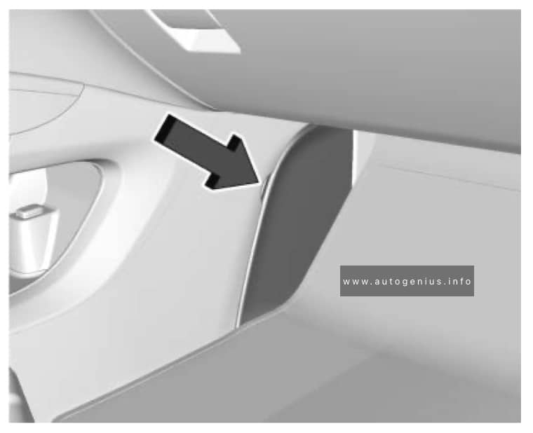
Passenger compartment
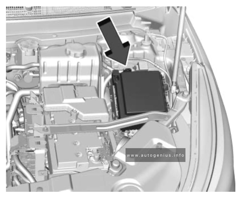
Fuse Box Location
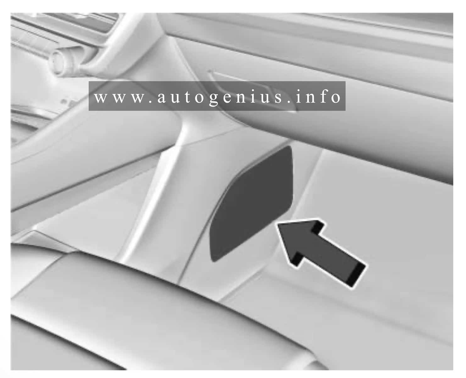
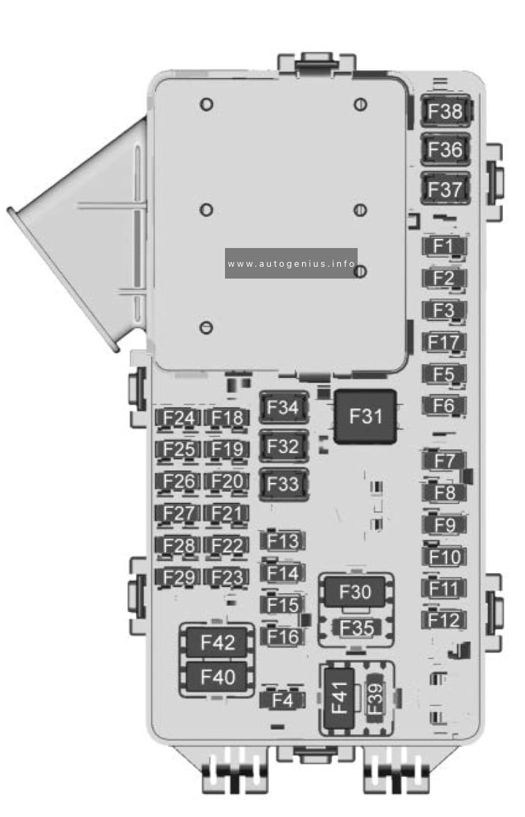
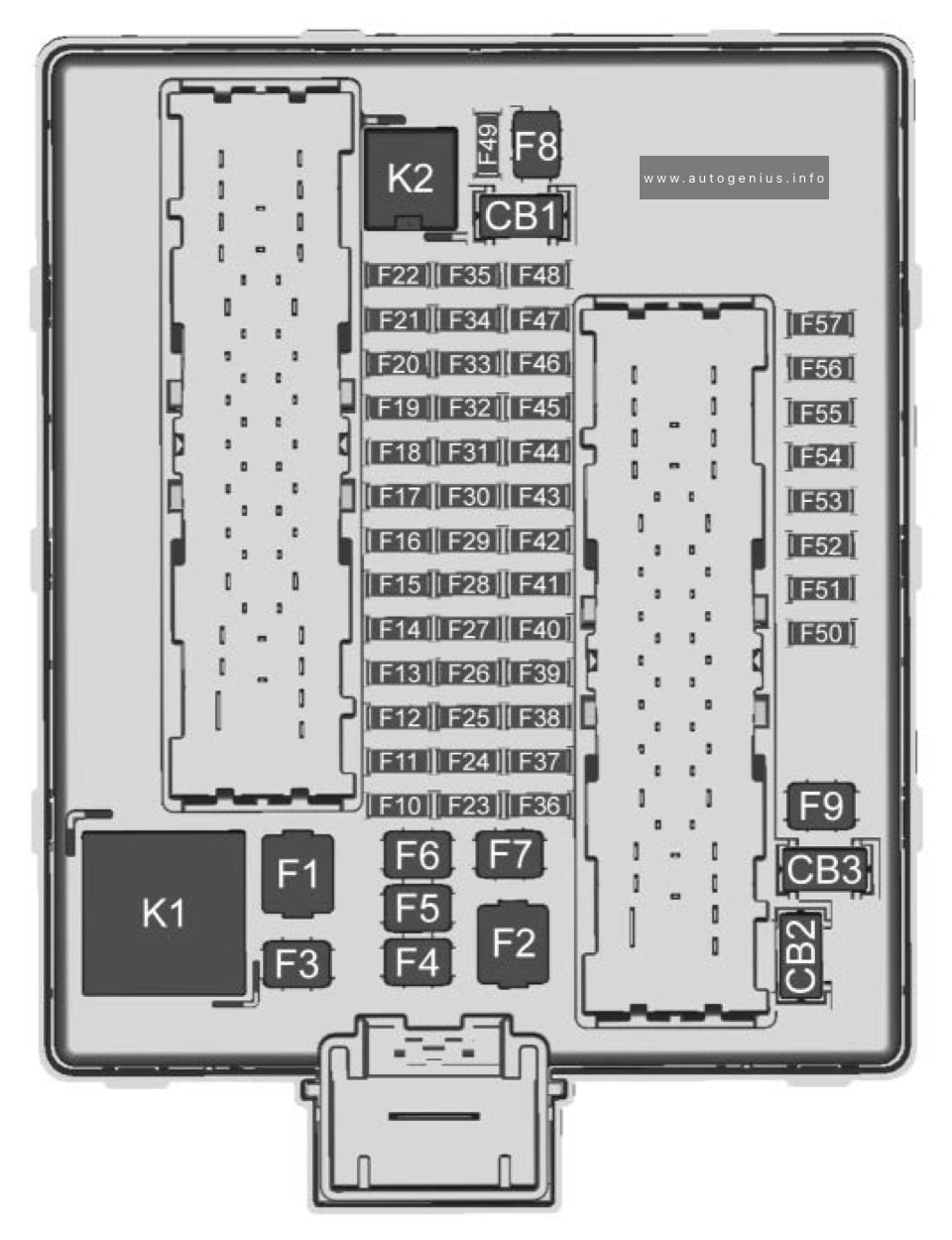
Fuse Box Diagram
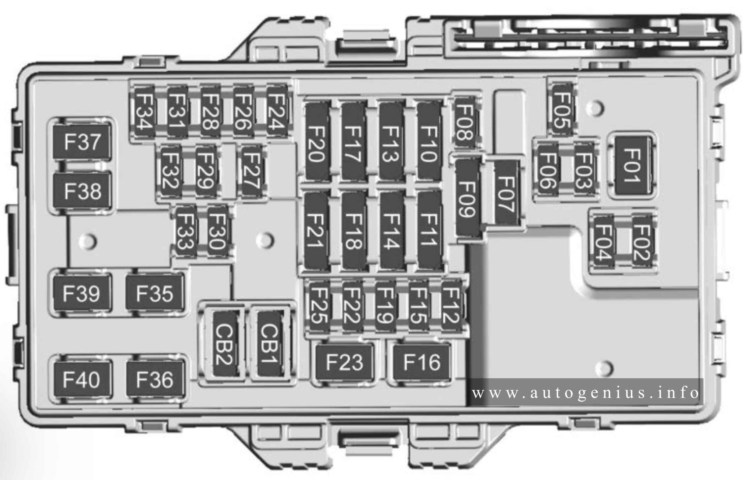
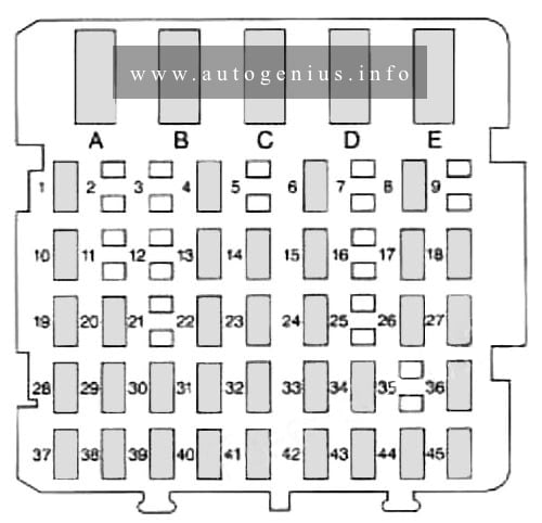
Assignment of the fuses in the passenger compartment
| № | Description |
|---|---|
| F1 | Blower motor |
| F2 | ELM 1 – Exterior Lighting Module 1 |
| F3 | SCL Steering Column Lock |
| F4 | ELM 2 – Exterior Lighting Module 2 |
| F5 | CM 2 – Body Control Module 2 |
| F6 | OHC – OnStar Hands-Free Calling |
| F7 | Steering wheel control |
| F8 | Telematics |
| F9 | BCM BATT 1 & ETS SHIFTER – Body Control Module Battery 1 and Euro Truck Shnifer |
| F10 | UGDO – Universal Garage Door Opener |
| Spare | |
| F11 | HVAC & TPIM – Heating, Ventilation and Air Conditioning and Traction Power Inverter Module |
| F12 | Sterring Column Lock |
| F13 | CGM & DLC – Central Gateway Module and Data Link Connector |
| F14 | EBCM & PCM – Electronic Brake Control Module and Power Control Module |
| F15 | AUX DISPLAY |
| F16 | APO_RR_CARGO – Auxiliary Power Outlet Rear Cargo |
| F17 | SDM_AOS – Sensing Diagnostic Module Automatic Occupant Sensor |
| Spare | |
| F18 | SEAT FAN CTR/ HDLP CO & DR – Seat Fan Control Headlamo CO and Driver |
| F19 | ELM RC – Exterior Lighting Module Ride Control |
| F20 | VKM – Virtual Key Module |
| Spare | |
| F21 | VCU_BATT 1 & 2 – Virtual Cocpit Unit Battery 1 and 2 |
| F22 | SDM – Sensing Data Module |
| F23 | — |
| F43 | WCM – Wireless Charging Module |
| F25 | HVPO – High Voltage Power Outlet |
| F26 | Spare |
| F27 | AUX |
| F28 | LRR – Long Range Radar |
| F29 | SRR – Short Range Radar |
| F30 | — |
| F31 | BCM 3 – Body Control Module 3 |
| F32 | HSWM – Heated Steering Wheel Module |
| F33 | — |
| F34 | CPM – Column Position Module |
| F35 | AMPLIFIER |
| F36 | DC/ DC BATT 2 – Direct Current / Direct Current Battery 2 |
| F37 | BCM 4 – Body Control Module 4 |
| F38 | AMPLIFIER 2 |
| F39 | ELM 6 – Exterior Lighting Module 6 |
| F40 | DCAC – Direct Current Alternating Current |
| F41 | — |
| F42 | Auxiliary power outlet (CB)/ Lighter (Minifuse) |
Engine compartment
Fuse Box Location
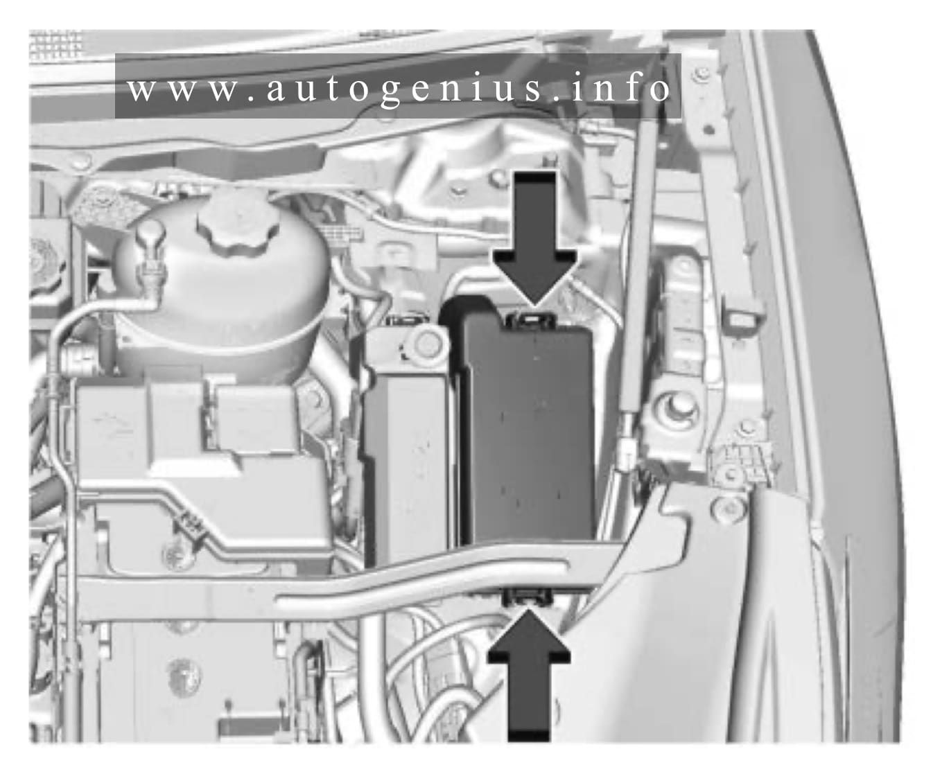
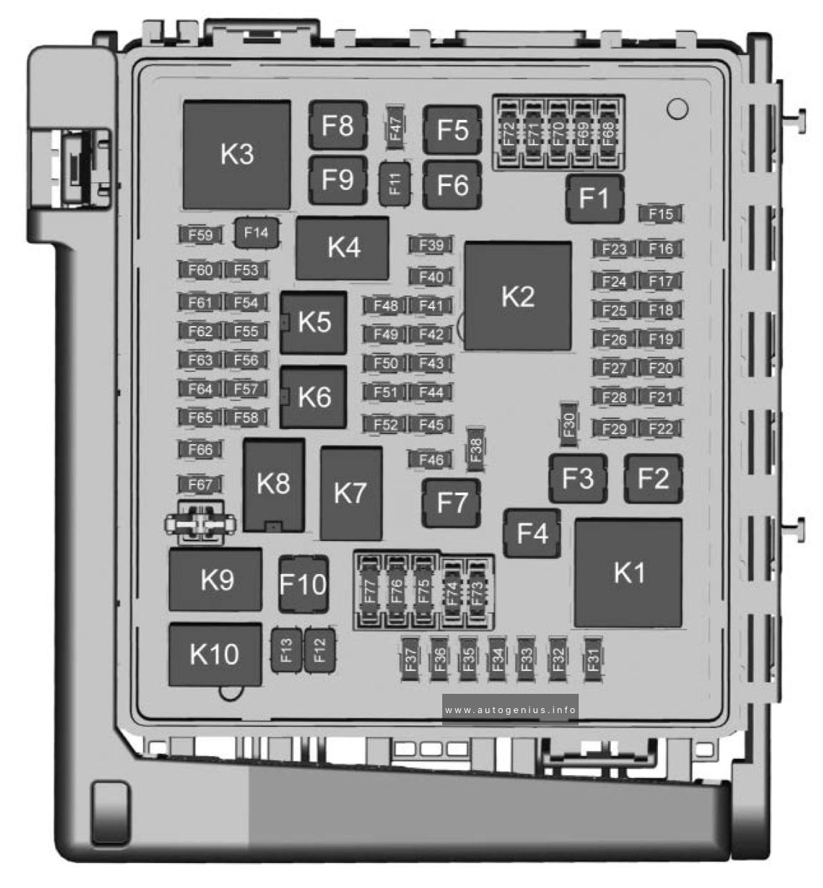
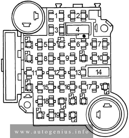
Fuse Box Diagram
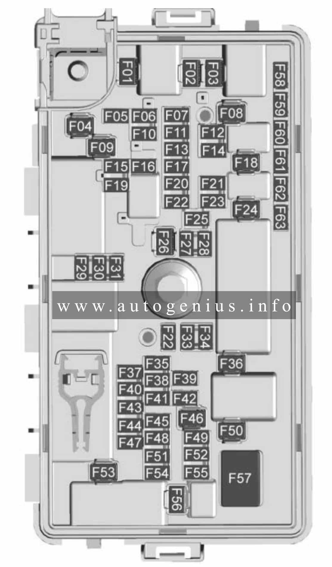
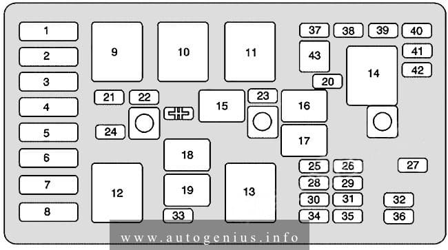
Assignment of the fuses in the engine compartment
| № | Description |
|---|---|
| F1 | Spare |
| F2 | Spare |
| F3 | FRT_WIPER – Front Wiper |
| F4 | Spare |
| F5 | Spare |
| F6 | HDLP RT – Headlamp Right |
| F7 | RR_WIPER – rear Wiper |
| F8 | Spare |
| F9 | RR DEFOG – Rear Defog |
| F10 | ELM 4 – Exterior Lighting Module 4 |
| F11 | HDLP LT – Headlamp Left |
| F12 | HORN |
| F13 | Spare |
| F14 | Spare |
| F15 | Spare |
| F16 | RR_WPR_CTRL – Rear Wiper Control |
| F17 | RLY COIL GND – Relay Coil Ground |
| F18 | DC DC BATT1 – Direct Current Direct Current Battery 1 |
| F19 | ELM7 – Exterior Lighting Module 5 |
| F20 | Spare |
| F21 | Spare |
| F22 | ELM_5 – Exterior Lighing Module 5 |
| F23 | WIPER_DE_ICE |
| F24 | EBCM1 – Electronic Brake Control Module 1 |
| F25 | ELM_3 – Exterior Lighting Module 3 |
| F26 | Spare |
| F27 | TRLR_LTP_TRN_LT – Trailer Lamp Turn Left |
| F28 | TRLR_LTP_TRN_RT – Trailer Lamp Turn Right |
| F29 | WASH |
| F30 | AERO SHUTTER |
| F31 | Spare |
| F32 | PCM – Power Control Module |
| F33 | Spare |
| F34 | Spare |
| F35 | PCM – Power Control Module |
| F36 | STRTR MTR – Starter Motor |
| F37 | AC CLUTCH GAS – Alternating Current Clutch Gas |
| F38 | SOL CP_TURBO BYPASS – Solenoid Turbo Bypass |
| F39 | COIL ODD |
| F40 | Spare |
| F41 | B721_B70_M674 |
| F42 | Spare |
| F43 | Spare |
| F44 | Spare |
| F45 | Spare |
| F46 | Spare |
| F47 | Spare |
| F48 | Spare |
| F49 | Spare |
| F50 | E-PHASER – Electronic Phaser |
| F51 | Spare |
| F52 | PCM – Power Control Module 2 |
| F53 | Spare |
| F54 | AIR_PUMP |
| F55 | Spare |
| F56 | STRTR PINION – Starter Pinion |
| F57 | WATER PUMP |
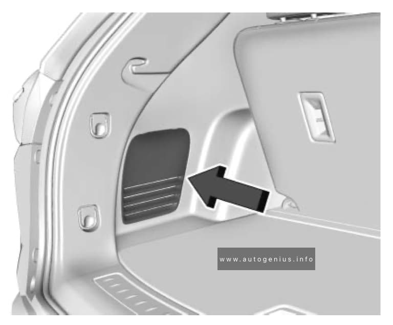
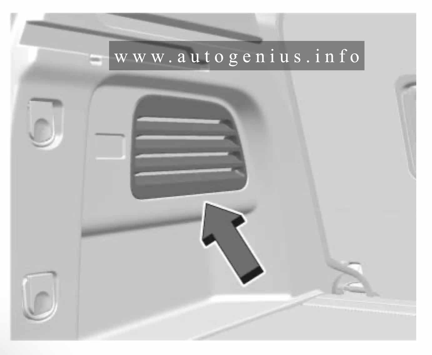
Luggage compartment
Fuse Box Location
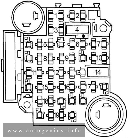
Fuse Box Diagram
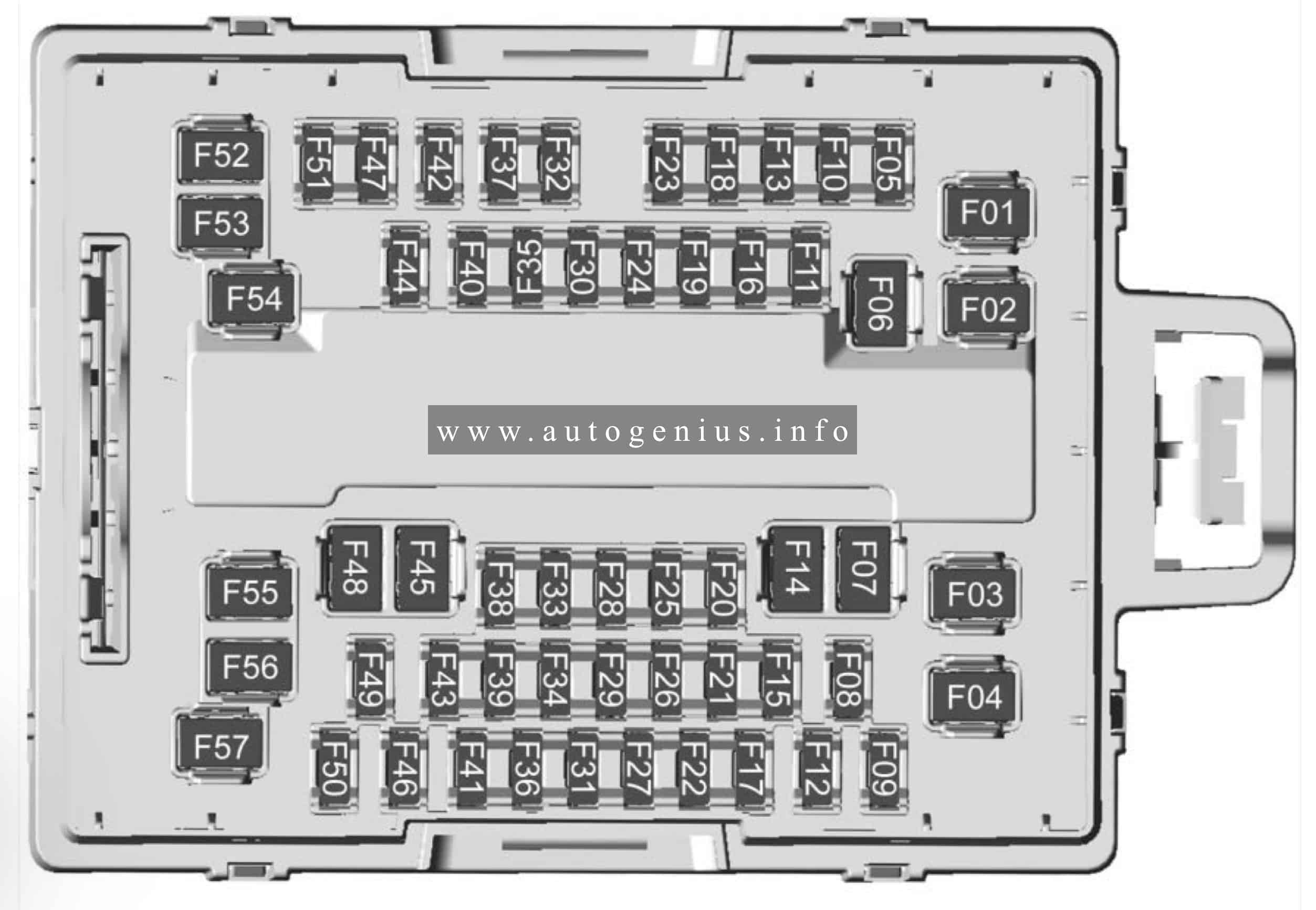
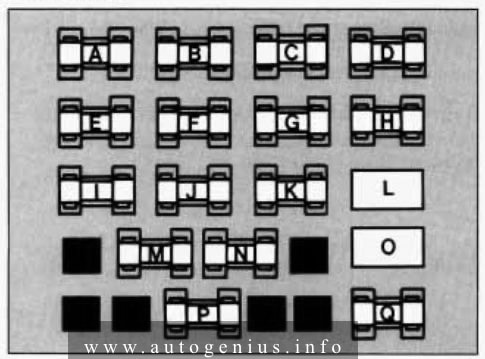
Assignment of the fuses in the luggage compartment
| № | Description |
|---|---|
| F1 | RR_BLOW – Rear Blow |
| F2 | DSP_CODR – Door Switch Panel_Code |
| F3 | TAILGATE |
| F4 | TRLR_BAT1 – Trailer Battery 1 |
| F5 | ACP2 – AWD Control Processor 2 |
| F6 | PWR_FOLD_SEAT_L_R – Power Fold Seat Left and Rear |
| F7 | DSP-DOOR Switch Panel |
| F8 | Spare |
| F9 | LAMPS_RT-Right Lamps |
| F10 | Spare |
| F11 | Spare |
| F12 | ELM 2 – Exterior Lighting Module 2 |
| F13 | LAMPS_LT – Left Lamps |
| F14 | SP_DRVR – Driver |
| F15 | MSM_DRIVER – Memory Seat Module Driver |
| F16 | MTR PFTS_ROW2_L |
| F17 | FRT – Front |
| F18 | SBP_CO_DRIVER |
| F19 | MTR PFTS_ROW2_R |
| F20 | Spare |
| F21 | RFA-Remote Function Actuator |
| F22 | Spare |
| F23 | Spare |
| F24 | Spare |
| F25 | Spare |
| F26 | CANISTER |
| F27 | UPA – Universal Park Assist |
| F28 | RDCM – Right Door Conrol Module |
| F29 | SBZA – Side Blind Zone Assist |
| F30 | TRLR_PRK_LMP – Trailer Park Lamp |
| F31 | FCM – Front Camera Module |
| F32 | Spare |
| F33 | ROW2_BAT1 – Second Row Battery 1 |
| F34 | Spare |
| F35 | Spare |
| F36 | ROW2_BAT2 – Second Row Battery 2 |
| F37 | Spare |
| F38 | Spare |
| F39 | Spare |
| F40 | TRLR_BACK_UP |
| F41 | Spare |
| F42 | DSP-DOOr Switch Panel |
| F43 | POWER FOLD SEAT SW/N 3_ROW |
| F44 | OUT_OF_PARK_DISABLE |
| F45 | TRAILER_BRAKE |
| F46 | ACP3-AWD Control Processor 3 |
| F47 | FTZM – Fuel Tank Zone Module |
| F48 | SP_PASS |
| F49 | Spare |
| F50 | ELM 1 – Exterior Lighting Module 1 |
| F51 | FRT_BAT2 – Front Battery 2 |
| F52 | Spare |
| F53 | Spare |
| F54 | ROW2_FOLD_RH – Second Row Righthand Fold |
| F55 | ROW3 – Thrid Row |
| F56 | SUNROOF |
| F57 | RDCM – Right Door Control Module |
WARNING: Terminal and harness assignments for individual connectors will vary depending on vehicle equipment level, model, and market.