Volkswagen Beetle (Sedan 111, Sedan 113, Converible; 1973) – fuse and relay box diagram
Year of production: 1973
The classic compact car Volkswagen Beetle was produced from 1938 to 2003. In this article, you will find fuse box diagrams for the Volkswagen Beetle models from – 1973, get information about the location of the fuse panels inside the vehicle, and learn about the assignment of each fuse (fuse layout) and relay.
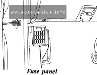
Passenger compartment
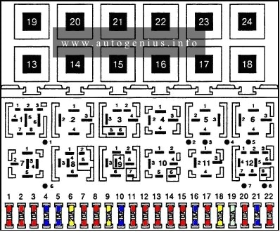
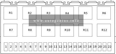
Fuse box diagram
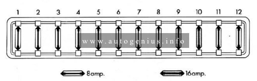
Assignment of the fuses in the passenger compartment
| Fuse | Ampere rating | Description |
| 1 | 8 | Parking and side marker lights, left, tail lights left |
| 2 | 8 | Parking and side marker lights, right, tail right left |
| 3 | 8 | Low beam left |
| 4 | 8 | Low beam right |
| 5 | 8 | High beam left |
| 6 | 8 | High beam right, high beam indicator light |
| 7 | 8 | License flasher system |
| 8 | 8 | Emergency flasher system |
| 9 | 16 | Interior light |
| 10 | 16 | Windshield wipers, rear windows defrogger (switch current), fresh air fan |
| 11 | 8 | Horn, stop lights, control valve* and AFT warning lights** (Automatic Stick Shift) |
| 12 | 8 | Fuel gauge, turn signals, brake warning light, warning lights for oil pressure, turning signals and generator |
* if this fuse is detective, the transmission cannot be shifted
** trailer hauling only
WARNING: Terminal and harness assignments for individual connectors will vary depending on vehicle equipment level, model, and market.