J160 – Circulation pump relay2)
J708 – Residual heat relay2)
R149 – Remote control receiver for auxiliary coolant heater2)
U18 – 12 V socket 21)
U20 – 12 V socket 41)
3
15
202)
U5 – 12 V socket
U19 – 12 V socket 3
4
20
J162 – Heater control unit
5
20
U18 – 12 V socket 22)
U19 – 12 V socket 42)
J807 – Relay for power sockets1)
6
15
J518 – Entry and start authorisation control unit3)
J708 – Residual heat relay1)
7
5
T16b – Diagnostic connection
J515 – Aerial selection control unit
G397 – Rain and light detector sensor
8
25
307)
V – Windscreen wiper motor
9
15
J519 – Onboard supply control unit (windscreen wiper pump)
10
25
307)
J388 – Rear left door control unit (window regulator)
11
15
J386 – Driver door control unit (central locking)
J388 – Rear left door control unit (central locking)
12
10
J519 – Onboard supply control unit (interior light)
13
–
Not assigned
14
25
307)
J386 – Driver door control unit (window regulator)
15
15
J393 – Convenience system central control unit (right tail light cluster)
16
20
J519 – Onboard supply control unit (fanfare)
17
30
J519 – Onboard supply control unit (left light)
18
20
257)
J39 – Headlight washer system relay
19
–
Not assigned
20
30
J519 – Onboard supply control unit (battery 1)
21
–
Not assigned
22
30
J647 – Axle differential lock control unit
J605 – Rear lid control unit
23
10
J647 – Axle differential lock control unit
24
5
J502 – Tyre pressure monitor control unit
25
15
J352 – Steering column and belt height adjustment control unit
26
10
F36 – Clutch pedal switch
J… – Engine control units
J234 – Airbag control unit
J285 – Control unit in dash panel insert
J519 – Onboard supply control unit
K145 – Front passenger side airbag deactivated warning lamp
N378 – Driver seat belt inertia reel magnet
N379 – Front passenger side seat inertia reel magnet
27
5
E183 – Interior monitoring switch
W11 – Rear left reading light
W12 – Rear right reading light
W14 – Front passenger side illuminated vanity mirror
W20 – Driver side illuminated vanity mirror
W51 – Rear lid light
28
–
Not assigned
29
–
Not assigned
30
–
Not assigned
31
–
Not assigned
32
–
Not assigned
33
15
J527 – Steering column electronics control unit
34
5
G273 – Interior monitoring sensor
G384 – Vehicle inclination sender
J285 – Control unit in dash panel insert2)
35
30
J519 – Onboard supply control unit
36
30
E470 – Driver seat adjustment operating unit
37
–
Not assigned
38
–
Not assigned
39
5A
J9 – Heated rear window relay
J32 – Air conditioning system relay
J329 – Terminal 15 voltage supply relay
J755 – Transport mode relay
J807 – Relay for power sockets1)
40
5
J285 – Control unit in dash panel insert
41
15
J518 – Entry and start authorisation control unit
42
30
J245 – Sliding sunroof adjustment control unit
43
–
Not assigned
44
30
E470 – Driver seat adjustment operating unit
J136 – Seat and steering column adjustment control unit with memory
J810 – Driver seat adjustment control unit
45
25
J786 – Heated rear seats control unit
46
–
Not assigned
47
10
J647 – Axle differential lock control unit
48
5
J769 – Lane change assist control unit
J770 – Lane change assist control unit 2
49
5
J236 – Servotronic control unit
50
10
G266 – Oil level and oil temperature sender
N79 – Crankcase breather heater element4)
51
5
T16b – Diagnostic connection
F321 – Parking brake contact switch
G238 – Air quality sensor
G550 – Sensor for automatic distance control
J755 – Transport mode relay
52
30
157)
V12 – Rear window wiper motor
53
5
E1 – Light switch
J527 – Steering column electronics control unit
J393 – Convenience system central control unit
54
10
E102 – Headlight range control regulator5)
J667 – Power output module for left headlight6)
V48 – Left headlight range control motor5)
V49 – Right headlight range control motor5)
55
15
J486 – Fresh air blower relay for 2nd speed
56
40
J32 – Air conditioning system relay
J309 – Solar cell isolation relay
J486 – Fresh air blower relay, 2nd speed
SB55 – Fuse 55 on fuse holder B
V305 – Motor for front Bitron blower regulation
57
40
V306 – Motor for rear Bitron blower regulation8)
J403 – Adaptive suspension compressor relay7)
1) Only one battery onboard supply
2) Only auxiliary battery and two battery onboard supply
3) Only V10 TDI
4) Only models with engine codes BHK, BHL
5) Only models with halogen headlights
6) Only models with cornering light
7) From November 2007
8) Up to November 2007
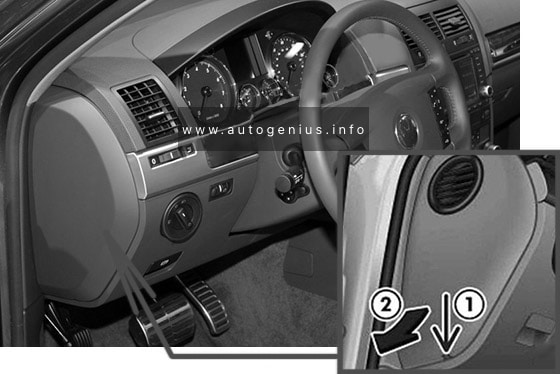
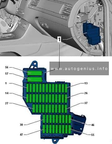
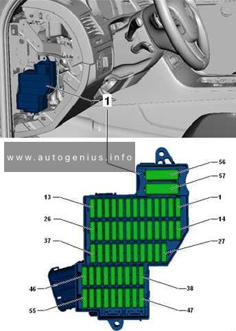
Fuse assignment in fuse box, right-side dash panel
Assignment of the fuses in the right-side of the dash panel.
No.
А
Function/component
1
15
202)
J345 – Trailer detector control unit
2
5
J446 – Parking aid control unit
3
15
J345 – Trailer detector control unit
4
5
J412 – Mobile telephone operating electronics control unit
5
15
252)
J345 – Trailer detector control unit
6
30
J104 – ABS control unit
7
5
J646 – Transfer box control unit
8
30
J519 – Onboard supply control unit (right light)
9
10
Individualisation
R190 – Satellite digital radio tuner1)
10
5
J772 – Reversing camera system control unit
R78 – TV tuner
11
20
J503 – Control unit with display for radio and navigation system
R – Radio
R – Preparation for radio and navigation system with TV (models for Japan)
12
30
R12 – Amplifier
13
–
Not assigned
14
15
J393 – Convenience system central control unit
15
25
303)
J389 – Rear right door control unit (window regulator)
16
10
53)
W3 – Luggage compartment light
17
–
Not assigned
18
30
J9 – Heated rear window relay
19
–
Not assigned
20
30
U13 – AC/DC converter with socket 12 V – 230 V
U27 – AC/DC converter with socket 12 V – 115 V1)
21
10
F266 – Bonnet contact switch
22
25
J774 – Heated front seats control unit
23
10
J255 – Climatronic control unit
24
30
E471 – Front passenger seat adjustment operating unit
J521 – Front passenger seat adjustment with memory control unit
25
5
E265 – Rear Climatronic operating and display unit
J301 – Air conditioning system control unit
26
–
Not assigned
27
15
J197 – Adaptive suspension control unit
28
–
Not assigned
29
10
53)
J217 – Automatic gearbox control unit
30
20
J714 – Power latching system relay
31
15
J393 – Convenience system central control unit
32
10
J387 – Front passenger door control unit (central locking)
J389 – Rear right door control unit (central locking)
33
15
Individualisation
34
25
303)
J387 – Front passenger side door control unit (window regulator)
35
30
E471 – Front passenger seat adjustment operating unit
36
5
J603 – Vehicle position recognition control unit
J702 – Roof display unit
37
–
Not assigned
38
10
J104 – ABS control unit
39
5
J410 – Heated windscreen relay for left side
J411 – Heated windscreen relay for right side
J745 – Cornering light and headlight range control unit
Individualisation
40
10
J646 – Transfer box control unit
41
10
J345 – Trailer detector control unit
42
5
E284 – Garage door operating unit
J530 – Garage door operation control unit
43
5
F41 – Reversing switch
44
5
E94 – Heated driver seat regulator
E95 – Heated front passenger seat regulator
E128 – Heated rear left seat switch with regulator
E129 – Heated rear right seat switch with regulator
E281 – Operating unit to regulate suspension height
Z20 – Left washer jet heater element
Z21 – Right washer jet heater element
45
–
Not assigned
46
–
Not assigned
47
10
J668 – Power output module for right headlight
48
10
J197 – Adaptive suspension control unit
49
5
Y7 – Automatic anti-dazzle interior mirror
50
5
E256 – TCS and ESP button
51
15
J217 – Automatic gearbox control unit
52
5
F125 – Multifunction switch
F189 – Tiptronic switch
N380 – Selector lever lock for position P solenoid
53
30
J411 – Heated windscreen relay for right side
54
30
J410 – Heated windscreen relay for left side
55
–
Not assigned
56
40
J104 – ABS control unit
57
40
J646 – Transfer box control unit
1) Only American markets
2) From May 2008
3) From November 2007
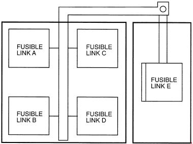
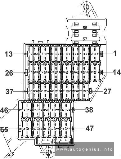
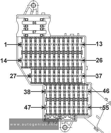
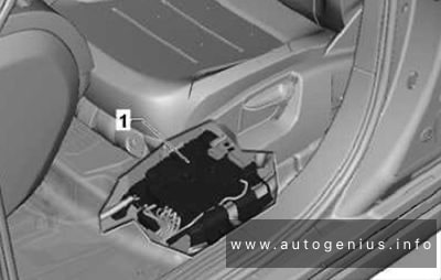
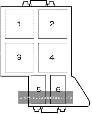
Fuses and relay position assignment in pre-fuse box, under driver seat
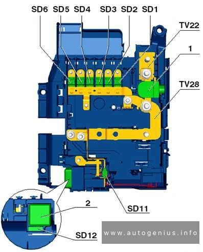
Fuse box diagram
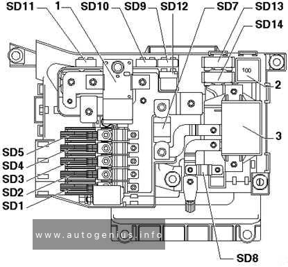
Volkswagen Touareg – fuse and relay box diagram – passenger compartment (pre-fuse, under driver seat)
Pre-fuse box (under driver seat).
No.
А
Function/component
SD1
150
Left fuse carrier
SD2
150
Right fuse carrier
SD3
60
Right fuse carrier
SD4
60
403)
J701 – Voltage supply relay 21)
V306 – Motor for rear Bitron blower regulation3)
SD5
60
403)
J329 – Terminal 15 voltage supply relay
SD6
–
Not assigned
SD7
250
J713 – Charger relay for second battery
SD8
1501)
602)
Left fuse carrier
J701 – Voltage supply relay 11)
SD9
5
J519 – Onboard supply control unit
SD10
10
53)
J519 – Onboard supply control unit1)
SD11
5
J519 – Onboard supply control unit1)
SD12
–
Not assigned
SD13
40
J403 – Adaptive suspension compressor relay
V306 – Motor for rear Bitron blower regulation1,3)
SD14
–
Not assigned
Relays
1
Battery master/isolator switch -E74-
2
Terminal 15 voltage supply relay -J329- (433)
3
Second battery charging circuit relay -J713-
1) Only V10 TDI
2) Only models with additional battery
3) From November 2007
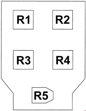
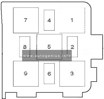
Relay locations for E-box on left under dash panel near centre console
Fuse box diagram
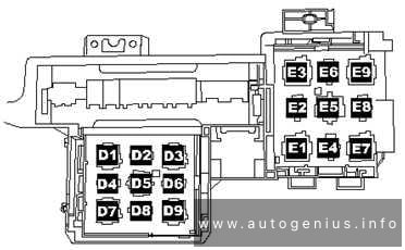
Volkswagen Touareg – fuse and relay box diagram – passenger compartment (e-box; left-side under dashpanel)
Relay panel E-Box 1 (on left under dash panel near center console).
No.
Function/component
D1
Servotronic control unit -J236- (476)
D2
Power latching system relay -J714- (404)
D3
Adaptive suspension compressor relay -J403- (373)
D4
Power sockets relay -J807- (404)
D5
Air conditioning system relay -J32- (100) / (370) optional installation
D6
Fresh air blower relay, 2nd speed -J486- (404), only manually operated air conditioning system
D7
Heated rear window relay -J9- (53)
D8
Circulation pump relay -J160- (404), only VR6 with auxiliary heater
D9
Alternator cut-in relay -J442- (53)
E1
Solar cells isolation relay -J309- (79)
E2
Not assigned
E3
Heated windscreen relay for left side -J410- (53)
E4
Not assigned
E5
Voltage supply relay 2 -J710- (432), only V10 TDI
E6
Not assigned
E7
Headlight washer system relay -J39- (53)
E8
Residual heat relay -J708- (404)
E9
Heated windscreen relay for right side -J411- (53)
Relay carrier on E-box on right under dash panel, near right a-pillar (only right-hand drive)
Fuse box diagram
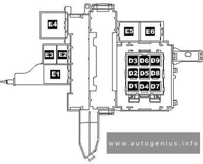
Volkswagen Tourareg – fuse and relay box diagram – relay carrier on E-box on right-side under dash panel, near right a-pillar (only right-hand drive)
Relay panel E-box 2 (on right under dash panel, near right a-pillar)
No.
Function/component
D1
Servotronic control unit -J236- (476)
D2
Power latching system relay -J714- (404)
D3
Adaptive suspension compressor relay -J403- (373)
D4
Power sockets relay -J807- (404)
D5
Air conditioning system relay -J32- (100) / (370) optional installation
D6
Fresh air blower relay, 2nd speed -J486- (404), only manually operated air conditioning system
D7
Heated rear window relay -J9- (53)
D8
Circulation pump relay -J160- (404), only VR6 with auxiliary heater
D9
Alternator cut-in relay -J442- (53)
E1
Solar cells isolation relay -J309- (79)
E2
Residual heat relay -J708- (404)
E3
Heated windscreen relay for left side -J410- (53)
E4
Voltage supply relay 2 -J710- (432), only V10 TDI
E5
Heated windscreen relay for right side -J411- (53)
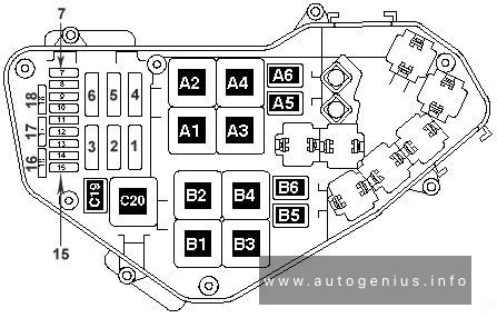
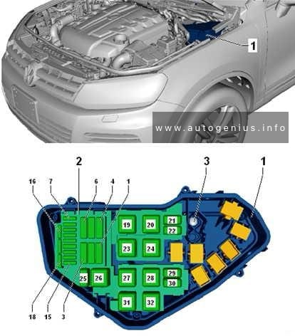
Volkswagen Touareg – fuse and relay box diagram – engine compartment relay & fuse box (2.5 l (R5) TDI engine)
Assignment of the fuses in the Engine compartment (2.5L (R5) TDI engine)
No.
A
Function/component
1
60
J293 – Radiator fan control unit
2
30
J671 – Radiator fan control unit 21)
3
–
Not assigned
4
–
Not assigned
5
–
Not assigned
6
–
Not assigned
7
–
Not assigned
8
–
Not assigned
9
30
J623 – Engine control unit
10
10
G65 – High-pressure sender
J17 – Fuel pump relay
J255 – Climatronic control unit
J293 – Radiator fan control unit
J301 – Air conditioning system control unit
J445 – Fuel cooling pump relay
J496 – Additional coolant pump relay
J671 – Radiator fan control unit 2
N75 – Charge pressure control solenoid valve
N79 – Crankcase breather heater element
N280 – Air conditioner compressor regulating valve
N345 – Exhaust gas recirculation cooler changeover valve
11
–
Not assigned
12
10
J179 – Automatic glow period control unit
J496 – Additional coolant pump relay
J248 – Diesel direct injection system control unit
J623 – Engine control unit
10
10
G65 – High-pressure sender
J17 – Fuel pump relay
J179 – Automatic glow period control unit
J255 – Climatronic control unit
J293 – Radiator fan control unit
J301 – Air conditioning system control unit
J338 – Throttle valve module3)
J442 – Alternator cut-in relay2)
J445 – Fuel cooling pump relay
J496 – Additional coolant pump relay
J671 – Radiator fan control unit 2
J724 – Turbocharger 1 control unit
J865 – Control unit for charge air cooler bypass3)
N18 – Exhaust gas recirculation valve
N280 – Air conditioner compressor regulating valve
N345 – Exhaust gas recirculation cooler changeover valve
N381 – Exhaust gas recirculation cooler changeover valve 23)
N428 – Valve block 2 in front passenger side rear seat3)
V157 – Intake manifold flap motor
V275 – Intake manifold flap 2 motor
V400 – Pump for exhaust gas recirculation cooler3)
G65 – High-pressure sender
J17 – Fuel pump relay
J293 – Radiator fan control unit
J671 – Radiator fan control unit 2
N345 – Exhaust gas recirculation cooler changeover valve
N381 – Exhaust gas recirculation cooler changeover valve 2
V336 – Metering pump for post-injection in particulate filter for cylinder bank 12)
V337 – Metering pump for post-injection in particulate filter for cylinder bank 22)
11
15
F265 – Map-controlled engine cooling system thermostat
J255 – Climatronic control unit
J724 – Turbocharger 1 control unit
J725 – Turbocharger 2 control unit
N280 – Air conditioner compressor regulating valve
V135 – Particulate filter additive pump2)
V157 – Intake manifold flap motor
V275 – Intake manifold flap 2 motor
V280 – Turbocharger 1 control motor
V281 – Turbocharger 2 control motor
12
5
J179 – Automatic glow period control unit
J445 – Fuel cooling pump relay
J496 – Additional coolant pump relay
J703 – Glow period control unit 2
Volkswagen Touarge – fuse and relay box diagram – engine compartment relay & fuse box (3.6 l (V6) FSI engine)
Assignment of the fuses in the Engine compartment (3.6L (V6) FSI engine)
No.
A
Function/component
1
60
J293 – Radiator fan control unit
2
301)
J671 – Radiator fan control unit 2
V7 – Radiator fan
3
–
Not assigned
4
–
Not assigned
5
–
Not assigned
6
–
Not assigned
7
20
N70 – Ignition coil 1 with output stage
N127 – Ignition coil 2 with output stage
N291 – Ignition coil 3 with output stage
8
20
N292 – Ignition coil 4 with output stage
N323 – Ignition coil 5 with output stage
N324 – Ignition coil 6 with output stage
9
30
J623 – Engine control unit
10
10
G65 – High-pressure sender
J293 – Radiator fan control unit
J496 – Additional coolant pump relay
J671 – Radiator fan control unit 21)
V144 – Fuel system diagnostic pump
11
10
J255 – Climatronic control unit
J301 – Air conditioning system control unit
J442 – Alternator cut-in relay2)
N280 – Air conditioner compressor regulating valve
12
10
N80 – Activated charcoal filter system solenoid valve 1
N205 – Inlet camshaft control valve 1
N316 – Intake manifold flap valve
N318 – Exhaust camshaft control valve 1
13
25
J538 – Fuel pump control unit
14
15
N276 – Fuel pressure regulating valve
15
10
J623 – Engine control unit
J271 – Motronic current supply relay
J670 – Motronic current supply relay 2
Volkswagen Touareg – fuse and relay box diagram – Engine compartment relay & fuse box (4.2 l (V8) FSI engine)
Assignment of the fuses in the Engine compartment (4.2L (V8) FSI engine)
No.
A
Function/component
1
60
J671 – Radiator fan control unit 2
V177 – Radiator fan 2
2
601)
30
J293 – Radiator fan control unit
V7 – Radiator fan
3
40
J299 – Secondary air pump relay
V101 – Secondary air pump motor
4
–
Not assigned
5
–
Not assigned
6
–
Not assigned
7
20
N70 – Ignition coil 1 with output stage
N127 – Ignition coil 2 with output stage
N291 – Ignition coil 3 with output stage
N292 – Ignition coil 4 with output stage
N323 – Ignition coil 5 with output stage
N324 – Ignition coil 6 with output stage
N325 – Ignition coil 7 with output stage
N326 – Ignition coil 8 with output stage
8
–
Not assigned
9
30
J623 – Engine control unit
10
10
G70 – Air mass meter
G246 – Air mass meter 2
J299 – Secondary air pump relay
N80 – Activated charcoal filter solenoid valve 1
V144 – Fuel system diagnostic pump
11
–
Not assigned
12
20
F265 – Map-controlled engine cooling system thermostat
G65 – High-pressure sender
J151 – Continued coolant circulation relay
J255 – Climatronic control unit
J301 – Air conditioning system control unit
J293 – Radiator fan control unit
J442 – Alternator cut-in relay2)
J671 – Radiator fan control unit 2
N205 – Inlet camshaft control valve 1
N208 – Inlet camshaft control valve 2
N280 – Air conditioner compressor regulating valve
N318 – Exhaust camshaft control valve 1
N319 – Exhaust camshaft control valve 2
V157 – Intake manifold flap motor
V183 – Variable intake manifold motor
J623 – Engine control unit
J624 – Engine control unit 2
10
10
G65 – High-pressure sender
J255 – Climatronic control unit
J293 – Radiator fan control unit
J301 – Air conditioning system control unit
J442 – Alternator cut-in relay2)
J671 – Radiator fan control unit 2
V144 – Fuel system diagnostic pump
11
15
N80 – Activated charcoal filter solenoid valve 1
N205 – Inlet camshaft control valve 1
N208 – Inlet camshaft control valve 2
N280 – Air conditioner compressor regulating valve
N318 – Exhaust camshaft control valve 1
N319 – Exhaust camshaft control valve 2
12
5
J49 – Electric fuel pump 2 relay
J299 – Secondary air pump relay
J545 – Secondary air pump relay 2
J624 – Engine control unit 2
Year of production: 2010, 2011, 2012, 2013, 2014, 2015, 2016, 2017, 2018
This article provides the second-generation Volkswagen Touareg (7P), manufactured between 2010 and 2018. It provides fuse box diagrams for the Volkswagen Touareg models from 2011 to 2018, along with details on the location of the fuse panels within the vehicle. Additionally, you’ll find information on the fuse layout and the functions of each fuse and relay.
Fuse assignment in fuse box, right-side instrument panel
Assignment of the fuses in the right-side of the instrument panel
No.
А
Function/component
1
–
Not assigned
2
15
Adaptive suspension control unit -J197-
3
10
Axle differential lock control unit -J647-
4
30
Axle differential lock control unit -J647-
5
25
156
Trailer detector control unit -J345-
6
15
Trailer detector control unit -J345-
7
15
256
Trailer detector control unit -J345-
8
15
256
Trailer detector control unit -J345-
9
30
Rear right door control unit -J389-
10
–
Not assigned
11
30
Front passenger door control unit -J387-
12
–
Not assigned
13
15
Trailer detector control unit -J345-6
14
10
Airbag control unit -J234-
Front passenger airbag deactivated warning lamp -K145-
Seat occupied recognition control unit -J706-3
15
10
Transfer box control unit -J646-
16
5
Control unit for electromechanical parking brake -J540-
Operating unit to regulate suspension height -E281-
Left washer jet heater element -Z20-
Right washer jet heater element -Z21-
Button for TCS and electronic stabilisation program -E256-
ABS control unit -J104-
Hill descent control button -E618-
Electromechanical parking brake button -E538-
Auto-hold button -E540-6
Voltage stabiliser -J532-2
17
15
Front right headlight -MX2-
18
30
Igniter for front passenger side seat belt tensioner 2 -N298-
19
5
Tiptronic switch -F189-
Multifunction switch -F125-
Automatic gearbox control unit -J217-
20
25
Front passenger seat position control unit -J720-1
Valve block 1 in front passenger seat -N477-1
Control unit for front passenger multicontour seat -J872-1
Control unit for front right seat ventilation -J799-1
Front passenger seat rake adjustment button -E334-1
Front passenger seat longitudinal adjustment switch -E64-1
Front passenger side height adjustment switch -E290-1
Front passenger seat backrest adjustment switch -E98-1
Front passenger seat lumbar support adjustment switch -E177-1
21
25
Heated rear seats control unit -J786-1
Operating and display unit for rear air conditioning system -E265-1
22
–
Not assigned
23
25
Rear lid control unit -J605-
24
10
Climatronic control unit -J255-
Operating and display unit for rear air conditioning system -E265-1
25
5
Control unit for overhead view camera -J928-
Reversing camera system control unit -J772-
26
30
Heated rear window relay -J9-
27
5
Remote control receiver for auxiliary coolant heater -R149-
28
20
Gearbox hydraulic pump relay -J510-
Transfer box control unit -J646-
Automatic gearbox control unit -J217-
28
55
206
Transfer box control unit -J646-
29
30
ABS control unit -J104-
30
5
Tiptronic switch -F189-5
31
306,7
205
Convenience system central control unit -J393-
32
30
Rear fresh air blower -V80-4
33
30
Convenience system central control unit -J393-
34
–
Not assigned
35
5
Control unit for vehicle location system -J895-4
36
30
Convenience system central control unit -J393-
37
20
Automatic gearbox control unit -J217-5
Gearbox hydraulic pump relay -J510-5
38
15
Cigarette lighter -U1-
12 V socket 2 -U18-
Heated rear seats control unit -J786-
39
15
12 V socket 3 -U19-
12 V socket 4 -U20-
40
20
304
DC/AC converter with socket, 12 V – 230 V -U13-
41
10
Connection 2 for external audio sources -R231-5 Not assigned6
42
5
Trailer detector control unit -J345-
43
10
Axle differential lock control unit -J647-
44
5
Air quality sensor -G238-
45
30
Voltage stabiliser -J532-2
46
30
Voltage stabiliser -J532-2
47
10
Control unit 1 for information electronics -J794-
Display unit for front information display and operating unit control unit -J685-
48
30
Digital sound package control unit -J525-1
49
–
Not assigned
50
5
TV tuner -R78-1
Mobile telephone operating electronics control unit -J412-1
51
20
Radio -R-
52
5
Control unit in dash panel insert -J285-
53
5
DVD changer -R161-
54
5
Interface for external multimedia unit -R215-4
55
–
Not assigned
56
40
ABS control unit -J104-
57
40
Control unit for electromechanical parking brake -J540-
Transfer box control unit -J646-
1) According to equipment
2) Only models with start/stop system
3) Only for American markets
4) From November 2010
5) From November 2012
6) From August 2014
7) Up to November 2012
Fuse assignment in fuse box, left-side instrument panel
Radiator fan control unit -J293-
Automatic glow period control unit -J179-
Additional coolant pump relay -J496-
Brake light switch -F-
Exhaust gas recirculation cooler changeover valve -N345-
Exhaust gas recirculation cooling bypass valve -N386-
Valve for oil pressure control -N428-
Throttle valve module -J338-
Radiator fan control unit -J293-
Automatic glow period control unit -J179-
Additional coolant pump relay -J496-
Brake light switch -F-
Exhaust gas recirculation cooler changeover valve -N345-
Coolant valve for cylinder head -N489-
Valve for oil pressure control -N428-
Map-controlled engine cooling system thermostat -F265-
Right electrohydraulic engine mounting solenoid valve -N145-1
Radiator fan control unit -J293-
Automatic glow period control unit -J179-
Glow period control unit 2 -J703-
Additional coolant pump relay -J496-
Brake light switch -F-
Exhaust gas recirculation cooler changeover valve -N345-
Coolant valve for cylinder head -N489-
Valve for oil pressure control -N428-
Throttle valve module -J338-
11
15
Oil level and oil temperature sender -G266-
Heater element for crankcase breather -N79-
Heater element 2 for crankcase breather -N483-
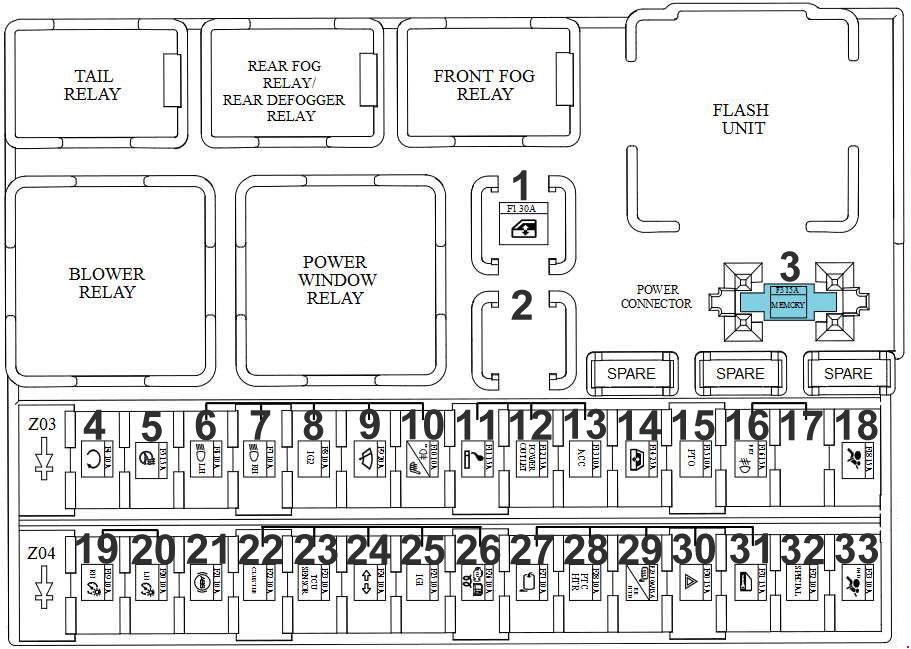
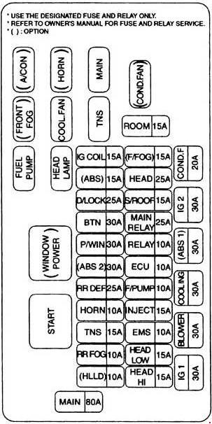
Room Lamp, Door Warning Switch, Audio. ETACM, Instrument Cluster, Data Link Connector.Room Lamp (Double Cab)
4
10
Glow Control Module (D4BB). E/R Junction Box (RLY. 4)
5
15
–
6
10
Head Lamp LH, Instrument Cluster
7
10
Head Lamp RH
8
10
Heater Control Switch, ETACM. Head Lamp Leveling Switch. Blower Relay, Front Fog Lamp Relay, E/R Junction Box (RLY. 5), Head Lamp Leveling Actuator LH/RH
9
20
Wiper Motor, Multifunction Switch (INT)
10
10
Rear Foq Lamp Relay
11
15
Cigarette Lighter
12
15
–
13
10
Audio, ETACM
14
25
–
15
10
–
16
15
Front Fog Lamp Relay
18
15
Instrument Cluster. Driver Power Window Switch. Rear Defogger Switch, Head Lamp Leveling Switch, Heated Control Switch
18
10
Position Lamp RH, Rear Combination Lamp RH, License Lamp (Standard), Hazard Switch, Audio, Rear Detogger Switch, Heater Control Switch, Instrument Cluster, Head Lamp Leveling Switch, Driver Power Window Switch
20
10
Position Lamp LH, Rear Combination Lamp LH, License Lamp (Dual)
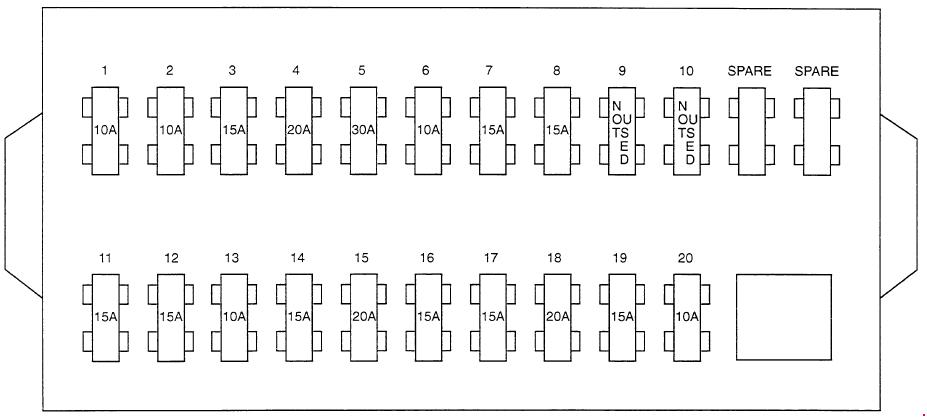
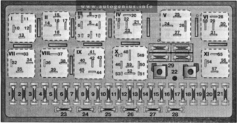
Audi 90 (B3; 1987 – 1991) – fuse and relay box diagram
Year of production: 1987, 1988, 1989, 1990, 1991
This article covers the Audi 90 (B3), produced from 1987 to 1991. It includes fuse box diagrams for the 1987, 1988, 1989, 1990 and 1991 models, provides details on the location of the fuse panels inside the vehicle, and explains the function and layout of each fuse.
Fuse box diagram
Audi 90 (B3; 1987 – 1991) – fuse and relay box diagram
Assignment of the fuses in the fuse box
No.
Description
A
1
Fog lights, rear fog light
15
2
Emergency flashers
15
3
Horn, brake lights
25
4
Reading lights, luggage compartment, cigar lighter, interior lights, make-up mirror, Board Computer, radio, clock, auto climate control, alarm system
15
5
Radiator cooling fan
30
6
Side marker, park lights, right
5
7
Side marker, park lights, left
5
8
Hi-beam headlight, right, hi-beam indicator light
10
9
Hi-beam headlight, left
10
10
Low beam headlight, right
10
11
Low beam headlight, left
10
12
Instrument cluster, back-up lights, Auto-Check, cruise control, ABS, Board Computer, differential locks, electronic thermoswitch, throttle valve time control unit, radiator cooling fan after-run control unit
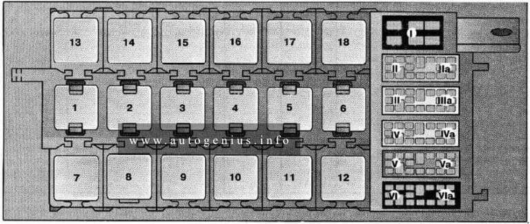
Audi 80 (B3; 1986 – 1991) – fuse and relay box diagram
Year of production: 1986, 1987, 1988, 1989, 1990, 1991
This article covers the Audi 80 (B3), produced from 1986 to 1991. It includes fuse box diagrams for the 1986, 1987, 1988, 1989, 1990 and 1991 models, provides details on the location of the fuse panels inside the vehicle, and explains the function and layout of each fuse.
Fuse Box diagram
Audi 80 (B3; 1986 – 1991) – fuse and relay box diagram
Assignment of the fuses in the fuse box
No.
Description
A
1
Fog lights, rear fog light
15
2
Emergency flashers
15
3
Horn, brake lights
25
4
Reading lights, luggage compartment, cigar lighter, interior lights, make-up mirror, Board Computer, radio, clock, auto climate control, alarm system
15
5
Radiator cooling fan
30
6
Side marker, park lights, right
5
7
Side marker, park lights, left
5
8
Hi-beam headlight, right, hi-beam indicator light
10
9
Hi-beam headlight, left
10
10
Low beam headlight, right
10
11
Low beam headlight, left
10
12
Instrument cluster, back-up lights, Auto-Check, cruise control, ABS, Board Computer, differential locks, electronic thermoswitch, throttle valve time control unit, radiator cooling fan after-run control unit