Volkswagen Caddy (SB; 2024 – 2025) – fuse and relay box diagram
Year of production: 2024, 2025
The fifth-generation Volkswagen Caddy was produced from 2021 to present. In this guide, you will find descriptions of the fuses and relays for the Volkswagen Caddy 5 (2021 – 2023 models), including fuse box diagrams, their locations.
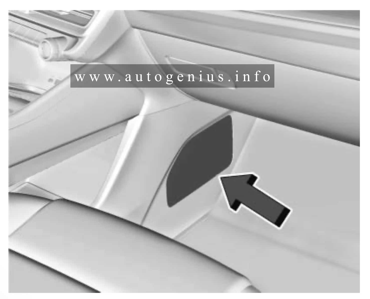
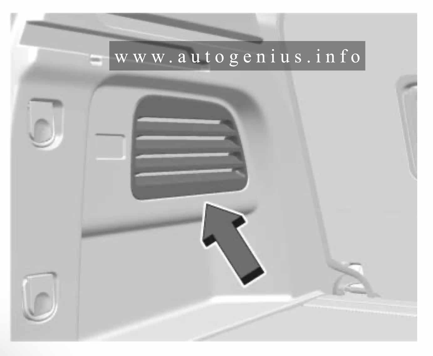
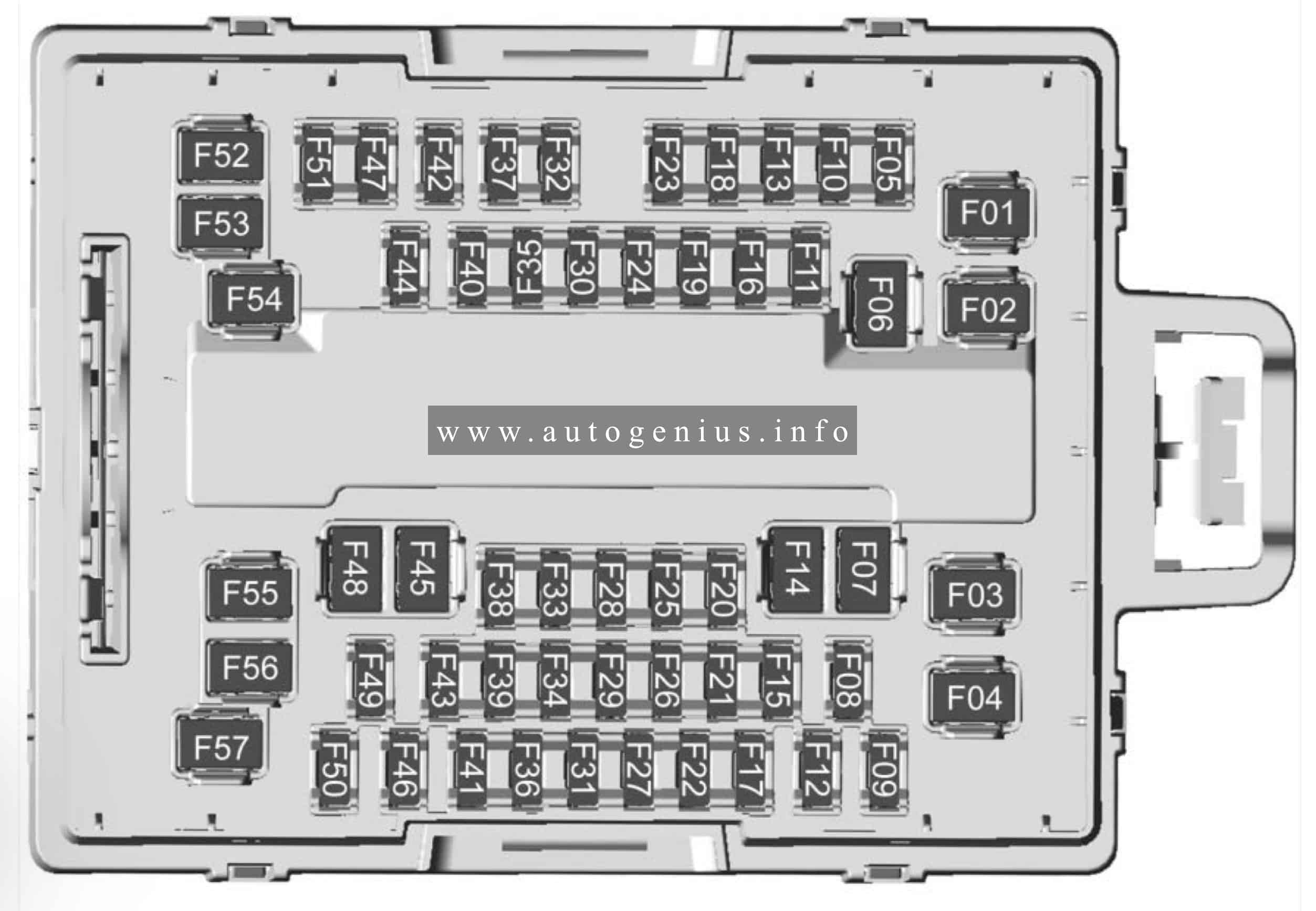
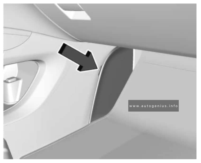
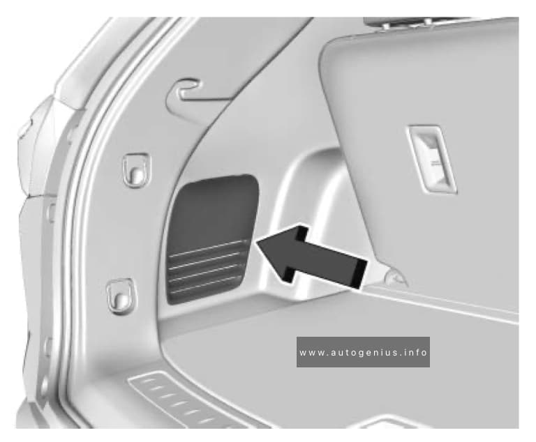
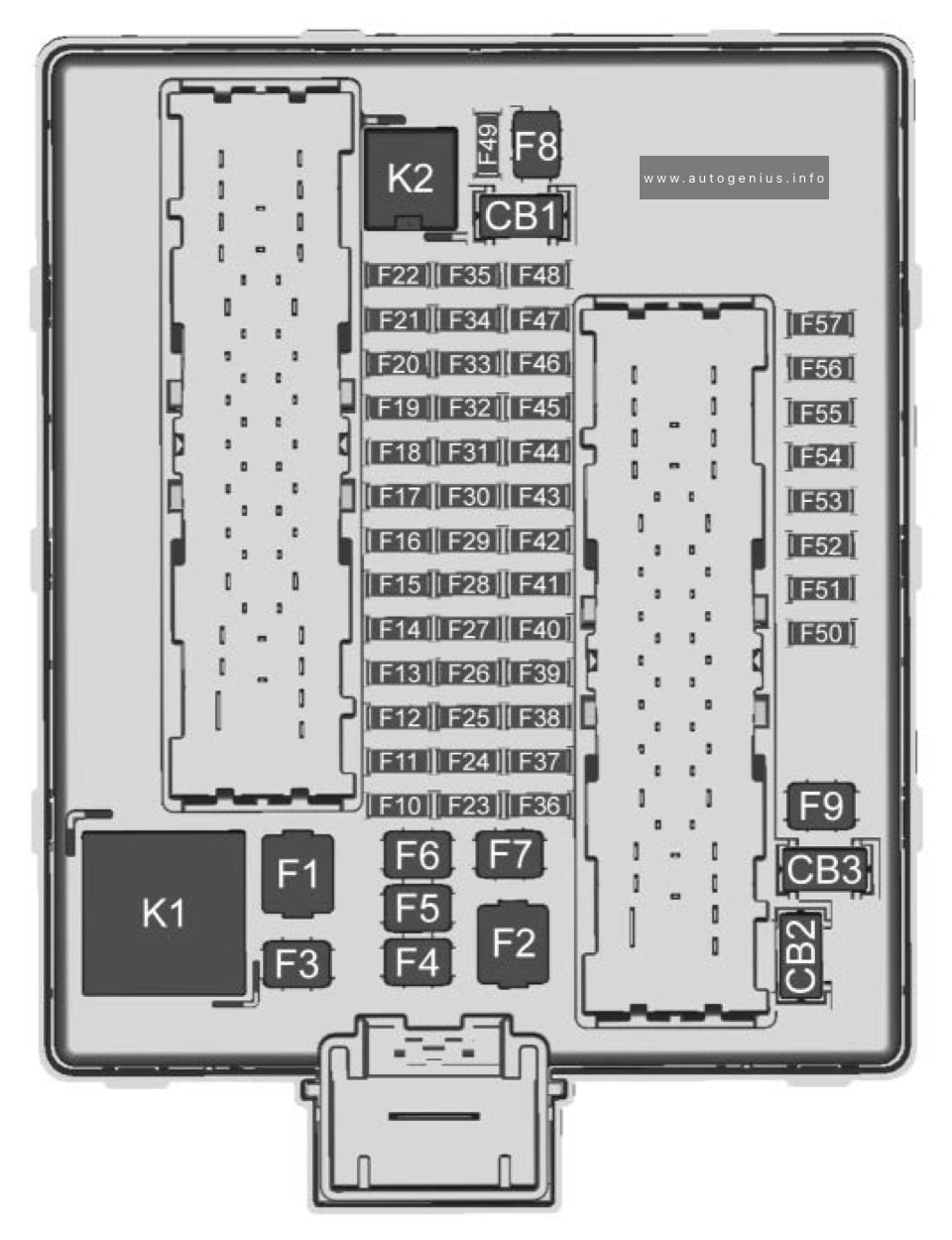
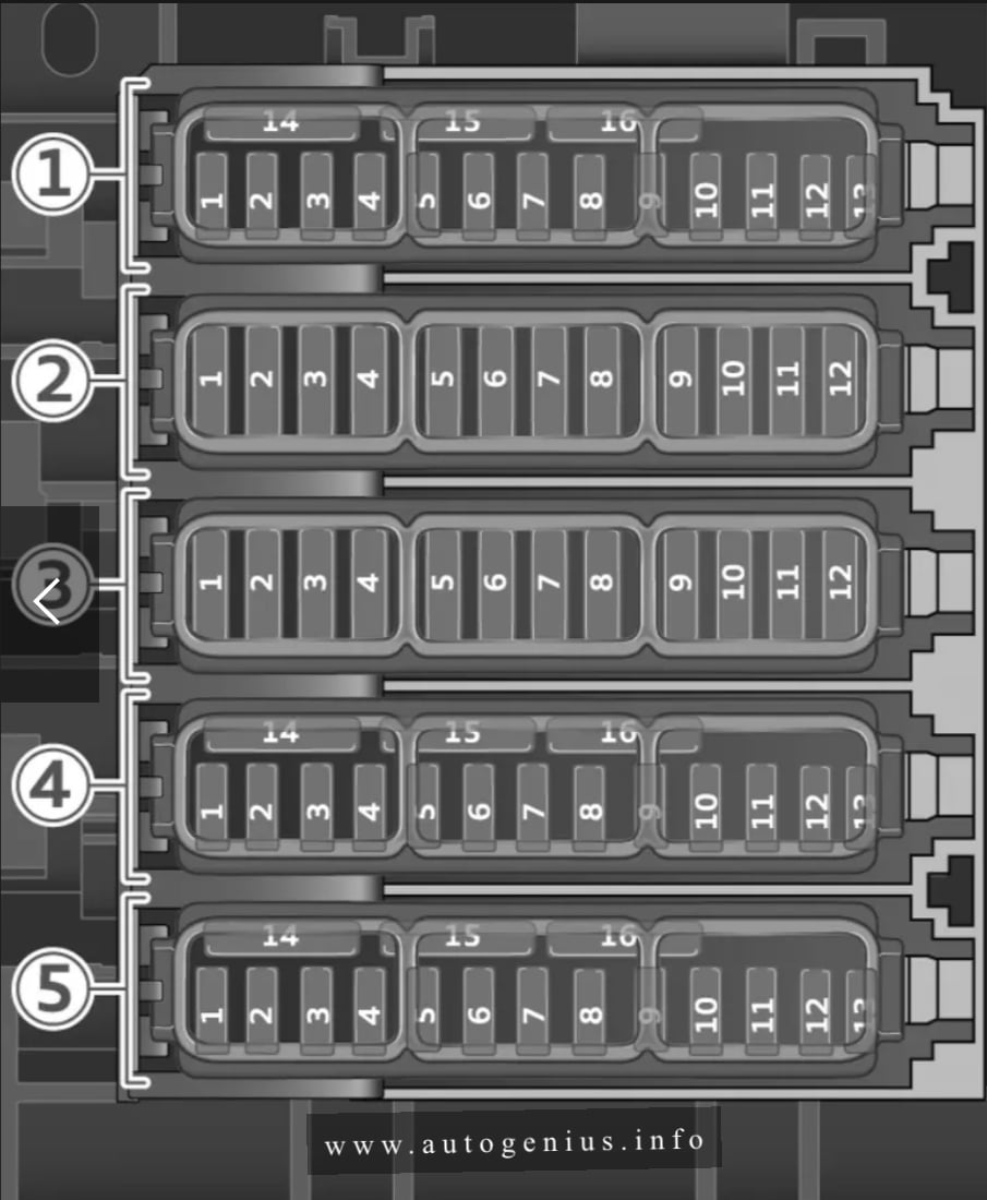
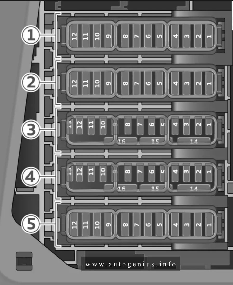
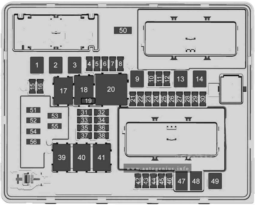
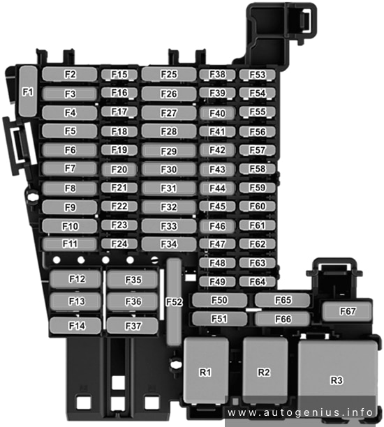
Passenger Compartment
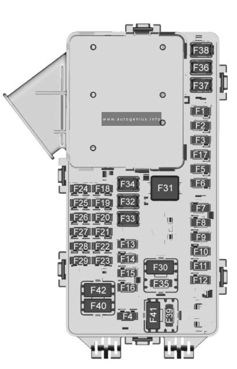
Fuse box diagram
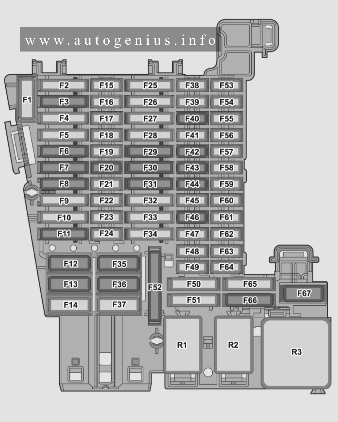
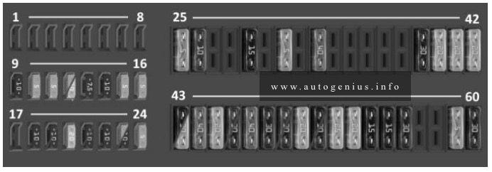
Assignment of the fuses in the passenger compartment
| No. |
A |
Function/component |
| F1 | – | – |
| F2 | 30 | ATO, Rear fresh air control unit |
| F3 | 25 | ATO, Trailer control unit, left (vehicles with factory-fitted towing bracket) |
| F4 | 30 | ATO, Control unit for reduction agent heating [for vehicle with diesel engines] |
| F5 | 25 | ATO, Parking lock actuator |
| F6 | 30 | ATO, Interior lighting, On-board power supply control unit |
| F7 | 30 | ATO, Seat heating, Heating and air conditioning control unit |
| F8 | 25 | ATO, Control unit for special vehicles (depending on the equipment) |
| F9 | 30 | ATO, Driver’s door control unit [for vehicle with left-hand steering], Front passenger’s door control unit [for vehicles with right-hand steering] |
| F10 | 25 | ATO, Control unit for special vehicles |
| F11 | 15 | ATO, Trailer recognition control unit (vehicles with factory-fitted towing bracket) |
| F12 | 40 | MAXI+, Right exterior lighting, On-board power control supply control unit |
| F13 | 40 | MAXI+, Central locking, On-board power control supply control unit |
| F14 | 40 | MAXI+, Interior with socket, 12V/230V |
| F15 | – | – |
| F16 | 7,5 | MINI, Airbag control unit, Seat occupied sensor radio communication control unit |
| F17 | 10 | MINI, Relay for reducing agent dosing system [for vehicles with diesel engines] / Supply module of the reducing agent dosing system [for vehicles with diesel engines] / Recovery tank [for vehicles with diesel engines] |
| F18 | 10 | MINI, Electronic steering column lock control unit / Access and start authorization interface / Anti-theft alarm control unit 2 / Anti-theft alarm control unit 3 / Anti-theft alarm control unit 4 / Anti-theft alarm control unit 5 |
| F19 | 7,5 | MINI, Instrument cluster / Control unit for emergency call module and communication unit |
| F20 | 7,5 | MINI, Telephone, Storage compartment with mobile phone interface / Transmission and reception stabilization control unit / USB port 1 |
| F21 | 7,5 | MINI, Interior lighting relay / Blind spot monitoring control unit / Blind spot monitoring control unit 2 / Around view camera rear view |
| F22 | – | – |
| F23 | 15 | MINI, Contact plate in left B-pillar |
| F24 | 15 | MINI, All-wheel drive control unit |
| F25 | 25 | ATO, Control unit for special vehicles |
| F26 | 30 | ATO, Front passenger door control unit |
| F27 | 25 | ATO, Control unit for special vehicles |
| F28 | – | – |
| F29 | 15 | ATO, Trailer charging cable ( vehicles with factory-fitted towing bracket) |
| F30 | 20 | ATO, Infotainment components, Electronic information system control unit 1 |
| F31 | 25 | ATO, trailer control unit, right (vehicles with factory-fitted towing bracket) |
| F32 | 15 | ATO, Rear lid control unit |
| F33 | 15 | ATO, Contact plate in right B-pillar |
| F34 | – | – |
| F35 | 40 | MAXI+, Left exterior lighting, On-board power supply control unit |
| F36 | 40 | MAXI+, Blower regulator, Supply air fan control unit |
| F37 | – | – |
| F38 | – | – |
| F39 | – | – |
| F40 | 7,5 | MINI, anti-theft alarm |
| F41 | 7,5 | MINI, Data bus diagnostic interface |
| F42 | 7,5 | MINI, Selector lever / Selector lever position indicator |
| F43 | 10 | MINI, Heating and air conditioning control unit / Interior temperature sensor / Rear window heating relay / Tyre pressure monitoring control unit / Auxiliary heater radio signal receiver |
| F44 | 7,5 | MINI, Electromechanical parking brake button / Dash panel switch module, center / Light control panel / Anti-theft alarm sensor / Air humidity, rain and light sensor / Front interior light |
| F45 | 7,5 | MINI, Steering column electronics control unit |
| F46 | 7,5 | MINI, Display for front control, display and information unit |
| F47 | – | – |
| F48 | – | – |
| F49 | – | – |
| F50 | – | – |
| F51 | – | – |
| F52 | 20 | ATO, Cigarette lighter [Optional][5] / 12V socket [Optional][5] / 12V socket 3 [Optional][5] / 12V socket 4 [Optional][5] |
| F53 | – | – |
| F54 | – | – |
| F55 | – | – |
| F56 | – | – |
| F57 | – | – |
| F58 | 7,5 | MINI, Adaptive cruise control unit [Optional] / Parking assistance control unit [Optional] / Front camera for driver assistance systems [Optional] |
| F59 | 7,5 | MINI, Electromechanical parking brake button / Reversing light switch [Optional] / Refrigerant circuit pressure sensor / Socket relay |
| F60 | 7,5 | MINI, Diagnostic connector |
| F61 | 7,5 | MINI, Clutch pedal position sensor [Optional] / Starter relay 1 / Starter relay 2 |
| F62 | 7,5 | MINI, USB charging socket 1 [Optional] |
| F63 | – | – |
| F64 | – | – |
| F65 | – | – |
| F66 | 15 | ATO, Rear window wiper. |
| F67 | 30 | MAXI+, Rear window heating |
| R1 | Socket relay | |
| R2 | Power supply relay terminal 15 | |
| R3 | Rear window heating relay | |
| R4 | Relay for reducing agent dosing system [for cars with diesel engine] |
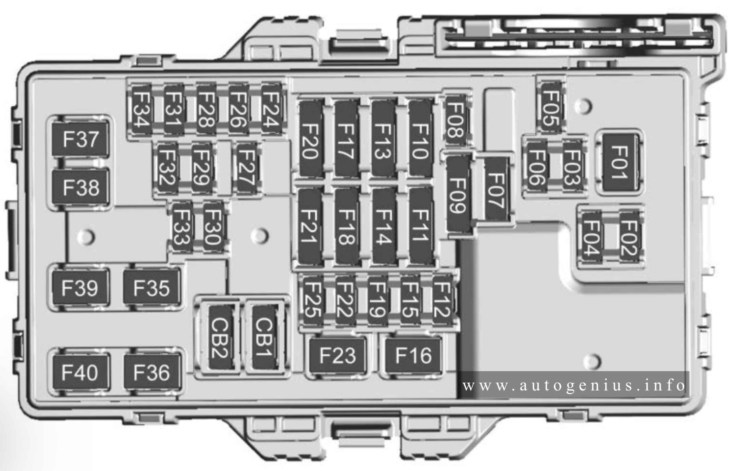
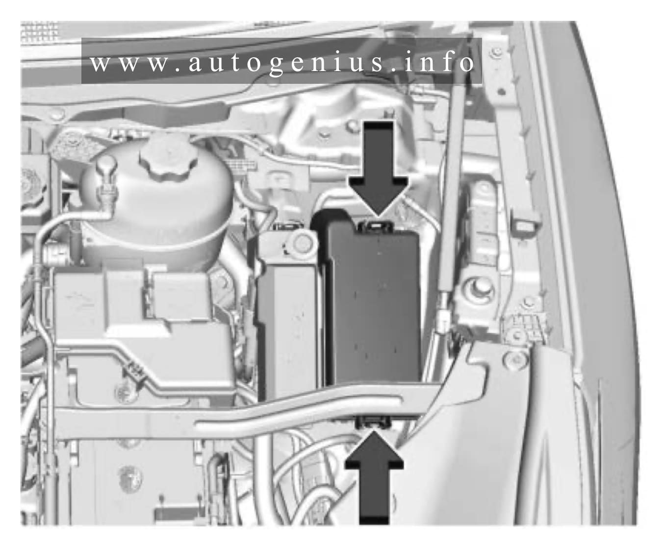
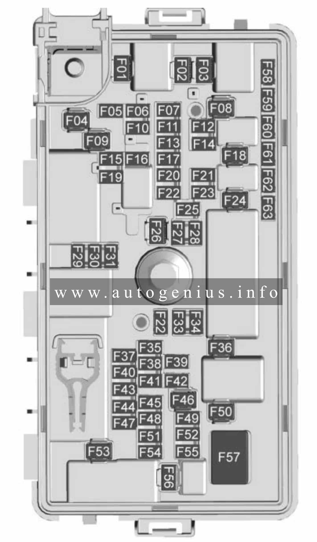
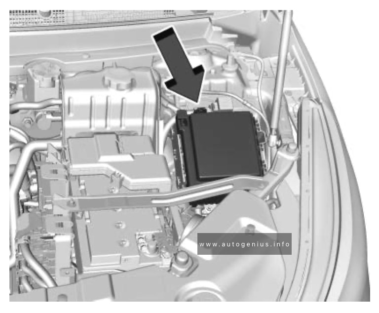
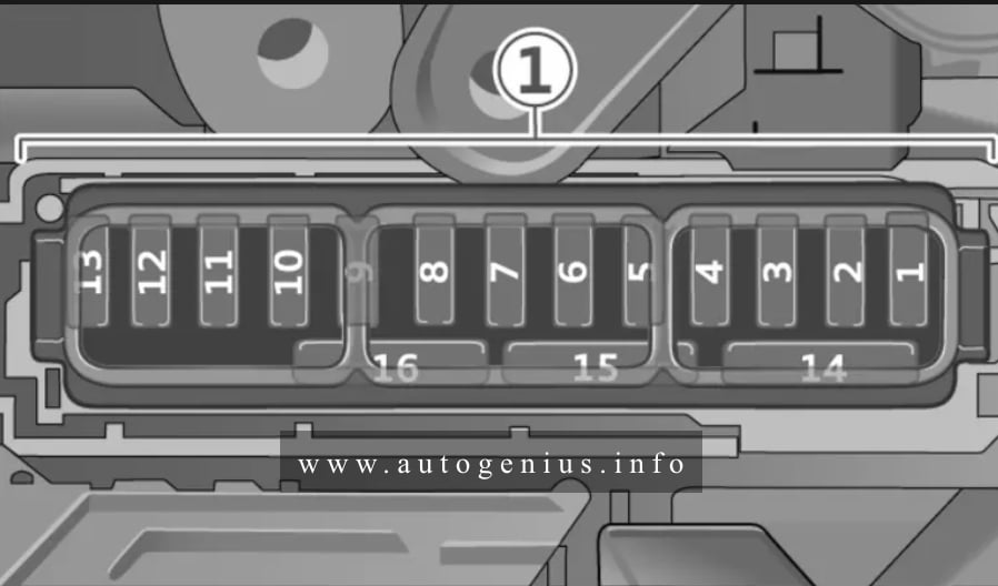
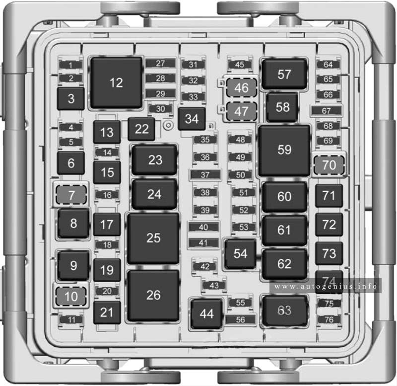
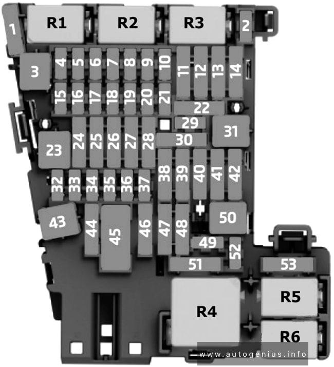
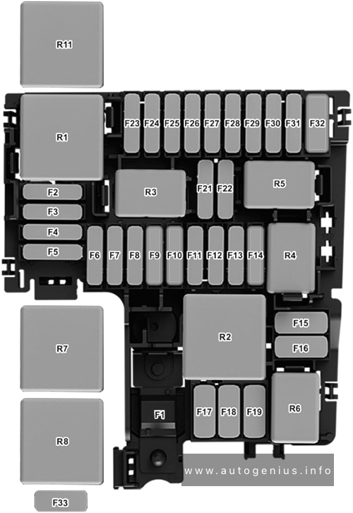
Engine Comparment
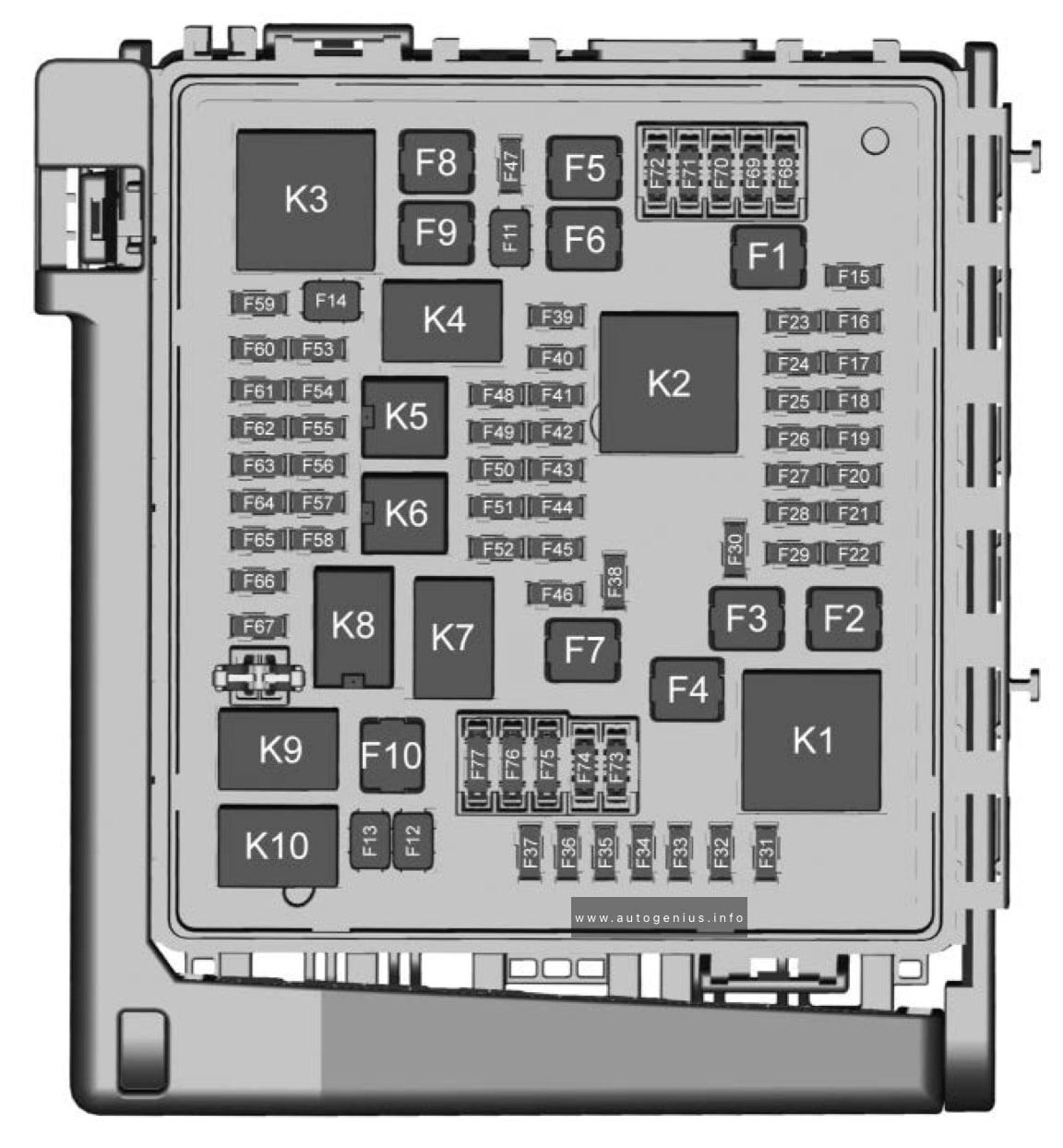
Fuse box diagram
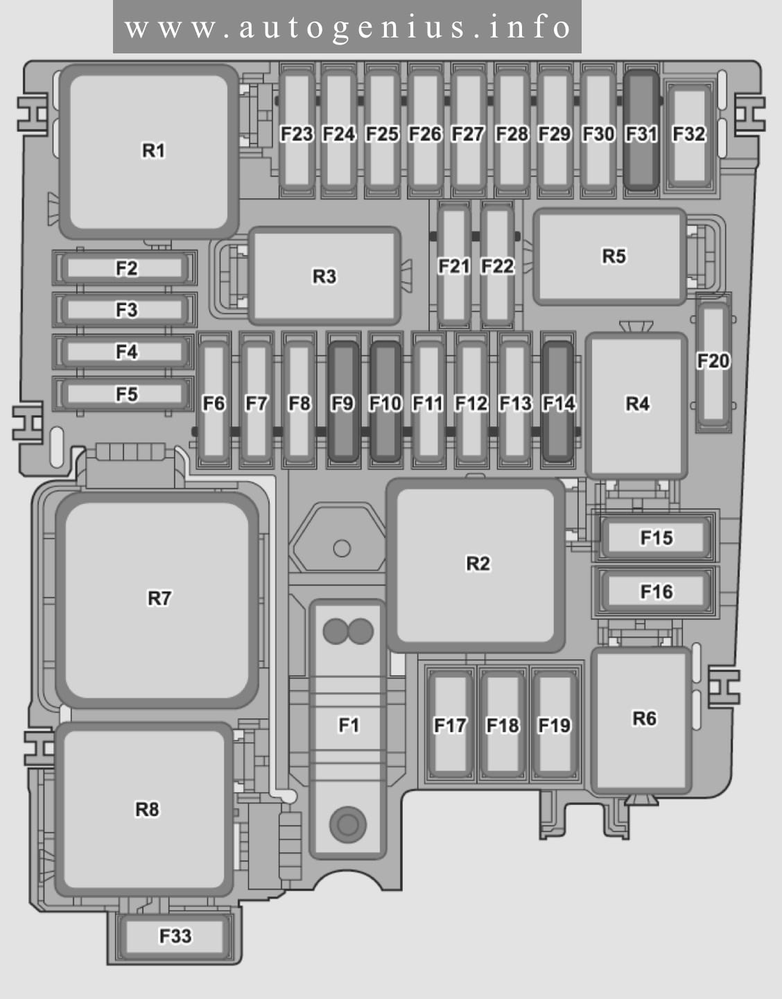
Assignment of the fuses in the engine compartment
| No. |
A |
Function/component |
| F1 | 80 | MIDI, Power steering control unit |
| F2 | 7,5 | ATO, ABS control unit / Main relay [for cars with a gasoline engine] / Terminal 30 power supply relay [for vehicles with diesel engines] / Engine control unit |
| F3 | 7,5 | ATO, [with engine letter designation DHFA] Shut-off and safety valve 1 for gas cylinder / Shut-off and safety valve 2 for gas cylinder / Shut-off and safety valve 3 for gas cylinder / Shut-off and safety valve 4 for gas cylinder / Shut-off and safety valve 5 for gas cylinder |
| F4 | 15 | ATO, Headlight front left |
| F5 | 15 | ATO, Headlight front right |
| F6 | – | – |
| F7 | 30 | ATO, Gearbox oil cooling pump [Optional] |
| F8 | 40 | ATO, Brake booster |
| F9 | 15 | ATO, Horn relay |
| F10 | 30 | ATO, Windscreen wiper motor relay 1 / Windscreen wiper motor relay 2 / Windscreen wiper motor |
| F11 | – | – |
| F12 | 15 | ATO, Mechatronic unit DSG gearbox [Optional] |
| F13 | 25 | ATO, ABS control unit |
| F14 | 20 | ATO, Additional heater control unit [Optional] |
| F15 | 40 | ATO, ABS control unit |
| F16 | – | – |
| F17 | 40 | MAXI, Heating element for additional air heater [for vehicles with diesel engines] |
| F18 | 40 | MAXI, Heating element for additional air heater [for vehicles with diesel engines] |
| F19 | – | – |
| F20 | – | – |
| F21 | 7,5 | ATO, Engine control unit |
| F22 | 30 | Starter |
| F23 | 15 | ATO, Engine control unit |
| F24 | 7,5 | ATO, [for vehicles with diesel engines] Oil level and temperature sensor [for vehicles with diesel engines] / Fuel pump relay [for vehicles with diesel engines] / Activated carbon filter solenoid valve 1 [for vehicles with diesel engines] / Exhaust camshaft adjuster valve 1 [for vehicles with diesel engines] / Oil pressure regulating valve [for vehicles with diesel engines] / Inlet camshaft adjuster cylinder 2 [for vehicles with diesel engines] / Exhaust camshaft adjuster cylinder 2 [for vehicles with diesel engines] / Inlet camshaft adjuster cylinder 3 [for vehicles with diesel engines] / Exhaust camshaft adjuster cylinder 3 [for vehicles with diesel engines] / Inlet camshaft adjuster valve 1 [for vehicles with diesel engines] / Radiator fan [for vehicles with diesel engines] |
| F24 | 10 | ATO, for cars with a gasoline engine] Oil level and temperature sender [for cars with a gasoline engine] / Glow plug control unit [for cars with a gasoline engine] / Reducing agent preheating control unit [for cars with a gasoline engine] / Reducing agent metering system relay [for cars with a gasoline engine] / Fuel pressure regulator [for cars with a gasoline engine] / Fuel metering valve [for cars |
| F25 | 7,5 | ATO, Injector cylinder 1 / Injector cylinder 2 / Injector cylinder 3 / Injector cylinder 4 |
| F26 | 10 | ATO, Crankcase ventilation heating resistor [for vehicles with diesel engines] / Oil pressure regulating valve [for vehicles with diesel engines] / Coolant regulating valve [for vehicles with diesel engines] / Piston cooling nozzle control valve [for vehicles with diesel engines] / Heater circulation pump [for vehicles with diesel engines] / Charge air cooling pump [for cars with a gasoline engine] / |
| , F27 | 10 | ATO, [for cars with a gasoline engine] Lambda probe 1 after neutralizer [for cars with a gasoline engine] / Lambda probe 1 before neutralizer [for cars with a gasoline engine] |
| F27 | 15 | ATO, [for vehicles with diesel engines] Soot Particle Sensor [for vehicles with diesel engines] / NOx Sensor 3 [for vehicles with diesel engines] / Lambda Probe 1 Before Catalytic Converter [for vehicles with diesel engines] / NOx Sensor Control Unit [for vehicles with diesel engines] / NOx Sensor Control Unit 2 [for vehicles with diesel engines] |
| F28 | 20 | ATO, Ignition coil 1 with output stage [for cars with a gasoline engine] / Ignition coil 2 with output stage [for cars with a gasoline engine] / Ignition coil 3 with output stage [for cars with a gasoline engine] / Ignition coil 4 with output stage [for cars with a gasoline engine] |
| F29 | 15 | ATO, [for cars with a gasoline engine] Fuel pump control unit / Fuel delivery module |
| F29 | 20 | ATO [for vehicles with diesel engines] |
| F30 | – | – |
| F31 | 7,5 | ATO, brake light sensor |
| F32 | – | – |
| F33 | 40 | MAXI, Heating element for additional air heater [for vehicles with diesel engines] |
| F34 | 30 | ATO, Heated windscreen relay [for cars with heated windshield] / Windscreen heating element [for cars with heated windshield] / Relay 2 for heated windscreen [for cars with heated windshield] |
| F35 | 30 | Relay 2 for heated windscreen [for cars with heated windshield] / Windscreen heating element [for cars with heated windshield] |
| R1 | Main relay [for cars with petrol engines], Power supply relay terminal 30 [for cars with diesel engine] | |
| R2 | High Power Heating Relay | |
| R3 | ||
| R4 | Starter relay 1 | |
| R5 | Starter relay 2 | |
| R6 | Fuel pump relay/ Gas shut-off valve relay [with engine letter designation DHFA] | |
| R7 | Glow plug control unit [for cars with diesel engine] | |
| R8 | Low power heating relay [for vehicles with additional air heater heating element] | |
| R9 | Heated windscreen relay | |
| R10 | Relay 2 for heated windscreen | |
| R11 | Relay 1 windscreen wiper motor | |
| R12 | Windscreen wiper motor relay 2 |
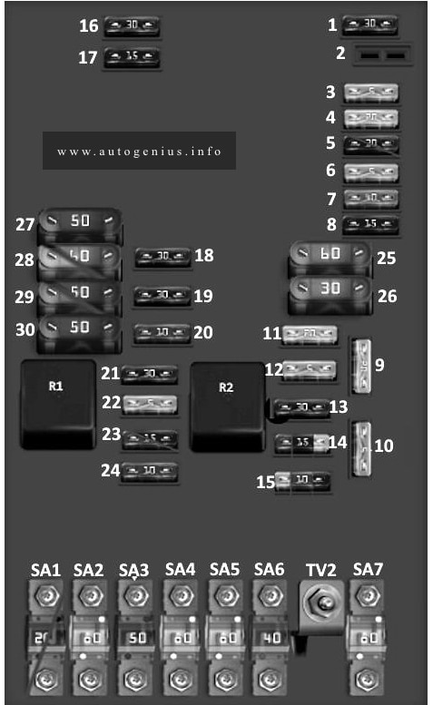
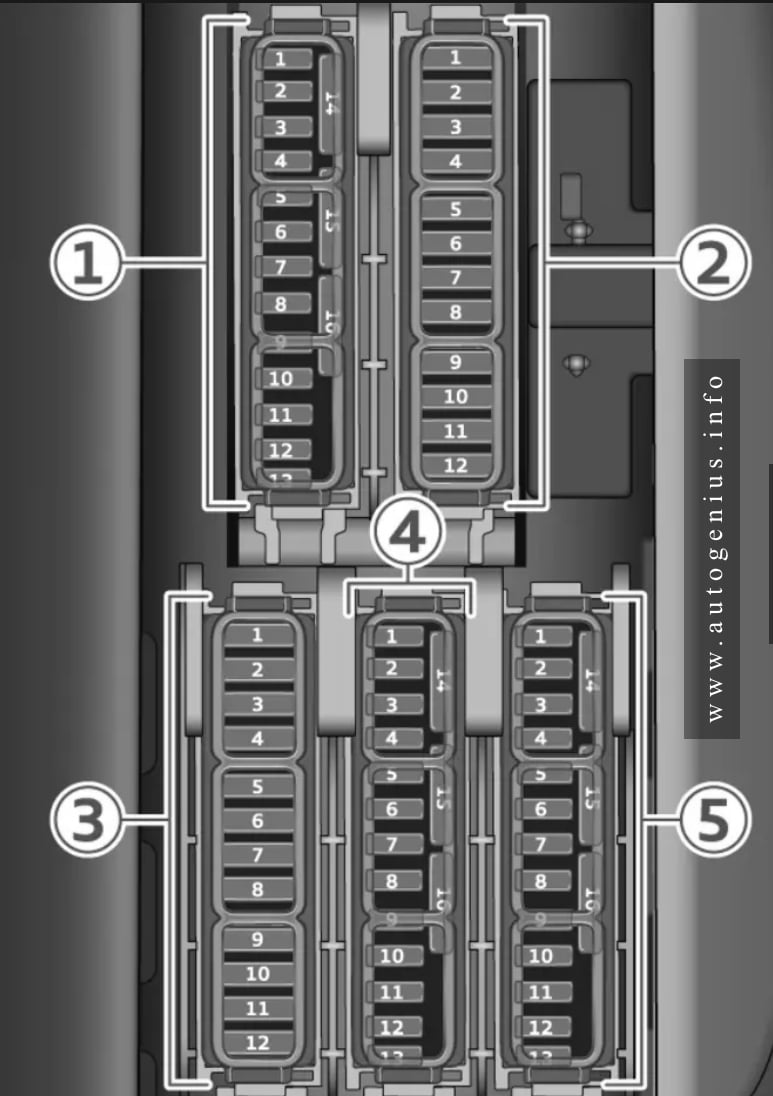
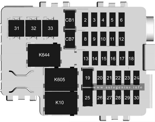
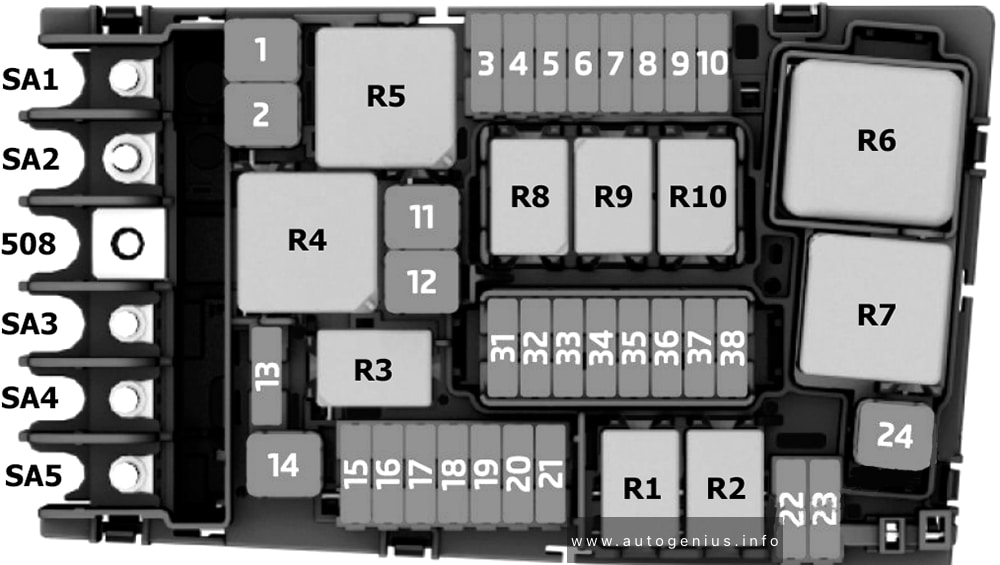
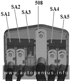
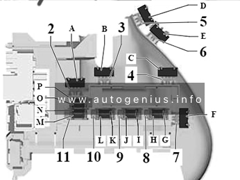
Fuses for junction box 1 (SX1)
Assignment of the fuses in the juncion box 1 (SX1)
| Type | No. | Function/component |
| Battery Terminal | SA1 | Fuse box B |
| Battery Terminal | SA2 | Radiator Fan [for vehicle with a simple radiator fan] |
| Battery Terminal | SA2 | Radiator Fan [for vehicle with dual radiator fan] |
| Battery Terminal | 508 | Switching and distribution box 2/ Battery |
| Battery Terminal | SA4 | Fuse box C |
| Battery Terminal | SA5 | Fuse box C |
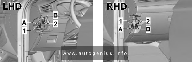
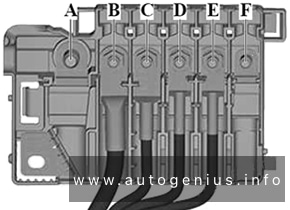
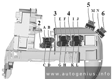
Fuses for junction box 2 (SX2)
Assignment of the fuses in the juncion box 2 (SX2)
| Type | No. | Function/component |
| MIDI | A | Starter/ Generator with voltage regulator |
| MIDI | B | Relay and fuse block J for special vehicle [for cars with preparation for a 2nd battery] |
There are also videos on this topic on our YouTube channel.
WARNING: Terminal and harness assignments for individual connectors will vary depending on vehicle equipment level, model, and market.