Volkswagen Jetta (V, Type 1K; 2005 – 2010) – fuse and relay box diagram
Year of production: 2005, 2006, 2007, 2008, 2009, 2010
The Volkswagen Jetta was a compact family car produced from 1992 to 1999. In this article, you will find fuse box diagrams for Volkswagen Jetta V, type 1K models from 2005 to 2010, along with details on the fuse panel locations inside the vehicle and the specific functions of each fuse (fuse layout) and relay.
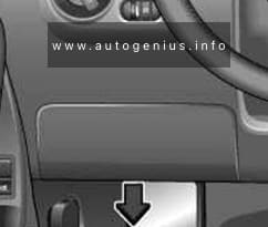
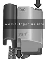
Fuse box location
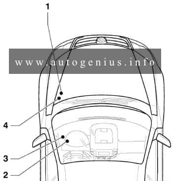
- Engine compartment fuse box
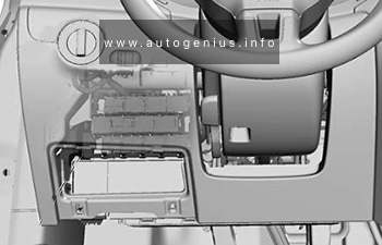
- Relay carrier on onboard supply control unit (left under dash panel)
- The instrument panel fuse panel
- Additional relay carrier, under box in engine compartment
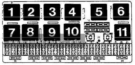
Passenger compartment
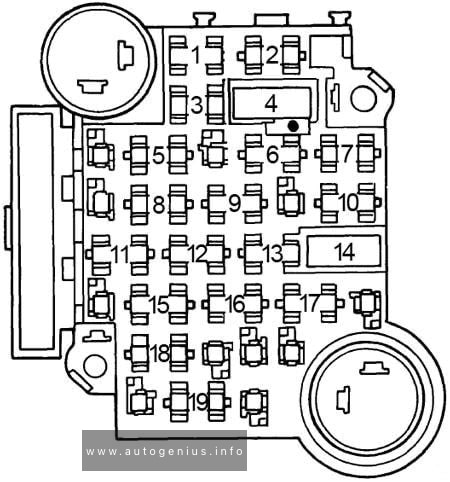
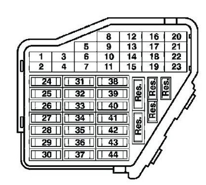
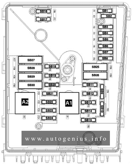
Fuse box diagram
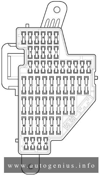
Assignment of the fuses and relays in the passenger compartment
| No. |
A |
Function/component |
| 1 | 10 | T16 – Diagnostic connection (T16/1) J623 – Engine control unit J757 – Engine component current supply relay (167) (from May 2005) J538 – Fuel pump control unit (from May 2005) J485 – Relay for auxiliary heater operation (from 2006) N79 – Heater element for crankcase breather (from 2006) G70 – Air mass meter (from 2006) J431 – Control unit for headlight range control (from 2006) |
| 2 | 5 | J104 – ABS control unit E132 – Traction control system switch E256 – TCS and ESP button E492 – Tyre pressure monitor display button F – Brake light switch (low; from November 2005) |
| 10 | J623 – Engine control unit (from 2006) V49 – Right headlight range control motor (from 006) V48 – Left headlight range control motor (from 2006) E102 – Headlight range control regulator (from 2006) J538 – Fuel pump control unit (from 2006) J345 – Trailer detector control unit (from 2006) J587 – Selector lever sensors control unit (from 2006) J533 – Data bus diagnostic interface (from 2006) J285 – Control unit in dash panel insert (from 2006) J500 – Power steering control unit (from 2006) J104 – ABS with EDL control unit (from 2006) E132 – Traction control system switch (from 2006) E256 – TCS and ESP button (from 2006) G476 – Brake pedal position sender (from 2006) E1 – Light switch (from 2006) F47 – Brake pedal switch, (from November 2005) |
|
| 3 | 10 | J500 – Power steering control unit (up to May 2005) |
| 5 | J234 – Airbag control unit (from May 2005) | |
| 4 | 5 | E16 – Heater/heat output switch G65 – High-pressure sender J131 – Heated driver seat control unit J132 – Heated front passenger seat control unit J255 – Climatronic control unit K216 – Stabilisation program warning lamp 2 (from May 2005) M17 – Reversing light bulb (from May 2005) E422 – Tyre pressure monitor display button (from May 2005) G266 – Oil level and oil temperature sender (high; from May 2005) J530 – Garage door operation control unit (from May 2006) G128 – Seat occupied sensor, front passenger side (from May 2006) Y7 – Automatic anti-dazzle interior mirror (from May 2006) Z20 – Left washer jet heater element (from May 2006) Z21 – Right washer jet heater element (from May 2006) |
| 10 | G266 – Oil level and oil temperature sender (high; from November 2005) M17 – Reversing light (high; from November 2005) J255 – Climatronic control unit (high; from November 2005) G65 – High-pressure sender (high; from November 2005) E16 – Switch for heater and heater output (high; from November 2005) J530 – Garage door operation control unit (high; from November 2005) N253 – Battery isolation igniter (high; from November 2005) Y7 – Automatic anti-dazzle interior mirror (high; from November 2005) E422 – Tyre pressure monitor display button (high; from November 2005) K216 – Stabilisation programme warning lamp 2 (high; from November 2005) Z20 – Left washer jet heater element (high; from November 2005) Z21 – Right washer jet heater element (high; from November 2005) L71 – Illumination for traction control system switch (high; from November 2005) J301 – Air conditioning system control unit (high; from May 2007) |
|
| 5 | 5 | F47 – Cruise control system brake pedal switch (to May 2005) G476 – Clutch position sender J431 – Control unit for headlight range control (from May 2005) J500 – Power steering control unit (from May 2005) J745 – Cornering light and headlight range control unit, on right headlight, (high; December 2006) |
| 10 | J745 – Cornering light and headlight range control unit, on right headlight (low; from May 2006), (high; from May 2007) | |
| 6 | 5 | J285 – Control unit in dash panel insert (up to May 2006) J538 – Fuel pump control unit (up to May 2006) J533 – Data bus diagnostic interface (up to May 2006) F125 – Multifunction switch (up to May 2006) J587 – Selector lever sensors control unit (up to May 2006) F189 – Tiptronic switch (up to May 2006) J745 – Cornering light and headlight range control unit, on left of headlight (high; December 2006) |
| 10 | J745 – Cornering light and headlight range control unit, on left headlight (low; from May 2006), (high; from May 2007) | |
| 7 | 5 | J431 – Control unit for headlight range control (to May 2005) Y7 – Automatic anti-dazzle interior mirror (from May 2005) Not assigned (from May 2006) |
| 8 | 5 | Y7 – Automatic anti-dazzle interior mirror (to May 2005) |
| 10 | J345 – Trailer detector control unit (from May 2005) Not assigned (from May 2006) |
|
| 9 | 5 | Not assigned (to May 2005) J503 – Control unit with display for radio and navigation system (only commercial navigation system unit) (from May 2005) Not assigned (from May 2006) |
| 10 | 5 | J412 – Mobile telephone operating electronics control unit (to May 2005) J530 – Garage door operation control unit (from May 2005) J706 – Seat occupied recognition control unit (from May 2005) Not assigned (from May 2006) |
| 11 | 5 | J345 – Trailer detector control unit (to May 2005) Not assigned (from May 2005) |
| 10 | J745 – Cornering light and headlight range control unit, on right headlight, (from May 2007) | |
| 12 | 10 | J386 – Driver door control unit J387 – Front passenger door control unit |
| 13 | 10 | E1 – Light switch T16 – Diagnostic connection (T16/16) F47 – Brake pedal switch (from May 2005) G397 – Sensor for rain and light detection (from 2006) G197 – Magnetic field sender for compass (from 2006) |
| 14 | 5 | F – Brake light switch (low; from May 2005) J217 – Automatic gearbox control unit |
| 10 | J587 – Selector lever sensors control unit (from 2006) R149 – Remote control receiver for auxiliary coolant heater (from 2006) J301 – Air conditioning system control unit (from 2006) J255 – Climatronic control unit (from 2006) E16 – Heater/heat output switch (from 2006) J446 – Parking aid control unit (from 2006) J104 – ABS with EDL control unit (from 2006) E94 – Heated driver seat regulator (from 2006) E95 – Heated front passenger seat regulator (from May 2006) J217 – Automatic gearbox control unit (from November 2005) |
|
| 15 | 7.5 | J519 – Onboard supply control unit (interior illumination) |
| 16 | 10 | E16 – Heater/heat output switch J301 – Air conditioning system control unit J255 – Climatronic control unit R149 – Remote control receiver for auxiliary coolant heater Not assigned (from May 2006) |
| 5 | J515 – Aerial selection control unit (high; from November 2005) | |
| 17 | 5 | G397 – Rain and light detector sensor (up to May 2006) J515 – Aerial selection control unit (up to May 2006) G273 – Interior monitoring sensor (from 2006) G384 – Vehicle inclination sender (from 2006) H12 – Alarm horn (from 2006) |
| 18 | 5 | J446 – Parking aid control unit J587 – Selector lever sensors control unit Not assigned (from 2006) |
| 19 | 5 | J754 – Accident data memory |
| 20 | 5 | J104 – ABS with EDL control unit Not assigned (from 2006) |
| 21 | 5 | J503 – Control unit with display for radio and navigation system (only commercial navigation system unit) (up to May 2005) Not assigned (from May 2005) J542 – Control unit for engine speed governor, in front left footwell (special vehicles) (high; from May 2007) J378 – PDA control unit (special vehicles) (from May 2007) |
| 22 | 40 | V2 – Fresh air blower (Climatronic) N253 – Battery isolation igniter (rear battery) (high; from May 2005) |
| 23 | 30 | J386 – Driver door control unit (window regulator) J387 – Front passenger door control unit (window regulator) |
| 24 | 25 | U1 – Cigarette lighter (up to May 2006) U9 – Rear cigarette lighter (up to May 2006) U5 – 12 V socket (criminal investigation department) |
| 20 | J388 – Rear left door control unit (central locking) (from 2006) J389 – Rear right door control unit (central locking) (from 2006) J393 – Convenience system central control unit (from 2006) |
|
| 25 | J388 – Rear left door control unit (central locking) (high; from May 2007) J389 – Rear right door control unit (central locking) (high; from May 2007) J393 – Convenience system central control unit (high; from May 2007) |
|
| 25 | 25 | Z1 – Heated rear window J301 – Air conditioning system control unit (only with auxiliary coolant heater) E16 – Heater/heat output switch (only with auxiliary coolant heater) N24 – Fresh air blower series resistor (only with auxiliary coolant heater) |
| 26 | 20 | U5 – 12 V socket (luggage compartment) (up to May 2006) |
| 30 | J388 – Rear left door control unit (window regulator) (from May 2006) J389 – Rear right door control unit (window regulator) (from May 2006) |
|
| 27 | 15 | J538 – Fuel pump control unit G6 – Fuel system pressurisation pump J17 – Fuel pump control unit J643 – Fuel supply relay (from May 2006) |
| 28 | 10 | Charging point for Mag- Lite electric torch (special vehicle interface) (up to May 2005) |
| 30 | U13 – Transformer with socket, 12V-230V (from May 2005) Not assigned (from May 2006) |
|
| 25 | Special vehicles socket (not for USA/Canada ) (high; from November 2005) | |
| 29 | 10 | J220/J623 – Motronic control unit J248/J623 – Diesel direct injection system control unit G70 – Air mass meter (AXX) N79 – Heater element for crankcase breather (BUB, BMJ) Not assigned (from 2006) |
| 30 | 5 | J234 – Airbag control unit (to May 2005) K145 – Front passenger side airbag deactivated warning lamp (to May 2005) |
| 10 | N30 – Injector, cylinder 1 (from May 2005) N31 – Injector, cylinder 2 (from May 2005) N32 – Injector, cylinder 3 (from May 2005) N33 – Injector, cylinder 4 (from May 2005) |
|
| 20 | N30 – Injector, cylinder 1 N31 – Injector, cylinder 2 N32 – Injector, cylinder 3 N33 – Injector, cylinder 4 N83 – Injector, cylinder 5 N84 – Injector, cylinder 6 J217 – Automatic gearbox control unit (from 2006) J743 – Mechatronics for direct shift gearbox (from 2006) |
|
| 31 | 5 | F4 – Reversing light switch (up to May 2005) J743 – Mechatronics for direct shift gearbox (up to May 2005) |
| 20 | V192 – Vacuum pump for brakes (from May 2005) | |
| 32 | 30 | J388 – Rear left door control unit (window regulator) (up to May 2006) J389 – Rear right door control unit (window regulator) (up to May 2006) U13 – Transformer with socket, 12V-230 V (from May 2006) U27 – Transformer with socket, 12V- 15 V, (USA/Canada) (from May 2006) |
| 33 | 25 | J245 – Sliding sunroof adjustment control unit |
| 34 | 15 | V125 – Driver seat lumbar support longitudinal adjustment motor V126 – Front passenger seat lumbar support longitudinal adjustment motor V129 – Driver seat lumbar support height adjustment motor V130 – Front passenger seat lumbar support height adjustment motor |
| 35 | 5 | G273 – Interior monitoring sensor G384 – Vehicle inclination sender H12 – Alarm horn Not assigned (from 2006) |
| 36 | 20 | V11 – Headlight washer system pump J39 – Headlight washer system relay |
| 37 | 30 | J131 – Heated driver seat control unit J132 – Heated front passenger seat control unit |
| 38 | 10 | J23 – Rotating light and siren system control unit (up to May 2005) Not assigned (from May 2005) J745 – Cornering light and headlight range control unit, on left headlight, (from May 2007) |
| 20 | J388 – Rear left door control unit (central locking), NAR, with alarm horn relay J641) (from May 2006) J389 – Rear right door control unit (central locking), NAR, with alarm horn relay J641) (from May 2006) J393 – Convenience system central control unit (only VR6) (from May 2006) |
|
| 39 | 20 | Not assigned (up to May 2005) J217 – Automatic gearbox control unit (from May 2005) Not assigned (from May 2006) |
| 40 | 40 | E16 – Heater/heat output switch (fresh air blower) J301 – Air conditioning system control unit (fresh air blower) |
| 5 | E16 – Heater/heat output switch (fresh air blower) (high; from November 2005) J301 – Air conditioning system control unit (fresh air blower) (high; from November 2005) |
|
| 41 | 15 | V12 – Rear window wiper motor (up to May 2006) |
| 20 | V12 – Rear window wiper motor (from May 2006) J519 – Onboard supply control unit (double washer pump) (BSG J1) (from May 2006) |
|
| 42 | 15 | J729 – Double washer pump relay 1 (to May 2005) J730 – Double washer pump relay 2 (to May 2005) J519 – Onboard supply control unit (double washer pump) (BSG J1) (from May 2005) |
| 20 | U1 – Cigarette lighter (from May 2006) U9 – Rear cigarette lighter (from May 2006) U5 – 12 V socket (criminal investigation department) (from May 2006) |
|
| 43 | 15 | J345 – Trailer detector control unit |
| 44 | 20 | J345 – Trailer detector control unit |
| 45 | 15 | J345 – Trailer detector control unit |
| 46 | 5 | Z20 – Left washer jet heater element Z21 – Right washer jet heater element E94 – Heated driver seat regulator E95 – Heated front passenger seat regulator Not assigned (from May 2006) |
| 47 | 5 | J485 – Auxiliary heater operation relay Not assigned (from May 2006) |
| 48 | 10 | Not assigned (to May 2005) Charger for Mag-Lite and hand-held two-way radio (from May 2005) |
| 49 | 5 | E1 – Lighting switch Not assigned (from May 2006) |
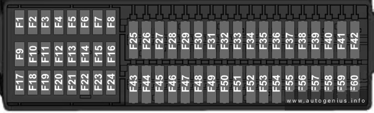
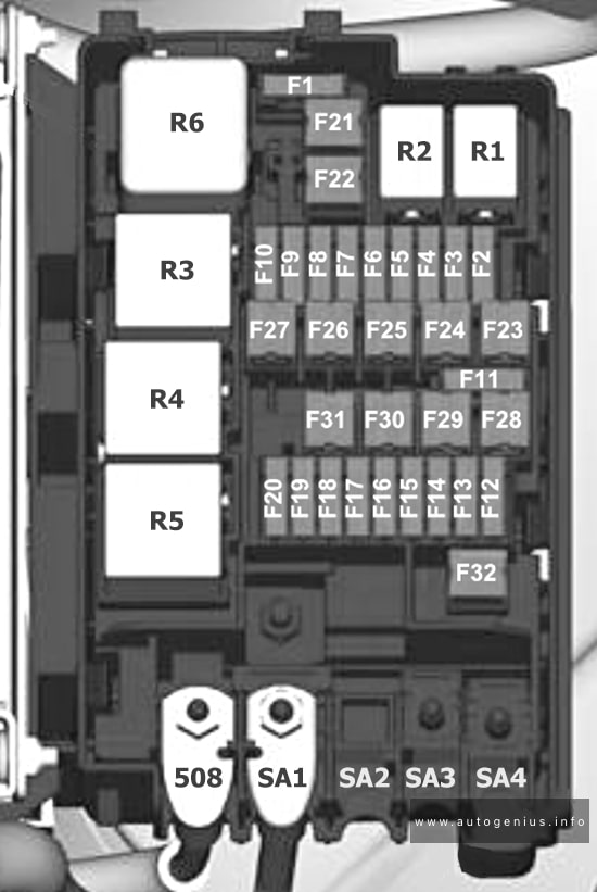
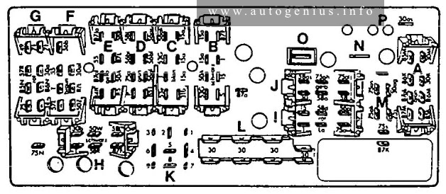
Engine compartment
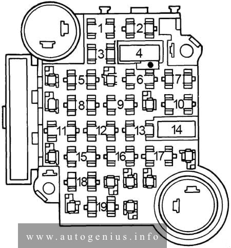
Fuse box diagram (low)
Assignment of the fuses and relays in the engine compartment (low)
| No. |
A |
Function/component |
| F1 | 20 | J393 – Convenience system central control unit Not assigned (from May 2006) |
| F2 | 5 | J527 – Steering column electronics control unit |
| F3 | 5 | J519 – Onboard supply control unit |
| F4 | 30 | J104 – ABS control unit |
| F5 | 15 | J743 – Mechatronic control unit (up to May 2006), (from May 2007) |
| 30 | J743 – Mechatronic control unit (from May 2006) J285 – Control unit in dash panel insert (from May 2006) |
|
| F6 | 5 | J285 – Control unit in dash panel insert |
| F7 | 15 | J608 – Special vehicle control unit |
| 25 | J608 – Special vehicle control unit (from May 2006) | |
| 30 | J743 – Mechatronics control unit (0AM) (from May 2007) | |
| F8 | 15 25 |
J503 – Control unit with display for radio and navigation R – Radio R – Preparation for radio and navigation system with TV (models for Japan) |
| F9 | 5 | J412 – Mobile telephone operating electronics control unit |
| F10 | 5 | J317 – Terminal 30 voltage supply relay |
| 10 | J623 – Engine control unit | |
| 5 | J359 – Low heat output relay | |
| F11 | 20 | J364 – Auxiliary heater control unit |
| F12 | 5 | J533 – Data bus diagnostic interface |
| F13 | 30 | J623 – Engine control unit (only models with diesel engine) J623 – Engine control unit (petrol) (from May 2007) |
| 25 | J623 – Petrol engine control unit (only models with petrol engine) (up to May 2007) | |
| F14 | 20 | N152 – Ignition transformer N70-N323 – Ignition coils with output stage |
| F15 | 10 | Z62 – Lambda probe heater 3 Z19 – Lambda probe heater G39 – Lambda probe G108 – Lambda probe 2 before catalytic converter G130 – Lambda probe after catalytic converter |
| 5 | G131 – Lambda probe 2 after catalytic converter G287 – Lambda probe 3 after catalytic converter J17 – Fuel pump relay J179 – Automatic glow period control unit J360 – High heat output relay (370) |
|
| F16 | 30 | J104 – ABS control unit |
| F17 | 15 | H2 – Treble tone horn H7 – Bass tone horn J519 – Onboard supply control unit (from May 2006) |
| F18 | 30 | J608 – Special vehicle control unit (up to May 2006) R12 – Amplifier |
| F19 | 30 | J400 – Wiper motor control unit V216 – Driver side windscreen wiper motor |
| F20 | 40 | Not assigned (up to May 2006) J179 – Automatic glow period control unit (SDI) (from May 2006) |
| 10 | V50 – Continued coolant circulation pump (from May 2007) | |
| F21 | 15 | Z19 – Lambda probe heater (up to May 2006) G39 – Lambda probe (up to May 2006) G130 – Lambda probe after catalytic converter (up to May 2006) J583 – NOx sensor control unit (up to May 2006) |
| 10 | Z28 – Lambda probe heater G39 – Lambda probe G130 – Lambda probe after catalytic converter (from May 2006) J583 – NOx sensor control unit (from May 2006) Z28 – Lambda probe heater (from May 2006) |
|
| 20 | V192 – Brake vacuum pump (from May 2007) | |
| F22 | 5 | F47 – Brake pedal switch (to November 2005) G476 – Clutch position sender |
| F23 | 5 | J299 – Secondary air pump relay (BSF) |
| 10 | N18 – Exhaust gas recirculation valve N75 – Charge pressure control solenoid valve (up to May 2006) N80 – Activated charcoal filter system solenoid valve 1 (from May 2006) V144 – Fuel system diagnostic pump (BGQ,BGP) N345 – Exhaust gas recirculation cooler changeover valve N381 – Exhaust gas recirculation cooler changeover valve 2 (up to May 2006) N276 – Fuel pressure regulating valve (from May 2006) J623 – Engine control unit (from May 2006) N156 – Variable intake manifold changeover valve (from May 2006) |
|
| 15 | N276 – Fuel pressure regulating valve (up to May 2006) N218 – Secondary air inlet valve (from May 2006) N276 – Fuel pressure regulating valve (from May 2007) J623 – Engine control unit (from May 2007) N156 – Variable intake manifold changeover valve (from May 2007) |
|
| F24 | 10 | F265 – Map-controlled engine cooling system thermostat J293 – Radiator fan control unit N18 – Exhaust gas recirculation valve N80 – Activated charcoal filter solenoid valve 1 N156 – Variable intake manifold changeover valve N205 – Inlet camshaft control valve 1 N316 – Intake manifold flap valve V157 – Intake manifold flap motor |
| F25 | 40 | J519 – Onboard supply control unit (up to May 2006) |
| 30 | J519 – Onboard supply control unit (A/1) (from May 2006) | |
| F26 | 40 | J519 – Onboard supply control unit (up to May 2006) |
| 30 | J519 – Onboard supply control unit (D/1) (from May 2006) | |
| F27 | 50 | J179 – Automatic glow period control unit |
| 40 | J299 – Secondary air pump relay | |
| F28 | 40 | J681 – Terminal 15 voltage supply relay 2 |
| F29 | 50 | J496 – Additional coolant pump relay S44 – Seat adjustment thermal fuse 1 |
| F30 | 50 | Not assigned (up to May 2006) J59 – X-contact relief relay (from May 2006) |
| 40 | J519 – Onboard supply control unit (I/1) (from May 2007) | |
| Relay | ||
| A1 | Terminal 30 voltage supply relay -J317- (458) Terminal 30 voltage supply relay -J317- (100) Terminal 30 voltage supply relay -J317- (370) |
|
| A2 | Secondary air pump relay -J299- (100) Sensor for current measurement -G582- (488; up to May 2006, only engine code BLG) Wiring bridge (only models with diesel engine) |
|
Relay code number 100 is replaced by relay code number 370 depending on production.
Assignment of the fuses and relays in the engine compartment
| No. |
A |
Function/component |
| 1 | 150 | C – Alternator (90A/120A) |
| 200 | C – Alternator (140A) | |
| 2 | 80 | J500 – Power steering control unit V187 – Electromechanical power steering motor |
| 3 | 50 | J293 – Radiator fan control unit V7 – Radiator fan V177 – Radiator fan 2 |
| 4 | 40 |
Special equipment (up to May 2006)
J359 – Low heat output relay (1st stage), (from December 2006)
Z35 – Auxiliary air heater element (from December 2006) |
| 5 | 100 |
Fuses on fuse holder C, on left under dash panel SC43-SC45, SC28, SC22, SC18, SC19, SC12, (up to November 2005)
Fuses on fuse holder C, on left under dash panel SC43-SC45, SC28, SC22, SC15-SC20, SC 12, SC22-SC27, SC19, SC38, (from November 2005)
J604 – Auxiliary air heater control unit (up to November 2005) |
| 6 | 80 | Fuses on fuse holder C, on left under dash panel SC43-SC45, SC28, SC22, SC18, SC19, SC12 J360 – High heat output relay (1st and 3rd stages), (from December 2006) Z35 – Auxiliary air heater element (from November 2006)
|
| 100 | J604 – Auxiliary air heater control unit (from November 2005) Z35 – Auxiliary air heater element (from November 2005) Optional equipment |
|
| 7 | 50 | Trailer operation |
| 40 | Special equipment, disabled persons | |
| 30 | Special equipment, criminal investigation department |
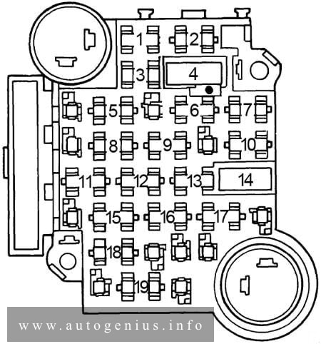
Fuse box diagram (high)
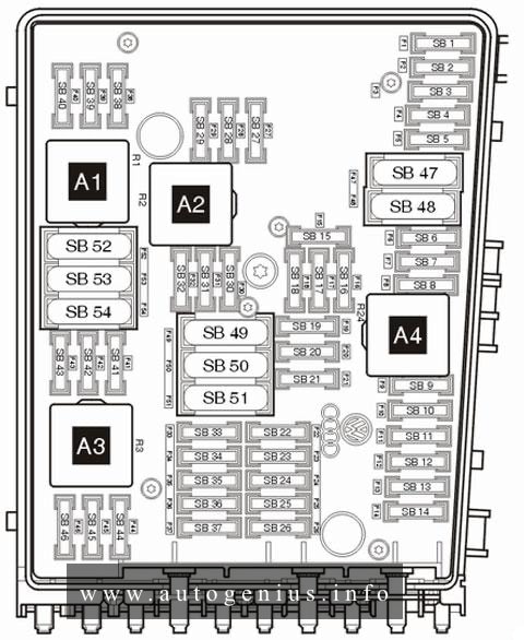
Assignment of the fuses and relays in the engine comparment (high)
| No. |
A |
Function/component |
| F1 | 30 | J104 – ABS with EDL control unit |
| F2 | 30 | J104 – ABS with EDL control unit |
| F3 | 20 | J393 – Convenience system central control unit V217 – Front passenger side wiper motor (from May 2005) Not assigned (from November 2005) |
| F4 | 5 | J519 – Onboard supply control unit |
| F5 | 20 | H2 – Treble tone horn (up to May 2005) H7 – Bass tone horn (up to May 2005) |
| 15 | J519 – Onboard supply control unit (horn) (from May 2005) | |
| F6 | 5 | N276 – Fuel pressure regulating valve (up to May 2005) |
| 15 | N276 – Fuel pressure regulating valve (from May 2005) J17 – Fuel pump (from May 2007) |
|
| 20 | N152 – Ignition transformer (up to May 2005) N… – Ignition coils 1-4 with output stage (up to May 2005) |
|
| F7 | 5 | F47 – Cruise control system brake pedal switch G476 – Clutch position sender Not assigned (from November 2005) |
| 40 | SF2 – Fuse 2 on fuse holder F (rear battery) (from May 2007) | |
| F8 | 10 | F265 – Map-controlled engine cooling system thermostat N205 – Inlet camshaft control valve 1 N80 – Activated charcoal filter solenoid valve 1 (pulsed) N18 – Exhaust gas recirculation valve N316 – Intake manifold flap air control valve V157 – Intake manifold flap motor N79 – Crankcase breather heater element N156 – Variable intake manifold changeover valve J293 – Radiator fan control unit Not assigned (from May 2005) |
| 15 | R190 – Digital radio satellite receiver (from May 2007) | |
| F9 | 10 | J583 – NOx sensor control unit (up to May 2005) J179 – Automatic glow period control unit (up to May 2005) J17 – Fuel pump relay (up to May 2005) N249 – Turbocharger air recirculation valve (from May 2005) N80 – Activated charcoal filter solenoid valve 1 (from May 2005) N75 – Charge pressure control solenoid valve (from May 2005) |
| F10 | 10 | G130 – Lambda probe after catalytic converter (up to May 2005) G131 – Lambda probe 2 after catalytic converter (up to May 2005) N18 – Exhaust gas recirculation valve (up to May 2005) N75 – Charge pressure control solenoid valve (up to May 2005) N345 – Exhaust gas recirculation cooler changeover valve (up to May 2005) J299 – Secondary air pump relay (up to May 2005) Not assigned (from May 2005) V144 – Fuel system diagnostic pump (USA/Canada) (from November 2005) G42 – Intake air temperature sender (from May 2007) G70 – Air mass meter (from May 2007) |
| F11 | 25 | J220 – Motronic control unit (up to May 2005) |
| 30 | J361 – Simos control unit (up to May 2005) J248 – Diesel direct injection system control unit (up to May 2005) |
|
| 10 | Z19 – Lambda probe heater (from May 2005) Z28 – Lambda probe 2 heater 2 (from May 2007) |
|
| F12 | 15 | G39 – Lambda probe (AXW, BAG, BCA, BKG, BLP, BLX and BLY) (up to May 2005) G108 – Lambda probe 2 (AXW, BLX and BLY) (up to May 2005) G130 – Lambda probe after catalytic converter (BCA) (up to May 2005) J583 – NOx sensor control unit (BAG, BKG and BLP) (up to May 2005) |
| 10 | Z29 – Lambda probe 1 heater after catalytic converter (from May 2005) Z30 – Lambda probe 2 heater after catalytic converter (from May 2007) |
|
| F13 | 15 | J217 – Automatic gearbox control unit (up to May 2005) J743 – Mechatronics for dual clutch gearbox |
| 30 | J743 – Mechatronic control unit (from May 2007) | |
| F14 | – | Not assigned |
| F15 | 40 | B – Starter (terminal 50) (up to May 2005) |
| 10 | V50 – Coolant circulation pump (from May 2005) | |
| F16 | 15 | J527 – Steering column electronics control unit (up to May 2005) |
| 5 | J104/J527 – Steering column control unit (from May 2005) | |
| F17 | 10 | J285 – Display control unit in dash panel insert (up to May 2005) |
| 5 | J285 – Control unit in dash panel insert (from May 2005) | |
| F18 | 30 | J608 – Special vehicle control unit (up to May 2005) R12 – Amplifier (from May 2005) J608 – Control unit for special vehicles (from May 2007) |
| F19 | 15 | R – Radio J503 – Control unit with display for radio and navigation system (up to May 2005) R19 – Digital satellite radio (from May 2007) |
| F20 | 10 | J412 – Mobile telephone operating electronics control unit (telephone /preparation for telephone) J503 – Control unit with display for radio navigation system (from May 2005) |
| 5 | J412 – Mobile telephone operating electronics control unit (from November 2005) | |
| F21 | – | Not assigned |
| F22 | – | Not assigned |
| F23 | 10 | Not assigned (up to May 2005) J623 – Engine control unit (from May 2005) J271 – Motronic current supply relay (100) (from May 2005) |
| 5 | J623 – Engine control unit (from November 2005) | |
| F24 | 10 | J533 – Data bus diagnostic interface (up to May 2005) |
| 5 | J533 – Data bus diagnostic interface (from May 2005) | |
| F25 | 40 | Not assigned (up to May 2007) J519 – Onboard supply control unit (A1) (from May 2007) |
| F26 | 10 | J220 – Motronic control unit (up to May 2005) Not assigned (from May 2005) |
| 5 | J248 – Diesel direct injection system control unit (up to May 2005) J317 – Terminal 30 voltage supply relay (up to May 2007) |
|
| 40 | J519 – Onboard supply control unit (D1) (from May 2007) | |
| F27 | 10 | N79 – Heater element for crankcase breather (up to May 2005) Not assigned (from May 2005) |
| F28 | 20 | J217 – Automatic gearbox control unit (up to May 2005) F125 – Multifunction switch (up to May 2005) |
| 25 | J623 – Engine control unit (from May 2005) | |
| F29 | 20 | N… – Ignition coils 1-4 with output stage (up to May 2005) N… – Injectors cylinders 1-4 (up to May 2005) |
| 5 | J496 – Additional coolant pump relay (from May 2005) J299 – Secondary air pump relay (from May 2005) |
|
| F30 | 20 | J162 – Heater control unit (up to May 2005) J485 – Auxiliary heater operation relay (from May 2005) |
| F31 | 25 | V – Windscreen wiper motor (up to May 2005) |
| 30 | V – Windscreen wiper motor (from May 2005) | |
| F32 | 10 | N… – Injectors (up to May 2005) Not assigned (from May 2005) |
| F33 | 15 | G6 – Fuel system pressurisation pump (up to May 2005) Not assigned (from May 2005) |
| F34 | – | Not assigned |
| F35 | – | Not assigned |
| F36 | – | Not assigned |
| F37 | – | Not assigned |
| F38 | 10 | V48 – Left headlight range control motor (up to May 2005) V49 – Right headlight range control motor (up to May 2005) J293 – Radiator fan control unit (from May 2005) N205 – Exhaust camshaft control valve 1 (from November 2005) N112 – Secondary air inlet valve (from May 2007) N321 – Exhaust flap 1 valve (from May 2007) N320 – Secondary air inlet valve 2 (from May 2007) V144 – Diagnosis pump for fuel system (from May 2007) N80 – Activated charcoal filter solenoid valve 1 (from May 2007) N156 – Secondary air inlet valve (from May 2007) N318 – Exhaust camshaft control valve 1 (from May 2007) |
| F39 | 5 | G226 – Oil level and oil temperature sender (up to November 2005) F – Brake light switch (up to November 2005) F47 – Brake pedal switch (from November 2005) G476 – Clutch position sender (from November 2005) |
| F40 | 20 | Dash panel fuse holder (SC1-SC6, SC7-SC11, SC29-SC31) (up to May 2005) N70 – Ignition coil 1 with output stage (from May 2005) N127 – Ignition coil 2 with output stage (from May 2005) N291 – Ignition coil 3 with output stage (from May 2005) N292 – Ignition coil 4 with output stage (from May 2005) |
| F41 | – | Not assigned |
| F42 | 10 | G70 – Air mass meter (AZV, BKC, BKD, BDK, BJB) J757 – Engine component current supply relay (from November 2005) |
| 5 | J49 – Electric fuel pump 2 relay (BGU, BCA) J271 – Motronic current supply relay (to November 2005) |
|
| F43 | 30 | Not assigned (up to May 2005) N70 – Ignition coil 1 with output stage (from May 2005) N127 – Ignition coil 2 with output stage (from May 2005) N291 – Ignition coil 3 with output stage (from May 2005) N292 – Ignition coil 4 with output stage (from May 2005) N323 – Ignition coil 5 with output stage (from May 2005) N324 – Ignition coil 6 with output stage (from May 2005) |
| F44 | – | Not assigned |
| F45 | – | Not assigned |
| F46 | – | Not assigned |
| F47 | 40 | J519 – Onboard supply control unit (up to November 2005) |
| 30 | J519 – Onboard supply control unit (D/1 left) (from November 2005) | |
| F48 | 40 | J519 – Onboard supply control unit (up to November 2005) |
| 30 | J519 – Onboard supply control unit (A/1 right) (from November 2005) | |
| F49 | 40 | Not assigned (up to May 2005) J681 – Terminal 15 voltage supply relay 2 (from May 2005) SF2 – Fuse in fuse holder F (rear battery) (from November 2005) J519 – Onboard supply control unit (L1) (from November 2005) |
| F50 | – | Not assigned |
| F51 | 50 | Q10 – Glow plug 1 (up to May 2005) Q11 – Glow plug 2 (up to May 2005) Q12 – Glow plug 3 (up to May 2005) Q13 – Glow plug 4 (up to May 2005) |
| 40 | J299/V101 – Secondary air pump relay (from May 2005) | |
| F52 | 50 | J519 – Onboard supply control unit SC40-SC42, SC46, SC47, SC49 (up to May 2005) |
| 40 | J59 – X-contact relief relay (from May 2005) | |
| F53 | 50 | Safety cutout for seat adjustment S44 – Seat adjustment thermal fuse 1, SB111 – Positive connection 1 (30a) (from November 2005) |
| F54 | 50 | J293 – Radiator fan control unit (up to May 2005) Not assigned (from May 2005) |
| Relay | ||
| A1 | Terminal 15 voltage supply relay -J329- (433) (up to May 2005) Motronic current supply relay -J271- (100) (up to November 2005) Engine components current supply relay -J757- (167) (from November 2005) |
|
| A2 | Terminal 50 voltage supply relay -J682- (433) (up to May 2005) Additional coolant pump relay -J496- (100) (from May 2005) |
|
| A3 | Current supply relay for engine components -J757- (167) (up to May 2005) Not assigned (from November 2005) |
|
| A4 | Terminal 30 voltage supply relay -J317- (458) (up to May 2005) Engine components current supply relay -J757- (167) (up to November 2005) Motronic current supply relay -J271- (100) (from May 2005) |
|
Assignment of the fuses and relays in the engine comparment
| No. |
A |
Function/component |
| 1 | 150 | C – Alternator (90A/120A) |
| 200 | C – Alternator (1401A) TV2 – Terminal 30 wiring junction (rear battery) |
|
| 2 | 80 | J500 – Power steering control unit V187 – Electromechanical power steering motor |
| 3 | 50 | J293 – Radiator fan control unit V7 – Radiator fan V177 – Radiator fan 2 (500 W) |
| 4 | 80 |
Not assigned (up to May 2005)
Fuses on fuse holder C, on left under dash panel: SC32-SC 37, Driver seat adjustment thermal fuse 1 – 30A (from May 2005)
Not assigned (from November 2005)
|
| 5 | 50 80 |
Fuses on fuse holder C, on left under dash panel SC12-SC17, SC19, SC22-SC27, SC32-SC38, SC43-SC45 (up to May 2005), (from May 2007)
|
| 100 | J604 – Auxiliary air heater control unit (from May 2005) Z35 – Auxiliary air heater element (from May 2005) |
|
| 50 | Fuses on fuse holder C, on left under dash panel SC12-SC17, SC19, SC22-SC27, SC32-SC38, SC43-SC45 (from November 2005) | |
| 6 | 125 |
SF1 – Fuse 1 on fuse holder F (rear battery) (up to May 2005), (from November 2005)
|
|
100
80
|
Fuses on fuse holder C, on left under dash panel: SC18-SC20, SC22-SC28, SC43-SC45 optional equipment (from May 2005) | |
| 7 | 50 |
Not assigned (up to May 2005), (from November 2005)
Fuses on fuse holder C, on left under dash panel: SC22-SC27 (from May 2005)
|
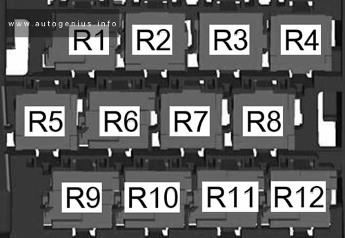
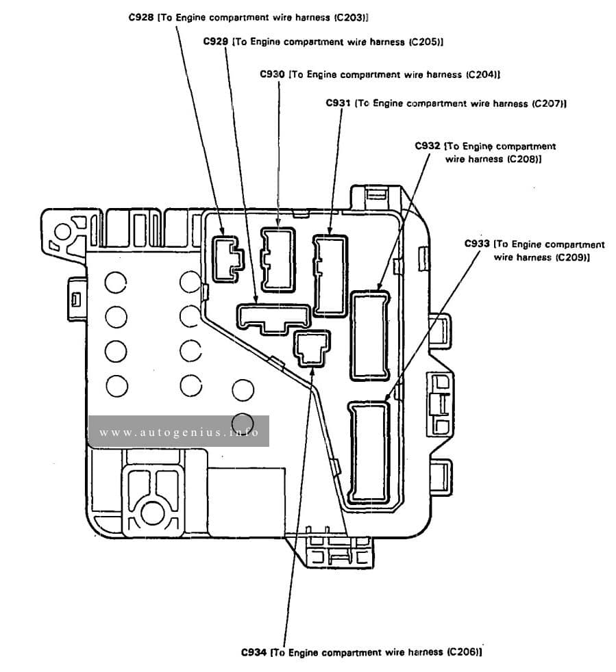
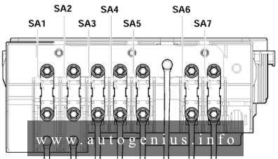
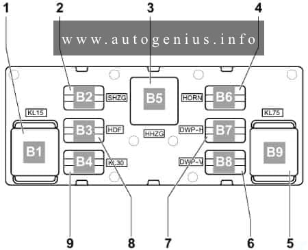
Relay carrier on onboard supply control unit (left under dash panel)
Fuse box diagram
Assignment of the fuses and relays in the instrument panel
| No. |
A |
Function/component |
| A | 30 | Seat adjustment thermal fuse 1 -S44- (from May 2004) |
| B | 30 | Seat adjustment thermal fuse 1 -S44- (up to April 2004) |
| Relay | ||
| 1 | Fresh air blower relay -J13- (53) (only with auxiliary heater) Low heat output relay -J359- (373) |
|
| 2 | Auxiliary heater operation relay -J485- (449) High heat output relay -J360- (370) Secondary air pump relay -J299- (100) |
|
| 3 | Headlight washer system relay -J39- (53) Terminal 50 voltage supply relay -J682- (449 / 53) |
|
| 4 | Additional coolant pump relay -J496- (449) (BLG) Fuel supply relay -J643- (449) (BCA) Fuel pump relay -J17- (449) Headlight washer system relay -J39- (53) |
|
| 5 | Terminal 50 voltage supply relay -J682- (433 / 53) Fuel pump relay -J17- (449) (J17- and -J485- are mini-relays and can be found on a relay slot) Auxiliary heater operation relay -J485- (449) (J17- and -J485- are mini-relays and can be found on a relay slot) |
|
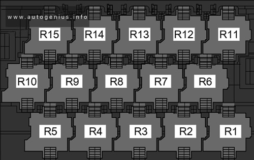
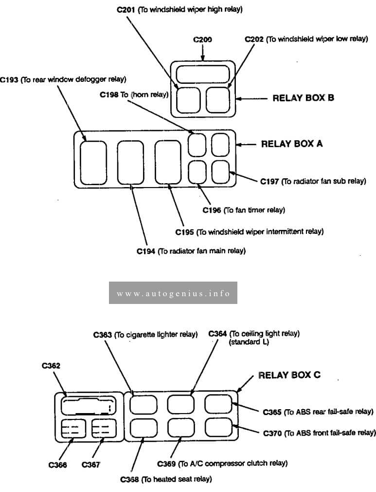
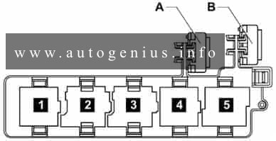
Relay assignment on relay carrier on onboard supply control unit
Fuse box diagram
Assignment of the fuses and relays
| No. |
Relay |
| 1 | Fresh air blower relay -J13- (up to May 2005) Terminal 15 voltage supply relay 2 -J681- |
| 2 | Heated exterior mirror relay -J99- (449) |
| 3 | Heated rear window relay -J9- (53) |
| 4 | Horn relay -J413- (449) |
| 5 | X-contact relief relay -J59- (460) |
| 6 | Double washer pump relay 2 -J730- (404) |
| 7 | Double washer pump relay 1 -J729- (404) |
| 8 | Not assigned |
| 9 | Terminal 30 voltage supply relay 2 -J689- (449) |
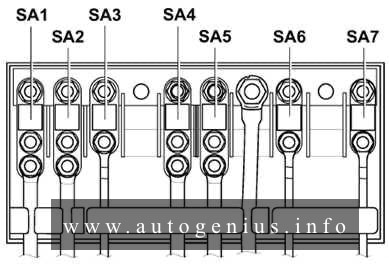
Additional relay carrier, under box on left in engine compartment
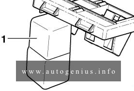
Assignment of the fuses and relays in engine compartment
| No. |
Relay |
| 1 | Automatic glow period control unit -J179- (461) / (457) |
WARNING: Terminal and harness assignments for individual connectors will vary depending on vehicle equipment level, model, and market.