Iveco Daily (IV; 2006 – 2011) – fuse and relay box diagram

Iveco Daily (IV; 2006 – 2011) – fuse and relay box diagram

Year of production: 2006, 2007, 2008, 2009, 2010, 2011


This article covers the second-generation  Iveco Daily IV (4th generation), produced from 2006 to 2011. It includes fuse box diagrams for the 2006, 2007, 2008, 2009, 2010 and 2011 models, provides details on the location of the fuse panels inside the vehicle, and explains the function and layout of each fuse.


Location

Iveco Daily(IV; 2006 - 2011) - fuse and relay box location
Iveco Daily(IV; 2006 – 2011) – fuse and relay box location


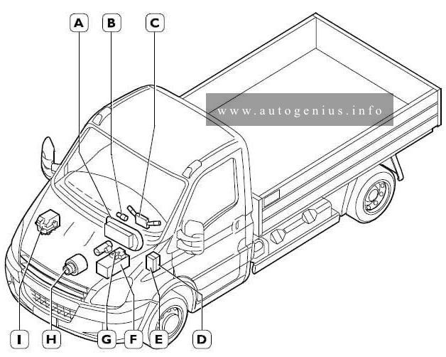
A. Instrument cluster
B. Key switch
C. Steering column switch unit
D. Interconnection central unit ”CPL”
E. Body Computer
F. Battery
G. Positive (+30) distribution central unit ”CBA”
H. Alternator
I. (Engine) interconnection central unit ”CVM”.
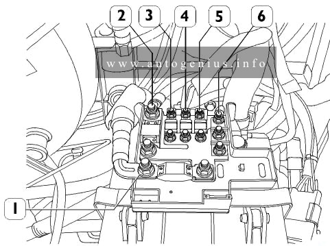
Engine compartment

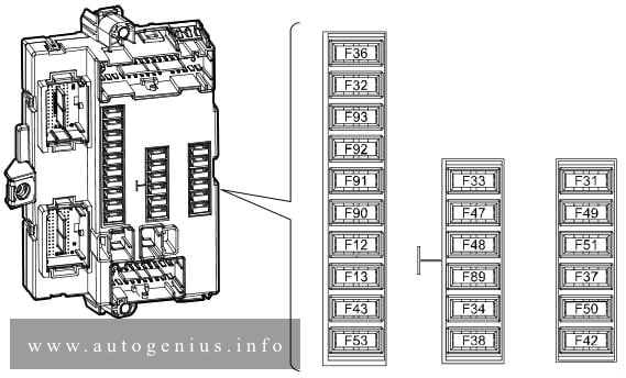
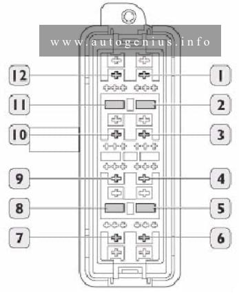
Fuse box diagram (Positive connection central unit – CBA)

Iveco Daily(IV; 2006 - 2011) - fuse and relay box doagram - engine compartment - positive cinnection central unit (CBA)
Iveco Daily(IV; 2006 – 2011) – fuse and relay box doagram – engine compartment – positive cinnection central unit (CBA)


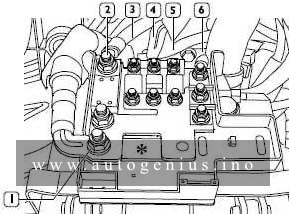
Assignment of the fuses in the engine compartment (positive cinnection central unit – CBA)


A
Function
1 500 Positive +30 for alternator starter
2 150 Positive for engine opening central unit ”CVM”
3 70 Positive +30 for ”CPL”
4 70 Positive +30 for ”CPL”
5 50 Positive +30 for box OPT
6 Positive +30 for ”CPL” – OPT prearrangement

Passenger compartment

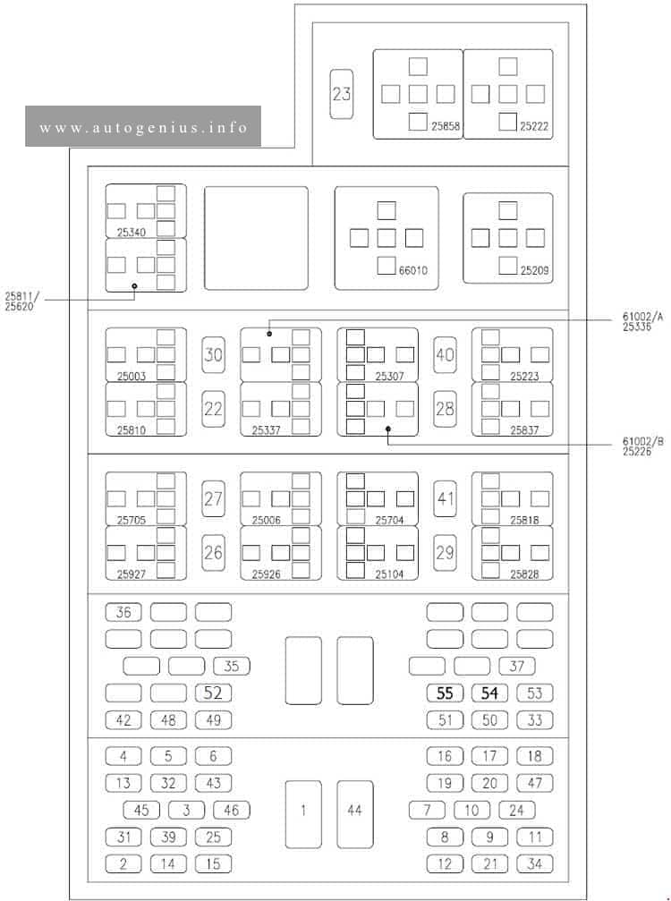
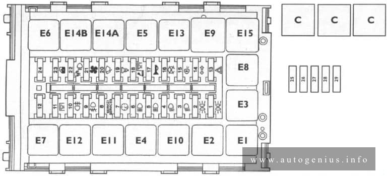
Fuse box diagram (Instrument panel interconnection central units – CPL)

Iveco Daily(IV; 2006 - 2011) - fuse and relay box doagram - passenger compartment - instrument panel interconnection central units (CPL)
Iveco Daily(IV; 2006 – 2011) – fuse and relay box doagram – passenger compartment – instrument panel interconnection central units (CPL)


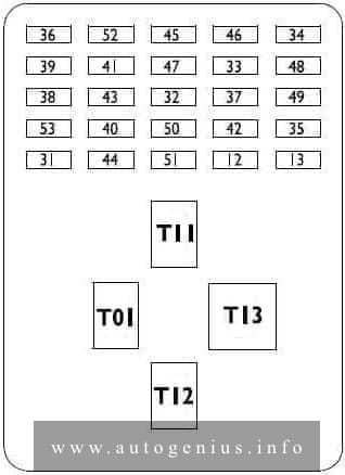
Assignment of the fuses in the passenger compartment (instrument panel interconnection central units – CPL)


A
Function
12 7.5 Right hand dipped headlight
13 7.5 Left hand dipped headlight – headlamp attitude rectifier
31 3 Relay T08-T17 in CVM and BC
32 15 Rotating-translating door
33 15 Air heater /Cigarette lighter
34 20 Socket
35 10 ABS8 or ESP8. Telma
36 20 Central locking
37 5 Switches for stop lights and various loads under 15
38 10 BC / Roof lamps internal relays power supply
39 15 Car radio – chrono-tachograph
40 10 Rh heated rear window
41 10 Lh heated rear window
42 5 Reverse lights switch
43 20 Windscreen wiper
44 AVAILABLE
45 AVAILABLE
46 AVAILABLE
47 25 Driver window winder
48 25 Passenger window winder
49 15 ECU for climate control system, car radio, heated seats
50 5 Airbag
51 5 Chrono-tachograph
52 AVAILABLE
53 7.5 Instrument cluster, rear fog lights
Relay
T-01 Right and left hand dipped headlights
T-11 Heated rear window
T-12 Cigarette lighter / socket / heater or climate control system
T-13 Power release from key

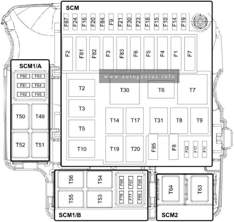
Fuse box diagram (Interconnection central unit – CVM)

Iveco Daily(IV; 2006 - 2011) - fuse and relay box doagram - Interconnection central unit (CVM)
Iveco Daily(IV; 2006 – 2011) – fuse and relay box doagram – Interconnection central unit (CVM)


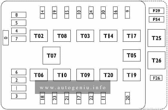
Assignment of the fuses in the interconnection central units – CVM)


A
Function
0 60 Ignition glow plugs
1 40 ABS8 or ESP8
2 30 ABS8 or ESP8
3 30 ECU ESV1 (automatic gearbox)
4 30 ECU ESV1 (automatic gearbox)
5 30 Start-up switch
6 20 Heated mirrors and windscreen
7 20 Side marker lamps
8 30 Heater or climate control system fans
9 20 Windscreen washer
10 7.5 Horn
11 10 EDC16 (secondary loads)
14 7.5 Right hand full beam headlight
15 7.5 Left hand full beam headlight
16 5 EDC16, T02, T14, Additional heater
17 15 EDC16 (primary loads)
18 10 ECU ESV1 (automatic gearbox)
19 5 Baruffaldi
20 25 Fuel filter heater
21 15 Fuel pump
22 25 EDC16 (primary loads)
23 10 Additional heater
24 15 ECU ESV1 (automatic gearbox), PTO
26 10 Trailer socket
29 40 Air spring suspensions
30 15 Left and right hand front fog lights
54 40 Air spring suspensions
T02 20 Right and left hand full beam headlights
T03 20 Horn
T05 20 Baruffaldi power supply
T06 20 Heater / mirrors / windscreen
T07 20 Side marker lamps
T08 20 Heater or climate control system fans
T09 20 EDC16 (main relay)
T10 20 Fuel pump
T14 20 Left and right hand front fog lights
T17 20 Windscreen washer
T19 20 Fuel filter heater
T20 20 Diagnosis MODUS
T25 10/20 Windscreen wiper on/off
T26 10/20 Windscreen wiper 1st / 2nd speed
(F26, F29, F54, T25, T26) in container, out of central unit

Engine Compartment

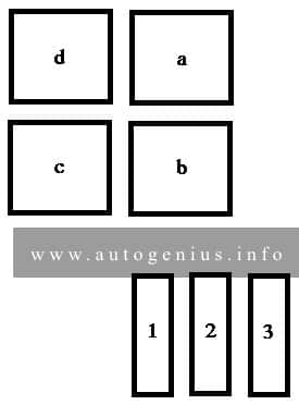
Fuse box diagram (Optional fuse box)

Iveco Daily(IV; 2006 - 2011) - fuse and relay box doagram - engine compartment - optional fuse box
Iveco Daily(IV; 2006 – 2011) – fuse and relay box doagram – engine compartment – optional fuse box


Assignment of the fuses in the engine compartment (optional fuse box)

No. Function A
F-55 (2) Rotary lights 10
F-25 (5) Trailer connector 10
F-28 (8) APU power supply 15
F-27 (11) Working lights 10
Relays
T04 (1) Rotary lights 20
T16 (12) Working lights 10
T15 (3) Free
T22 (4) Air conditioning compressor actuation 20
T18 (6) Baruffali cut-out 20
T24 (7) Power takeoff actuation enable 20
T23 (9) Air conditioning compressor 20
T21 (10) Compressor ON signal fro EDC 16 20
WARNING: Terminal and harness assignments for individual connectors will vary depending on vehicle equipment level, model, and market.

Iveco Daily (III; 2000 – 2006) – fuse and relay box diagram

Iveco Daily (III; 2000 – 2006) – fuse and relay box diagram


Year of production: 2000, 2001, 2002, 2003, 2004, 2005, 2006


This article covers the second-generation Iveco Daily (III), produced from 2000 to 2006. It includes fuse box diagrams for the 2000, 2001, 2002, 2003, 2004, 2005 and 2006 models, provides details on the location of the fuse panels inside the vehicle, and explains the function and layout of each fuse.

Passenger compartment

Fuse box diagram

Iveco Daily(III; 2000 - 2006) - fuse and relay box diagram - passenger compartment
Iveco Daily(III; 2000 – 2006) – fuse and relay box diagram – passenger compartment


Assignment of the fuses in the passenger compartment

No Function A
1 ID/TCA (.11): Thermal starter 40
1 UNIJET (.13-.15): Thermal starter 80
1 UNIJET F1A (.10-.12): Thermal starter, additional heater 30
2 Immobilizer/Warming/EDC 5
3 DDS device 5
4 Instrument cluster (+30) 5
5 Instrument cluster (+15) 5
6 Stalk unit (rear fog guard, flasher) 5
7 Stalk unit (low beams) 10
8 Stalk unit (high beams) 15
9 Stalk unit (side lights) 15
10 Windscreen wiper 15
11 Stalk unit (direction indicators/hazard warning lights) 15
12 Stalk unit (horns) 15
13 Reversing light 5
14 Side light, clearance, no. plate light 5
15 Side light cluster lighting 5
16 Left low beam headlamp 10
17 Right low beam headlamp 10
18 Left high beam headlamp 10
19 Right high beam headlamp/headlamp aming 10
20 Interior lighting/radio/cigar lighter 10
20 UNIJET F1A (.10-.12): Interior lighting/radio 10
21 Electric windscreen defrosting unit 30
21 UNIJET F1A (.10-.12): Cigar lighter 15
22 Heated fuel filter 15
23 EDC electronic control unit 25
24 EDC 10
25 Stop lights 5
26 13-pin current socket 15
27 13-pin current socket 15
28 13-pin current socket 10
29 38-pin diagnostic connector 5
30 Fog lamps 10
31 Climate control, additional heater, engine cooling 5
31 UNIJET F1A (.10-.12): Compressor, timer, engine fan 10
32 Climate control 5
33 Additional heater 20
34 Headlamp washer 20
35 Rear differential lock 5
36 ABS, EBD, ABD failure warning light 5
37 ABS 5
39 Heated mirrors 10
39 UNIJET F1A (.10-.12): Heated mirrors, heated rear-screen, heated windscreen 10
40 Power windows 30
40 UNIJET F1A (.10-.12): Power windows (left) 20
41 Heated rear-screen, heated windscreen 10/ 20
42 Self-levelling suspensions (Wabco) 5
43 Air bag failure warning light 5
44 Self-levelling suspensions (Wabco) 40
45 Air-bag 5
46 Solenoid valve for thermal starter 5
46 UNIJET F1A (.10-.12): Power windows (right) 20
47 Electric fuel pump 10
48 Door locking/alarm 30
49 Door locking/alarm 5
50 Rear differential lock 30
51 Total power takeoff 10
52 Front differential lock (4×4) 30
53 Self-levelling suspensions Techniek) 30
54 Electric hatch (van and 6+1) 15
55 Rototranslating door 15
Code Relays
25035 Switching on external lights
25003 Switching on fog lamps
25006 Switching on stop lights
25704 Total power takeoff engagement control
25104 Switching off Retarder with ABS on
25209 Loads cut-off during starting
25222 Thermal starter engagement enable
25223 Thermal starter fan control
25307 Climate control compressor engagement
25336 Engine cooling
25337 Climate control compressor disengagement
25340 Compressor on signal
25620 Fuel filter clogged signal
25705 Diagnostics enable
25810 Heated fuel filter circuit control
25811 Advance variator control (KSB)
25818 Heated windscreen switching on
25837 Electric fuel pump switching on
25858 EDC switching on
25926 Suspension raising enable
25927 Suspension lowering enable
25928 Rear-screen heating switching on
61002A Anti-retum from Trinary
61002В Anti-retum from TGC (bus)
66010 Timer for headlamp washer
WARNING: Terminal and harness assignments for individual connectors will vary depending on vehicle equipment level, model, and market.

Iveco Daily (V; 2011 – 2014) – fuse and relay box diagram

Iveco Daily (V; 2011 – 2014) – fuse and relay box diagram

Year of production: 2011, 2012, 2013, 2014


This article covers the second-generation  Iveco Daily V (5th generation), produced from 2011 to 2014. It includes fuse box diagrams for the 2011, 2012, 2013 and 2014 models, provides details on the location of the fuse panels inside the vehicle, and explains the function and layout of each fuse.

Passenger compartment (under the dashboard)

Fuse box diagram

Iveco Daily (V; 2011 - 2014) - fuse and relay box doagram - passenger compartment
Iveco Daily (V; 2011 – 2014) – fuse and relay box doagram – passenger compartment


Assignment of the fuses in the passenger compartment (under the dashboard)

No Function A
F12 Т1b relay (30-87) for right low beam headlight 7,5
F13 T1a relay (30-87) for left low beam headlight – headlight adjuster 7,5
F31 T54 relay (86) for headlight washers and T50 – T51 – T52 – T53 – eln motors and controls for electric windows 5
F32 T44 relay (30-86) for battery removal with minimum voltage – internal lighting 7,5
F33 Ooutswinging door 15
F34 Fitter socket 20
F36 T20 relay for MODUS car radio – tachograph – convergence – siren – parking sensor 15
F37 Instrument panel – stop lights – trailer socket 7,5
F38 Central locking 20
F42 ABS9 or ESP9 5
F43 T23a relay (86-87) for windscreen washer and T23b relay (86-87) 20
F47 T25a relay (86-87) and T25b (86-87) for driver’s side electric window 25
F48 T26a relay (86-87) and T26b (86-87) for passenger side electric window 25
F49 Control panel – tachograph – exp. module – fitter socket – ASR control – Telma (coil) – video camera – outswinging – rear differential lock 5
F50 Airbag 5
F51 Green filter – car radio – toe-in – parking sensors -CAF 5
F53 Instrument panel – timer for supplementary heater 5
F89 AVAILABLE
F90 T11a relay (30-86) for left full beam headlight 7,5
F91 T11b relay (30-86) for right high beam headlight 7,5
F92 T12a relay (30-86) for left foglight 7,5
F93 T12b relay (30-86) for right foglight 7,5
No. Relays
T01а Left low beam headlight – headlight adjuster
T01b Right low beam headlight
Т11а Left high beam headlight
T11b Right high beam headlight
Т12а Left foglight
Т12b Right foglight
Т23а Windscreen washer
Т25а Driver’s side electric window UP
Т25b Driver’s side electric window DOWN
Т26а Passenger side electric window UP
Т26b Passenger side electric window DOWN
Т37а Rear doors central closing
Т37b Central closing (common)
Т37с Side doors central closing
T37d Rear door central closing
Т44 Battery removal with minimum voltage

Engine compartment (Fuse box above the battery)

Fuse box diagram

Iveco Daily (V; 2011 - 2014) - fuse and relay box doagram - engine compartment (above the battery)
Iveco Daily (V; 2011 – 2014) – fuse and relay box doagram – engine compartment (above the battery)


Assignment of the fuses in the engine compartment (above the battery)

No Function A
1 +30 positive from F75 for starter motor, alternator and retarder (if present) 500
2 +30 positive from F70 for SCM BUS-BAR 150
3 +30 positive from F73 for pre-heating glow plugs 60
4 +30 positive from F72 for braking node 40
5 +30 positive from F7I for Ist Body Computer power 80
6 +30 positive to F64 in SCM/A for IBS sensor for Stop & Start

Engine compartment

Fuse box diagram

Iveco Daily (V; 2011 - 2014) - fuse and relay box doagram - engine compartment
Iveco Daily (V; 2011 – 2014) – fuse and relay box doagram – engine compartment


Assignment of the fuses in the engine compartment

No Function A
F01 Air suspensions 40
F02 Ignition switch 30
F03 Cab climate control fans and engine coolant supplementary heater 40
F04 Braking system (valves) 30
F05 Air suspensions 40
F06 SCM 1 /А – SCM 1 /В – SCM2 power supply 40
F07 T7 relay (30-87) for power discharge from ignition switch 40
F08 T8 relay (30-87) for fuel pump 15
F09 Automatic transmission 30
F11 T64 relay (30-87) for heated exterior mirrors and heated windscreen 15
F11 EDC FI A (primary loads) from MAIN RELAY injectors (CNG) 15
F14 Automatic transmission – MAIN RELAY T9 (86) 10
F15 T2 relay (30-87) for BOSCH cooling pump 10
F16 Cigarette lighter from T7 15
F17 EDC FIC (secondary loads) from MAIN RELAY Smart Drive Unit (CNG) 10/15
F18 Rear differential lock 30
F19 T6 relay (30-87) for horn 7,5
F20 13 pin socket 10
F21 TI4 relay (30) for cylinder solenoid valves (CNG) 7,5
F22 EDC F1A and F1C (primary loads) from MAIN RELAY – lambda probe 20
F22 Waste gate (CNG) – lambda probes (CNG) 15
F23 T19 relay (30-87) for wipers 30
F24 Power socket from T7 15
F30 T3 relay (30-87) for side marker lamps 7,5
F81 Automatic transmission 30
F82 Body computer 2nd power 70
F83 T30 relay (30-87) for heating fans inside cab 40
F84 Solenoid valve power for the cylinders 15
F84 T5 and T14 relays for Baruffaldi coupling 7,5
F85 T31 relay (30-87) for fuel filter and sediment filter heater 25
F87 EDC – automatic transmission 7,5
F87 5SF – automatic transmission 7,5
Relay
T02 BOSCH cooling pump 20
T02 Baruffaldi coupling from trinary (CNG) 20
Т03 Side marker lamps 30
T05 Ist gear Baruffaldi coupling 30
T06 Horn 20
T07 Power discharge from ignition switch 50
T08 Fuel pump 20
T09 MAIN RELAY 30
T10 Engine start-up prevention 30
T14 2nd gear Baruffaldi coupling 20
T14 Cylinder solenoid valves (CNG) 20
T17 Windscreen wiper 1or 2nd speed 10/20
T19 Indscreen wiper speed activation 10/20
T20 Diagnostics with MODUS 20
Т30 Cab heating fans 50
T31 Fuel filter heater and sediment filter 30
SCM1/A
F60 Supplementary climate control 30
F61 T51 relay (30-87) for air conditioner compressor 7,5
F62 T52 relay (30-87) for right heated rear window 10
F63 Left heated rear window blow-by – unit heater – T56 relay (86) for compressor 10
F64 IBS sensor for Stop & Start 5
F65 T7 relay (30-87) for heated seats 20
Relay
T49 Stop & start 30
T50 AVAILABLE
T51 Compressor activation from climate control 20
T52 Heated rear windows 20
SCM1/B
F66 T54 relay (30-87) for headlight washers 15
F67 AVAILABLE
F68 AVAILABLE
F69 Optional 4448 for bus 5
F77 AVAILABLE
F78 AVAILABLE  –
Relay
T53 Unit heater 20
T54 Headlight washers 20
T55 Power Take Off 10/20
T56 Stop lights with TELMA retarder activated 10/20
SCM2
T63 AVAILABLE
T64 External heated mirrors – heated windscreen 20

WARNING: Terminal and harness assignments for individual connectors will vary depending on vehicle equipment level, model, and market.

Iveco Daily (II; 1989 – 2000) – fuse and relay box diagram

Iveco Daily (1989 – 2000) – fuse and relay  box diagram

Year of production: 1989, 1990, 1991, 1992, 1993, 1994, 1995, 1996, 1997, 1998, 1999, 2000


This article covers the second-generation   Iveco Daily II (2nd generation), produced from 1989 to 2000. It includes fuse box diagrams for the 1989, 1990, 1991, 1992, 1993, 1994, 1995, 1996, 1997, 1998, 1999 and 2000 models, provides details on the location of the fuse panels inside the vehicle, and explains the function and layout of each fuse.

Fuse box diagram

Iveco Daily (II; 1989 - 2000) - fuse and relay box doagram
Iveco Daily (II; 1989 – 2000) – fuse and relay box doagram


Assignment of the fuses in the fuse box

No. A Function
1 5 Lh front parking light – Lh number plate light- Rh rear parking light – Rh front and Lh rear marker
2 5 lights – Dashboard. Rh front parking light – Rh number plate light -Lh rear parking light – Lh front and Rh rear
3 7,5 marker lights. Lh low beam light
4 7,5 Rh low beam light
5 7,5 Lh high beam light
6 7,5 Rh high beam light
7 3 Electronic speedometer or tachograph
8 5 Brake – instrument – telltale failure
9 10 Fog headlights
10 3 Rear fog lamps
11 5 Interior lighting (bus)
12 7,5 Not used
13 10 Hazard lights
И 5 Tractor unit turn signal lights
15 3 Engine stop
16 7,5 Reversing lights – stop lights
17 10 Homs
18 7,5 Interior lighting – Cigar lighter
19 15 Heated fuel oil filter
20 10 Windscreen wiper – Windscreen washer pump
21 15 Electric heater – Electromagnetic fan
22 7,5 Push switch lighting – flashing light
23 25 Power window – Electromagnetic fan
24 10 Emergency control pushbutton (Bus)
25 20 Air conditioning
26 20 Air conditioning
27 25 Air conditioning
28 25 Electric heater
29 40 Thermostarter control unit
Relays
E1 Low beam lights (switch contacts)
E2 High beam lights (N.O. contact)
E3 Users cutoff during starting stage (N.O. contact)
E4 Fog lamps (switch contacts)
E5 Heated fuel oil filter
E6 Emergency control unit
E7 Day lights + fog lamps
E8 Horns (N.O. contact)
E9 Windscreen wiper intermittent
E10 Flashing light (N.O. contact)
E11 Diode for emergency control unit (with day lights)
E12 Not used
E13 Brake system failure (switch contact)
E14a Emergency control unit (with day lights)
E14b Emergency control unit (with day lights)
E15 Direction indicators – single charge emergency
C Air conditioning

Engine compartment

Fuse box diagram

Iveco Daily (II; 1989 - 2000) - fuse and relay box diagram - engine compartment
Iveco Daily (II; 1989 – 2000) – fuse and relay box diagram – engine compartment


Assignment of the fuses in the engine compartment

Fuse Ampere rating [A] Description
1 30 Electro-hidraulic assembly (Power Pack)
2 20 Electronic control unit (from battery positive)
3 20 Electronic control unit (lock and key protection)


Relay Description
a Circuit protection diode casing
b Optical indicator ON button
c Reversing light
d Buzzer (acoustic indicator)

WARNING: Terminal and harness assignments for individual connectors will vary depending on vehicle equipment level, model, and market.