Jeep Grand Wagoneer (2022 – 2024) – fuse and relay box diagram
Year of production: 2022, 2023, 2024
This article covers the fourth-generation Jeep Wagoneer (WS), available from 2021 to the present. It includes fuse box diagrams for the 2022, 2023 and 2024 Jeep Wagoneer models, provides information on the locations of the fuse panels within the vehicle, and details the assignment of each fuse (fuse layout).
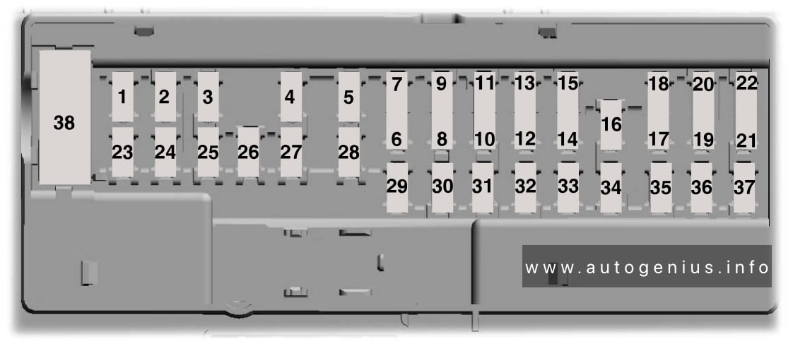
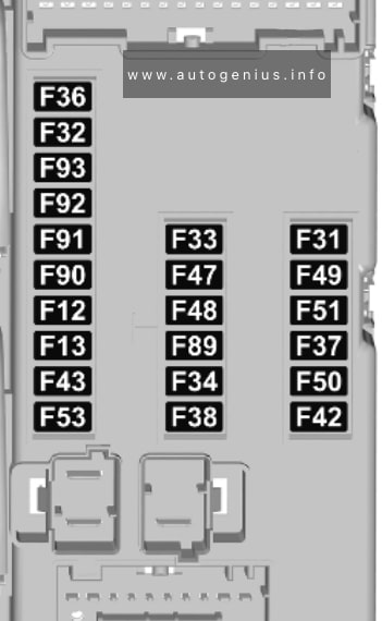
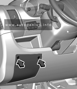
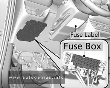
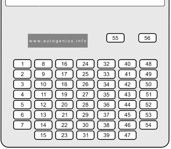
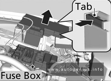
Pasenger Compartment Fuse Box
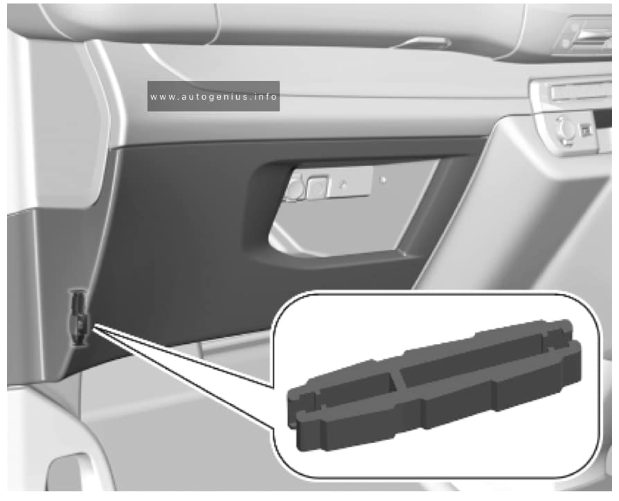
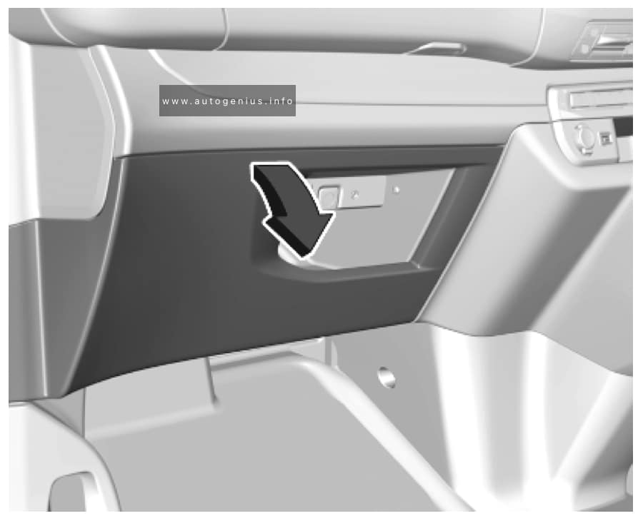
Fuse box location
The Interior Power Distribution Center is located under the driver’s instrument panel.

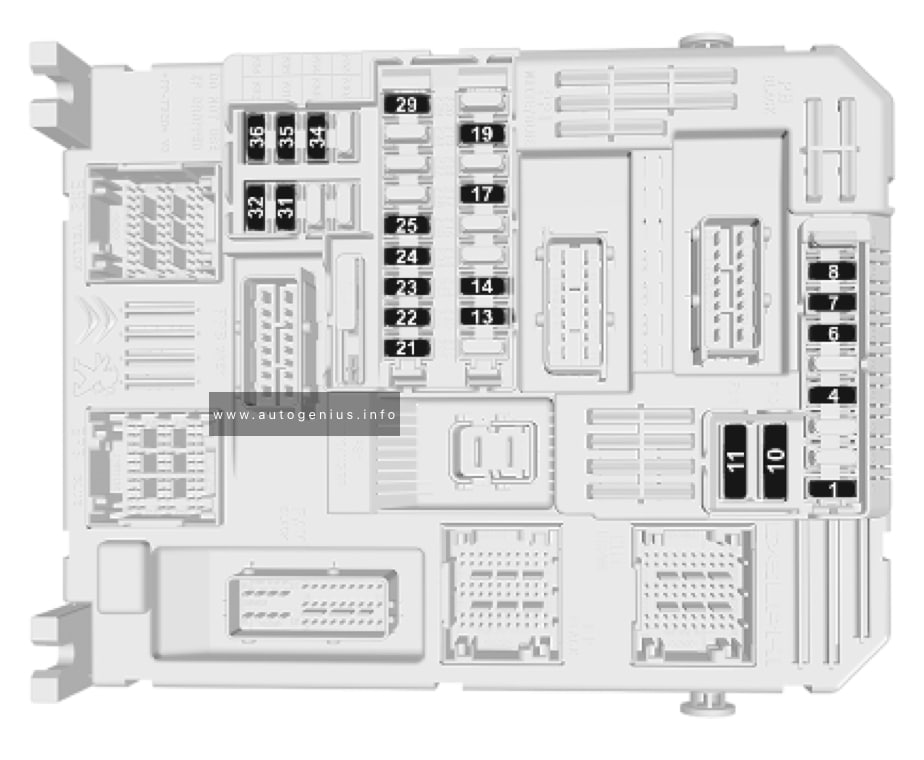
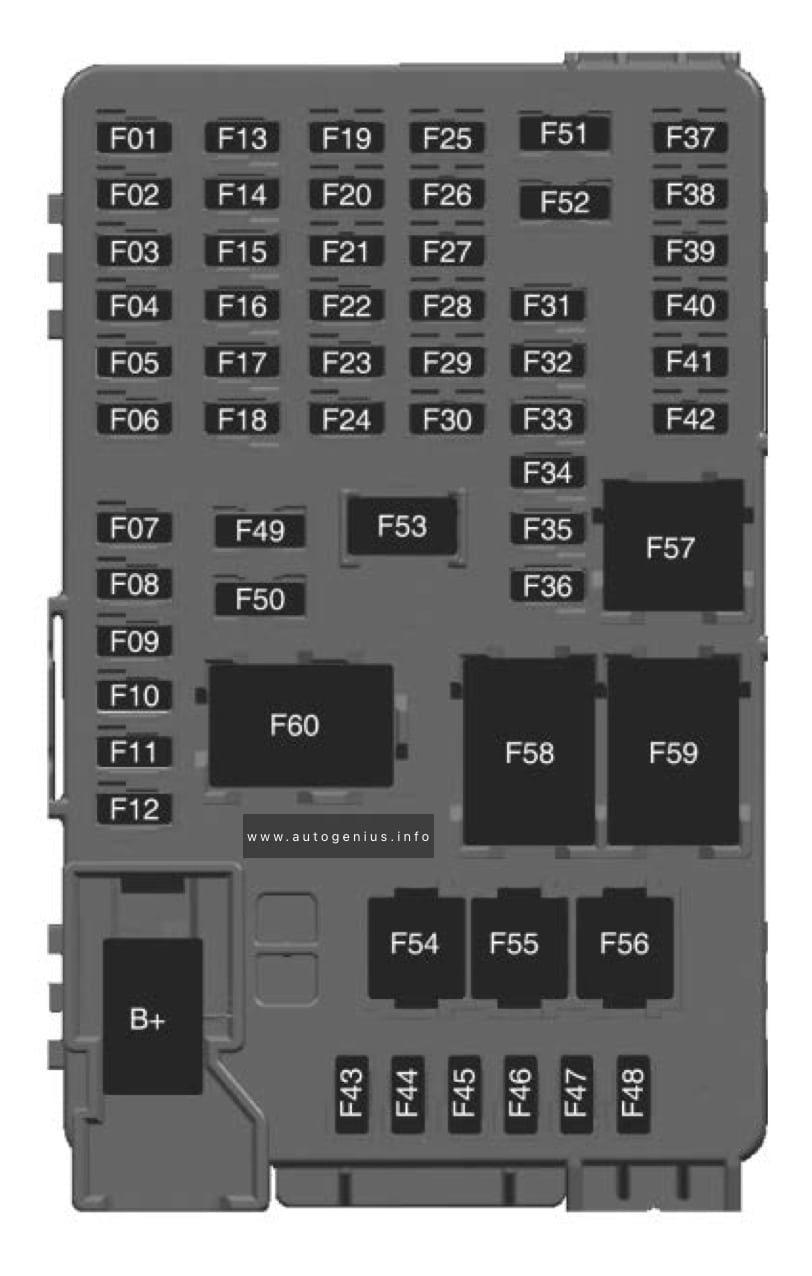
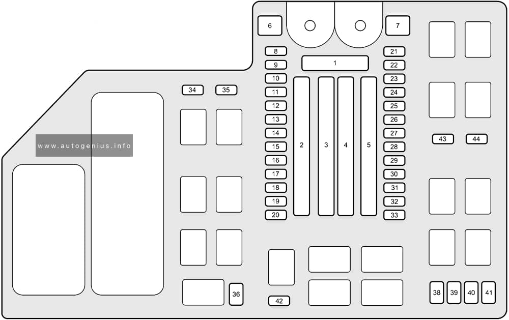
Fuse box diagram
Assignment of the fuses in the Interior Power Distribution Center
| № | Cartridge Fuse | Micro Fuse | Description |
|---|---|---|---|
| F01 | – | – | Spare |
| F02 | – | – | Spare |
| F03 | – | 15A Blue | MOD Seat Heater Frt (Steering Wheel) |
| F04 | – | 10A Red | Night Vision Module / Driver Monitoring Camera (DMC) |
| F05 | – | – | Spare |
| F06 | – | – | Spare |
| F07 | – | – | Spare |
| F08 | – | 10A Red | Automatic Gearbox Shifter Module (AGSM) / Steering Column Lock / HUD |
| F09 | – | – | Spare |
| F10 | 40A Green | – | HVAC Blower Motor |
| F11 | – | – | Spare |
| F12 | – | 20A Yellow | Assy Cigar Lighter |
| F13 | – | 10A Red | Assy Mirror Inside Rearview / Sunroof Single – Dual Pane / Port UC1 Dual USB RR / Interior Monitoring Camera |
| F14 | – | 10A Red | Refrigerator Box / In Vehicle Safe |
| F15A | – | – | Spare |
| F15B | – | – | Spare |
| F16 | – | 10A Red | MOD ORC |
| F17 | – | – | Spare |
| F18 | – | – | Spare |
| F19 | – | – | Spare |
| F20 | – | 10A Red | Overhead Console Assy (OHC) W/Sunshade / Intrusion Module |
| F21 | 30A Pink | – | Trailer Tow Electric Brake – Aftermarket |
| F22 | – | – | Spare |
| F23 | – | – | Spare |
| F24 | – | – | Spare |
| F25 | – | – | Spare |
| F26 | – | – | Spare |
| F27 | – | – | Spare |
| F28 | – | – | Spare |
| F29 | – | – | Spare |
| F30 | – | – | Spare |
| F31 | – | – | Spare |
| F32 | – | 10A Red | MOD ICS Switch Bank / SW Bank Upper/ SW EPB / Aux Switch Bank Module (ASBM)/ Mod HVAC Cntrl Frt/ Humidity Rain Light Sensor (HRLS) |
| F33 | – | 15A Blue | Transfer case SW / SW Bank Lower / Mod ICS Switch Bank Rear / Climate Control Display / Suspension SW |
| F34 | – | – | Spare |
| F35 | – | 10A Red | IRCAM Heater |
| F36 | – | – | Spare |
| F37 | – | – | Spare |
| F38 | – | – | Spare |
| F39 | – | – | Spare |
| F40 | – | – | Spare |
| F41A | – | – | Spare |
| F41B | – | – | Spare |
| F42A | – | – | Spare |
| F42B | – | 10A Red | MOD HVAC Control Frt |
| F43A | – | – | Spare |
| F43B | – | – | Spare |
| F44 | – | 15A Blue | MOD Cluster CCN / MOD SGW (Cybersecurity) |
| F45 | 30A Pink | – | MOD Inverter 150W |
| F46 | – | – | Spare |
| F47A | – | – | Spare |
| F47B | – | – | Spare |
| F48A | – | – | Spare |
| F48B | – | – | Spare |
| F49 | – | 7.5A Brown | MOD RF HUB/ Module Ignition (MD KIN) |
| F50A | – | 10A Red | Port UCI Dual USB Rear |
| F50B | – | 10A Red | Port Diagnostics 1 & 2 |
| F51A | – | – | Spare |
| F51B | – | – | Spare |
| F52 | – | – | Spare |
| F53 | – | 20A Yellow | MOD CMCM (Radio) |
| F54A | – | – | Spare |
| F54B | – | – | Spare |
| F55 | – | – | Spare |
| F56 | – | – | Spare |
| F57 | – | – | Spare |
| F58 | – | – | Spare |
| F59 | – | – | Spare |
| F60 | – | – | Spare |
| F61 | – | – | Spare |
| F62A | – | – | Spare |
| F62B | – | – | Spare |
| F63A | – | 15A Blue | Port UC1 Dual USB Frt / Wireless Charging Pad MOD (WCPM) – High/Premium Only |
| F63B | – | 15A Blue | Telematics Box Module (TBM)/ Mod-DCSD/Mod FPDM |
| F64A | – | 10A Red | MODORC |
| F64B | – | 10A Red | Steering Column Control Module (SCCM) |
| F65 | – | 5A Tan | MOD SGW (Cybersecurity) |
| F66 | – | – | Spare |
| CB1-CB6 | – | – | Spare |
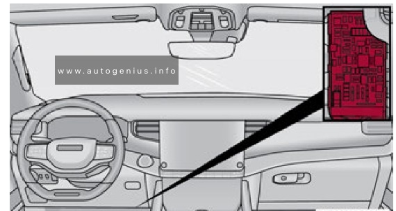
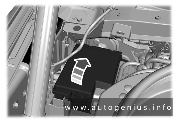
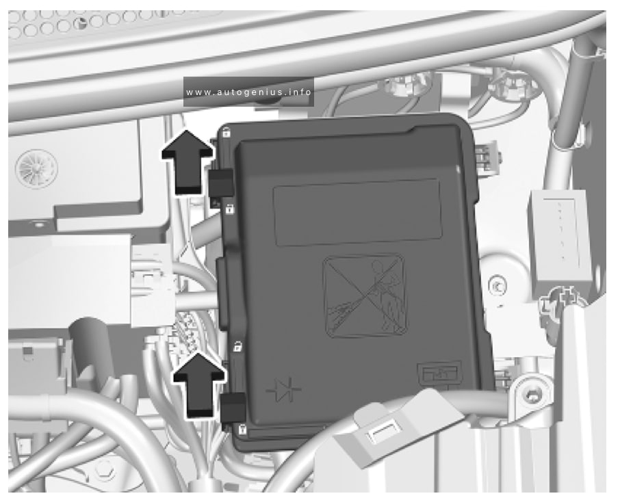
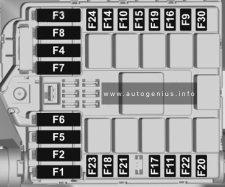
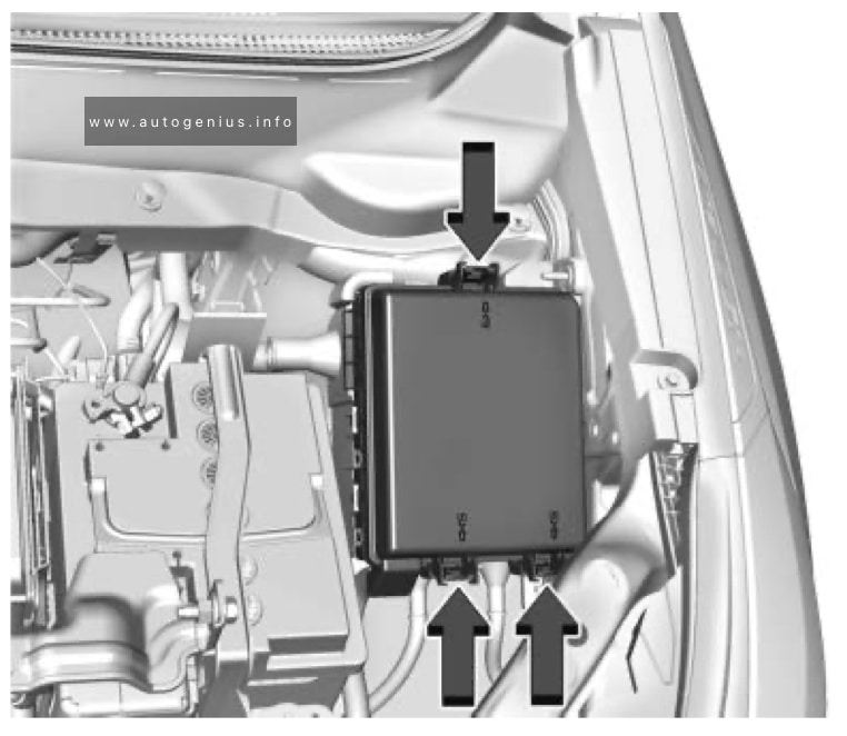
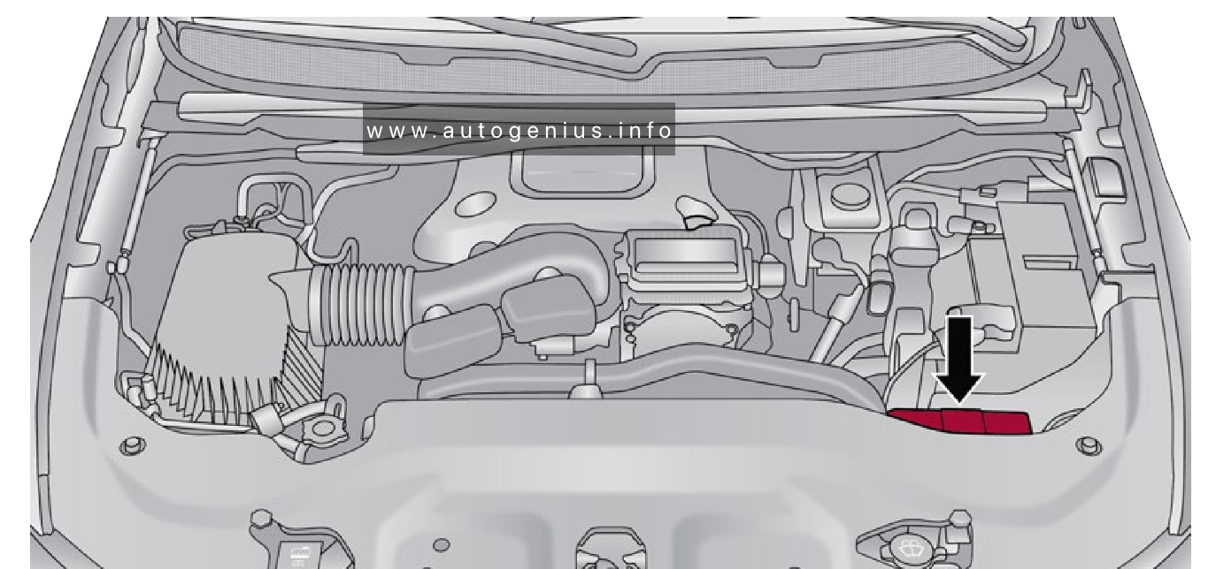
Engine Compartment Fuse Box
Fuse box location
The Power Distribution Center (PDC) is located on the driver’s side of the engine compartment, behind the headlamp.
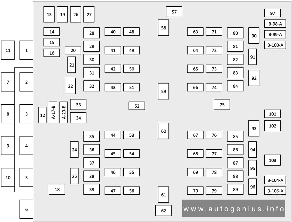
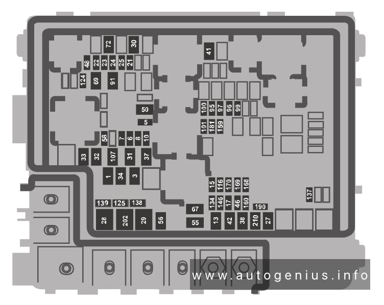
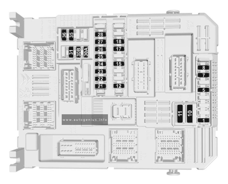
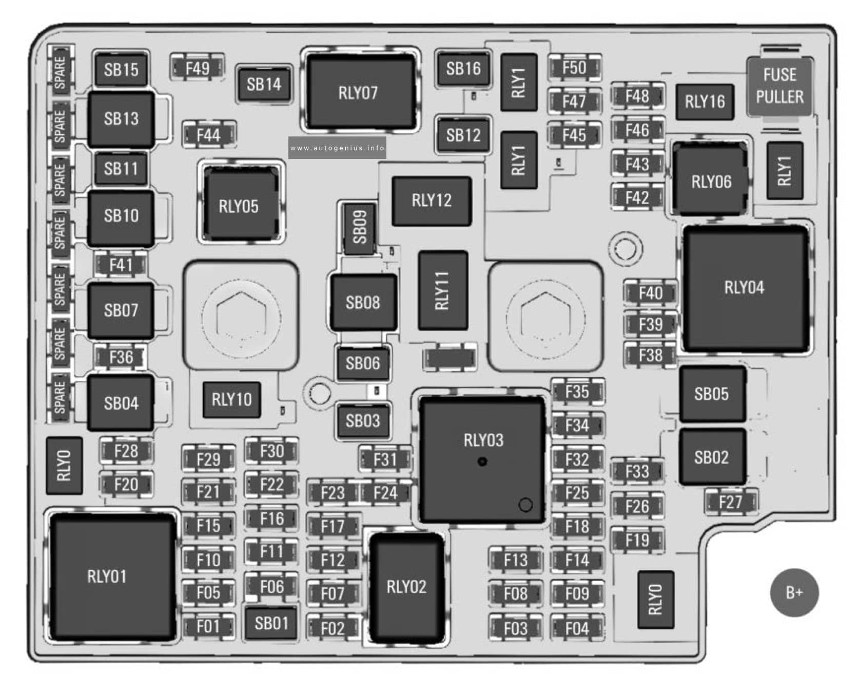
Fuse box diagram

Assignment of the fuses in the Power Distribution Center (PDC)
| № | Cartridge Fuse | Micro Fuse | Description |
|---|---|---|---|
| F01 | – | – | Crank Batt |
| F02 | 80A Gray | – | Elec Pwr Str #1 |
| F03 | 500A Gray | – | Starter |
| F04 | 250A Gray | – | Alternator |
| F05 | 80A Gray | – | Elec Pwr Str #2 |
| F06 | Shunt | – | Aux Battery |
| F07 | 100A Gray | – | Rad Fan |
| F08 | – | – | Spare |
| F09 | 80A Gray | – | IPDC |
| F10 | 150A Gray | – | RPDC |
| F11 | 150A Gray | – | PCR |
| F12 | – | – | Spare |
| F13 | 40A Green | – | Starter |
| F14 | – | 10A Red | GNMM / VPMS |
| F15 | – | 10A Red | ECM |
| F16 | – | 15A Blue | Cluster |
| F17A | – | 10A Red | EPS |
| F17B | – | 10A Red | ATMM |
| F18 | – | – | Spare |
| F19 | 30A Pink | – | BSM #2 Valves |
| F20 | – | – | Spare |
| F21 | – | – | Spare |
| F22 | – | – | Spare |
| F23A | – | 10A Red | ECM / PPU / MGU / BSM / SLM |
| F23B | – | 10A Red | AIR SUSPENSION / ELSD-RR/ EPS |
| F24 | – | 20A Blue | XFR Fuel Pump |
| F25 | – | – | SPARE |
| F26 | 50A Red | – | BSM Motor #2 |
| F27 | 30A Pink | – | Rear Defroster |
| F28 | – | – | Spare |
| F29 | – | – | Spare |
| F30 | – | – | Spare |
| F31 | 40A Green | – | BCM Feed #3 |
| F32 | – | – | Spare |
| F33 | 30A Pink | – | PWR Side Steps |
| F34 | – | – | Spare |
| F35 | – | – | Spare |
| F36 | 50A Red | – | BCM Feed #1 |
| F37 | 30A Pink | – | DTCM |
| F38 | 50A Red | – | BCM Feed #2 |
| F39 | – | – | Spare |
| F40 | – | 5A Tan | Batt Snsr #1 |
| F41 | – | 20A Yellow | CADM MAP |
| F42 | – | – | Spare |
| F43 | – | 10A Red | ECM |
| F44 | – | – | Spare |
| F45 | – | – | Spare |
| F46 | – | 5A Tan | Batt Snsr #2 |
| F47 | – | 10A Red | BPCM |
| F48 | – | 10A Red | CVPAM |
| F49 | – | 30A Green | Air Suspension Valves |
| F50 | – | – | Spare |
| F51 | – | 20A Yellow | Fuel Pmp/ FPCM |
| F52 | – | – | Spare |
| F53 | – | – | Spare |
| F54 | – | 20A Yellow | Headlamp LT |
| F55 | – | – | Spare |
| F56 | – | – | Spare |
| F57 | – | – | Spare |
| F58 | – | – | Spare |
| F59 | 50A Red | – | Air Suspension |
| F60 | – | – | Spare |
| F61 | – | – | Spare |
| F62 | – | – | Spare |
| F63 | – | 20A Yellow | Camera Washer Frt |
| F64 | – | – | Spare |
| F65 | – | 15A Blue | ACT Grille Shutter / ACT Air Dam / Coolant Valve LCVM |
| F66 | – | 20A Yellow | Horns |
| F67 | – | 10A Red | DTCM / Switchable Engine Mount / BSM |
| F68 | – | 20A Yellow | Headlamp RT |
| F69 | – | – | Spare |
| F70 | – | 20A Yellow | IGN Coil / IGN Cap/ Fuel Inj/ ISCM / Coil On Plug |
| F71 | – | – | Spare |
| F72 | – | – | Spare |
| F73 | – | – | Spare |
| F74 | – | 5A Tan | MGU |
| F75 | 30A Pink | – | Front Wiper |
| F76 | – | – | Spare |
| F77 | – | 20A Yellow | TCM SBW |
| F78 | – | 20A Yellow | Short Runner Valve / ECM |
| F79 | – | 15A Blue | Fuel INJ / Surge Solenoid / Oil Sensor / Air Valve / OBD Bypass / O2 Heaters |
| F80 | 20A Blue | – | ECM |
| F81 | 40A Green | – | BCM Feed #4 |
| F82 | – | – | Spare |
| F83 | – | – | Spare |
| F84 | – | – | Spare |
| F85 | – | 10A Red | PCR |
| F86 | 50A Red | – | BSM Feed 1 |
| F87 | – | – | Spare |
| F88 | 50A Red | – | BSM Feed 2 |
| F89 | – | – | Spare |
| F90 | – | – | Spare |
| F91 | – | – | Spare |
| F92 | 20A Blue | – | Front De-Icer |
| F93 | 25A Clear | – | Fuel Pmp |
| F94 | – | 10A Red | A/C Comp Clutch |
| F95 | – | – | Spare |
| F96 | – | – | Spare |
| F97 | – | – | Spare |
| F98A | – | 15A Blue | Cooling Fan |
| F98B | – | 15A Blue | Pmp Battery Cooling |
| F99 | – | – | Spare |
| F100 | – | – | Spare |
| F101 | – | – | Spare |
| F102 | 25A Clear | – | Fuel Pmp |
| F103 | – | – | Spare |
| F104 | – | – | Spare |
| F105A | – | – | Spare |
| F105B | – | 15A Blue | LTR Coolant Pump |
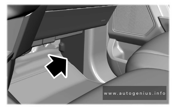
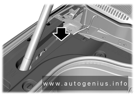
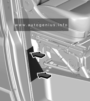
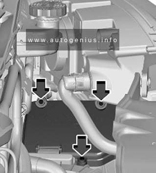
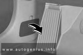
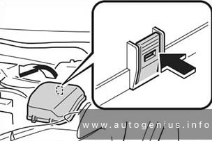
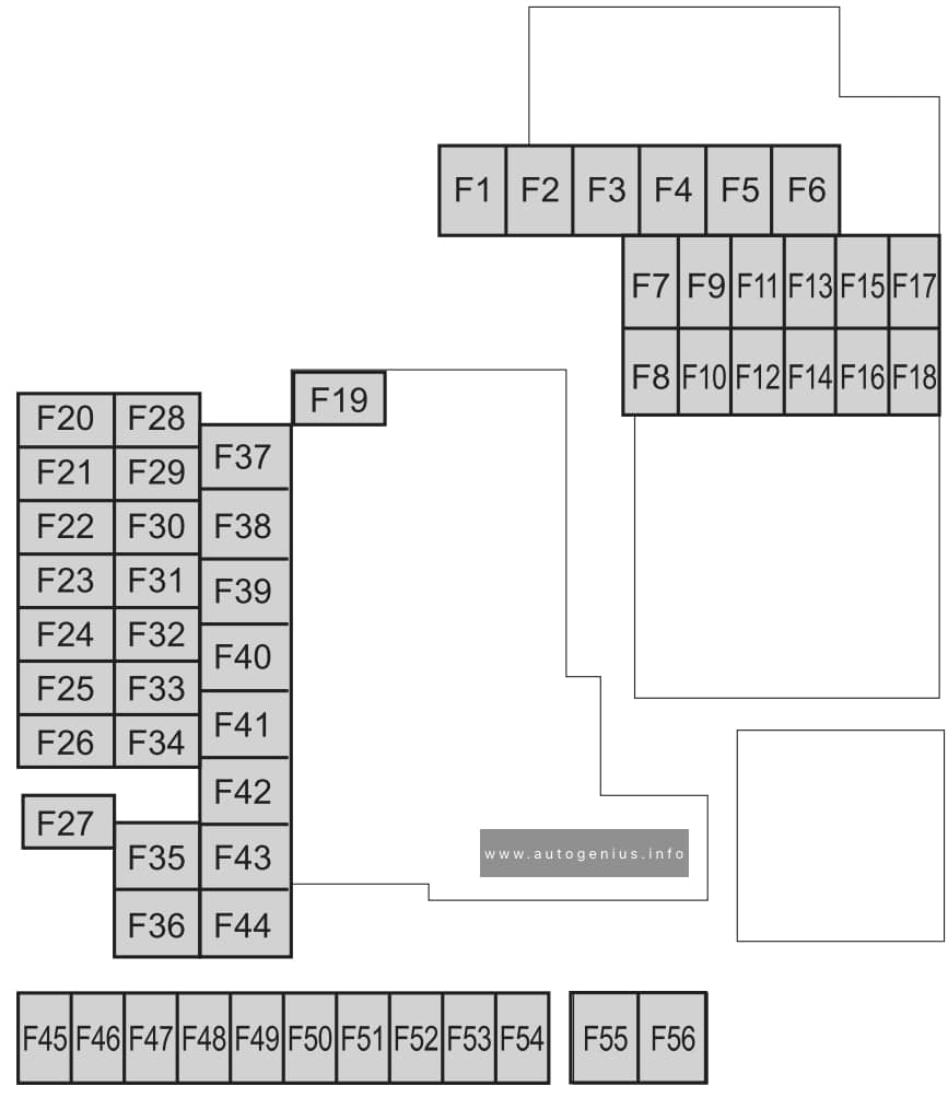
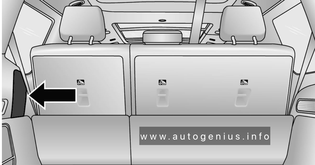
Luggage Compartment Fuse Box
Fuse box location
The Rear Power Distribution Center is located behind a trim cover in the rear driver’s side quarter panel.
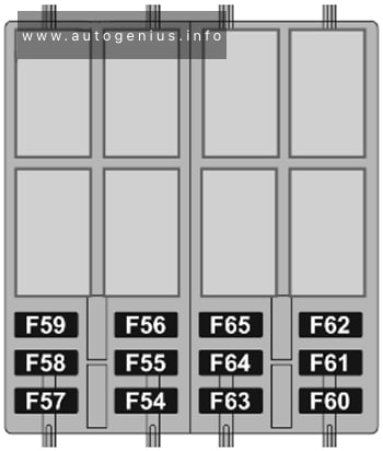
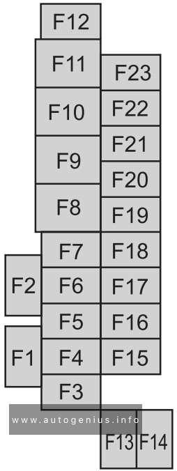
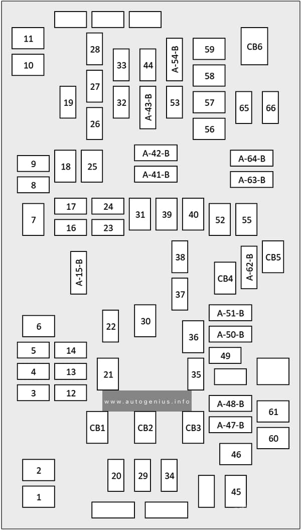
Fuse box diagram
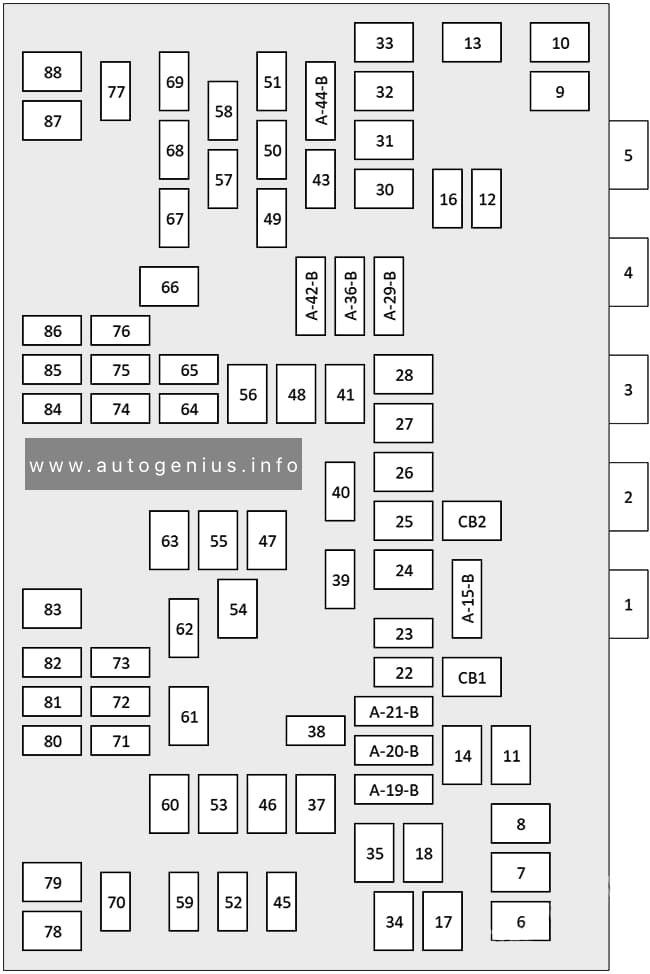
Assignment of the fuses in the Rear Power Distribution Center
| № | Cartridge Fuse | Micro Fuse | Description |
|---|---|---|---|
| F05 | 150A Gray | – | Underhood Power Distribution Center Battery Feed |
| F06 | – | – | Spare |
| F07 | – | – | Spare |
| F08 | – | – | Spare |
| F09 | – | – | Spare |
| F10 | – | – | Spare |
| F11 | – | – | Spare |
| F12 | – | – | Spare |
| F13 | 30A Pink | – | Air Compressor (Tire Inflator) |
| F14 | 25A Clear | – | MTR Sunshade Sunroof |
| F15A | – | – | Spare |
| F15B | – | 10A Red | Hands Free Liftgate / Rear Window Switches / MOD HVAC Cntrl Rr |
| F16 | – | – | Spare |
| F17 | – | – | Spare |
| F18 | 25A Clear | – | Power Liftgate Module |
| F19A | – | 10A Red | L2+ Driver Alert Lighting Module |
| F19B | – | 10A Red | Animation Lighting RR-LT |
| F20A | – | 15A Blue | Central ASAS Decision Module (CADM) – LO |
| F20B | – | – | Spare |
| F21A | – | – | Spare |
| F21B | – | 10A Red | Sunroof – Dual Pane 2nd & 3rd Row Seat SW-lllumination |
| F22 | – | – | Spare |
| F23 | – | 10A Red | Rear Seat Entertainment (Driver / Passenger) |
| F24 | – | – | Spare |
| F25 | 30A Pink | – | Mod Door MUX Passenger |
| F26 | – | – | Spare |
| F27 | – | – | Spare |
| F28 | 30A Pink | – | MOD Memory / Power Seat (Passenger Frt) |
| F29A | – | 10A Red | Animation Lighting RR-RT |
| F29B | – | 10A Red | Animation Lighting RR-LT |
| F30 | 30A Pink | – | MOD Memory / Power Seat (Driver Frt) |
| F31 | – | – | Spare |
| F32 | – | – | Spare |
| F33 | – | – | Spare |
| F34 | 30A Pink | – | MOD Door MUX Driver |
| F35 | 25A Clear | – | Integrated Trailer Tow Module #2 |
| F36A | – | 10A Red | Intelligent Event Base Lighting Module |
| F36B | – | – | Spare |
| F37 | 25A Clear | – | Integrated Trailer Tow Module #1 |
| F38 | – | – | Spare |
| F39 | – | – | Spare |
| F40 | – | 30A Green | MOD Audio Amplifier #1A |
| F41 | – | – | Spare |
| F42A | – | 10A Red | 2023: RSE Video USB Console Frt/Port Media Hub FPDM |
| F42B | – | – | Spare |
| F43 | – | – | Spare |
| F44A | – | 20A Yellow | 12 Volt Power Outlet Cargo Area (Ign) |
| F44B | – | 20A Yellow | 12 Volt Power Outlet Cargo Area (Battery) |
| F45 | – | 20A Yellow | MOD CRSM (Heated Seat RR RT) |
| F46 | 30A Pink | – | Folding Seat Module 3rd Row Feed #1 |
| F47 | – | – | Spare |
| F48 | – | – | Spare |
| F49 | – | – | Spare |
| F50 | – | 15A Blue | Seat Massage Driver Mod (SSMD)/ Seat Massage Passenger Mod (SSMP) |
| F51 | – | – | Spare |
| F52 | – | 20A Yellow | MOD CRSM (Heat Seat RR LT) |
| F53 | 30A Pink | – | Electronic Limited Slip Differential (ELSD) Rear #1 |
| F54 | – | – | Spare |
| F55 | 30A Pink | – | Folding Seat Modules 3rd Row Feed #2 |
| F56 | – | – | Spare |
| F57 | – | 10A Red | MOD HVAC RR / Mod Occupant Classic / CVPAM / Mod Parktronics/ ITCM |
| F58 | – | 15A Blue | 3rd Row Additional USB charge (Only LT – RT) / Port Pwr USB Console UBS (CH Only) |
| F59 | – | – | Spare |
| F60 | 25A Clear | – | RR_HVAC Blower |
| F61 | – | – | Spare |
| F62 | – | 20A Yellow | Module Seat Heater Frt (Driver) |
| F63 | 30A Pink | – | Assy Trailer Tow Receptacle B+ |
| F64 | – | – | Spare |
| F65 | – | – | Spare |
| F66 | 20A Blue | – | MOD Door MUX Passenger Rear-Smart Motor |
| F67 | – | 30A Green | MOD Audio Amplifier #1B |
| F68 | – | – | Spare |
| F69 | – | 20A Yellow | L2+ Central ASAS Decision Module (CADM) MID |
| F70 | – | 10A Red | Video Routing Module (VRM) |
| F71 | – | – | Spare |
| F72 | – | – | Spare |
| F73 | – | – | Spare |
| F74 | – | – | Spare |
| F75 | – | – | Spare |
| F76 | – | – | Spare |
| F77 | – | – | Spare |
| F78 | – | – | Spare |
| F79 | – | – | Spare |
| F80 | – | – | Spare |
| F81 | – | 20A Yellow | Module Seat Heater Frt (PASS) |
| F82 | – | 10A Red | Animation Lighting RR / Air Compressor (Tire Inflator)/ Animation Lighting Liftgate Taillamp |
| F83 | – | – | Spare |
| F84 | – | – | Spare |
| F85 | – | – | Spare |
| F86 | – | 15A Blue | Lumbar Support Driver & Passenger SW |
| F87 | – | – | Spare |
| F88 | 20A Blue | – | MOD Door MUX Driver Rear – Smart Motor |
| CB1 | – | 20A Yellow | Power Outlet RR |
| CB2 | – | – | Spare |
WARNING: Terminal and harness assignments for individual connectors will vary depending on vehicle equipment level, model, and market.