Holden Rodeo (RA; 2003 – 2006) – fuse box diagram
Year of production: 2003, 2004, 2005, 2006
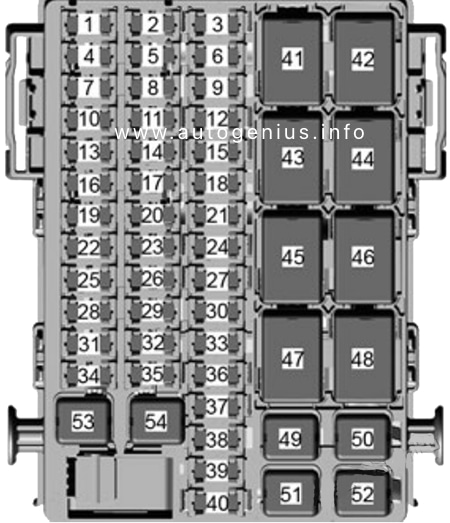
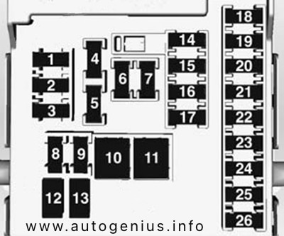
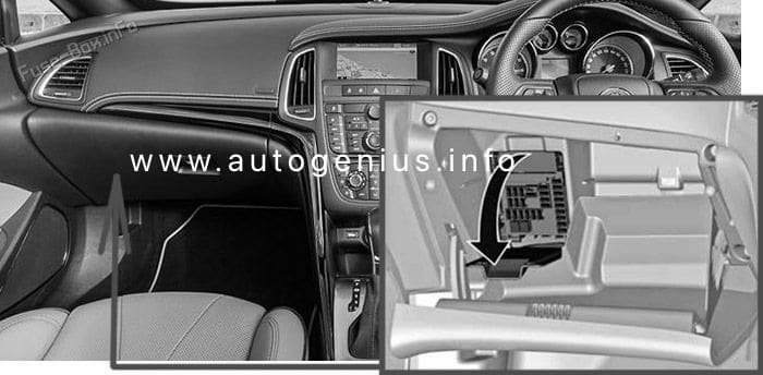
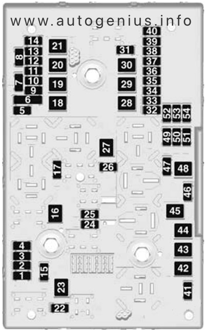
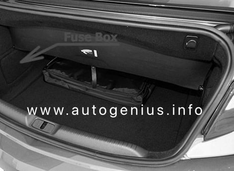
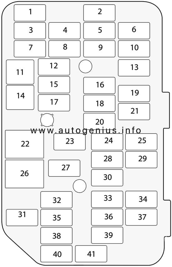
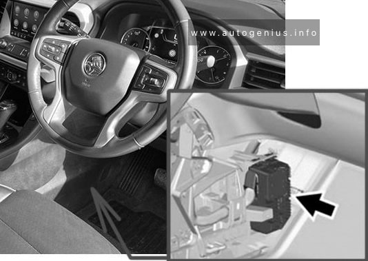
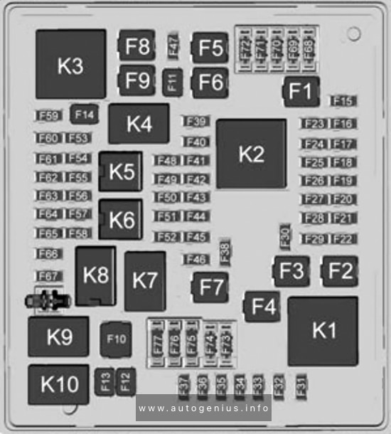
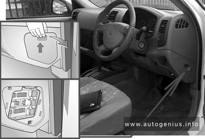
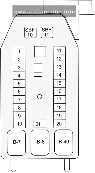
Passenger Compartment Fuse Box
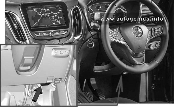
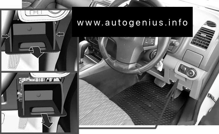
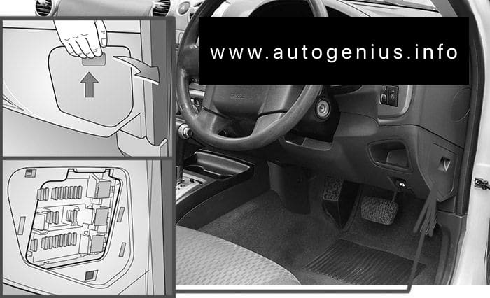
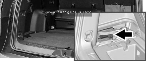
Fuse Box Location
The fuses are located behind a cover on the driver’s side of the dash panel.
To open the fuse cover in the dash panel, open the driver’s side door, pull the top of the cover out, then pivot downwards.
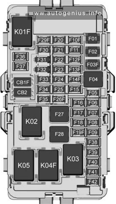
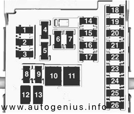
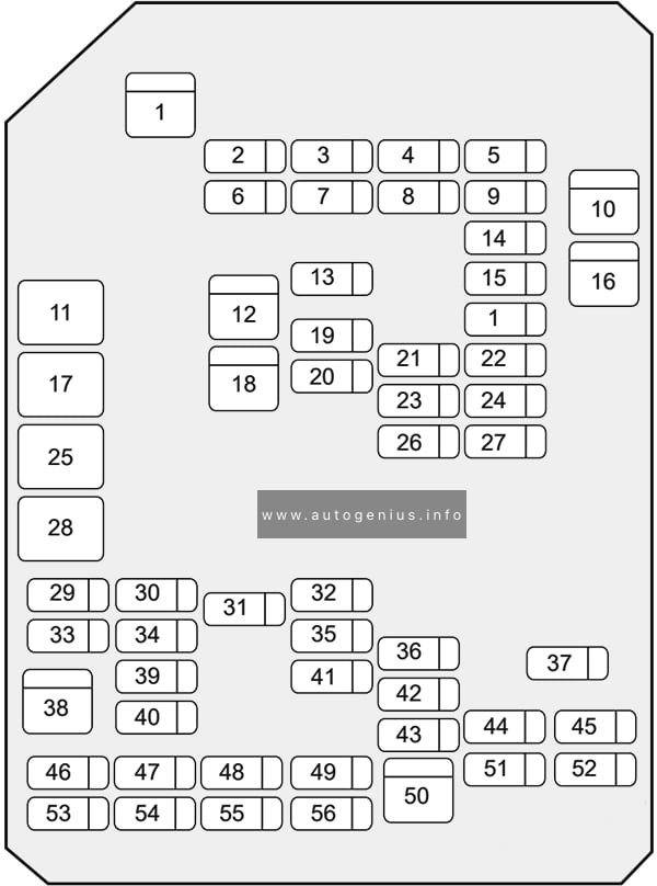
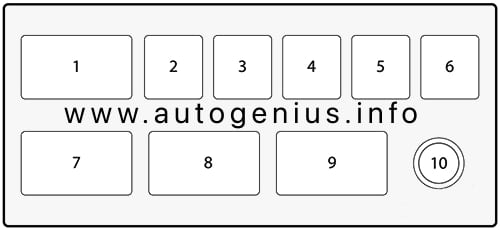
Fuse Box Diagram
| № | Amps | Function |
|---|---|---|
| 1 | – | – |
| 2 | 10A | ABS |
| 3 | – | – |
| 4 | 15A | Back Up |
| 5 | 15A | Meter |
| 6 | 10A | Turn |
| 7 | 15A | Elec. IG |
| 8 | 15A | Engine |
| 9 | 20A | Frt Wiper/Washer |
| 10 | 15A | Egr |
| 11 | 10A | Audio |
| 12 | 15A/20A | Cigar/Acc Socket |
| 13 | 15A | Audio (+B) |
| 14 | 20A | Door Lock |
| 15 | 10A | Meter (+B) |
| 16 | 10A | Dome Light |
| 17 | 10A | Anti Theft |
| 18 | 15A | Stop |
| 19 | 15A | Acc Socket (according to 2003) |
| 20 | 10A | Starter |
| 21 | 10A | SRS |
| SBF10 | 20A | RR Def (Slow blow fuse) |
| SBF11 | 30A | Power Window (Slow blow fuse) |
| B-7 | Rear defogger relay | |
| B-8 | Power window relay | |
| B-40 | Acc Socket relay (according to 2003) |
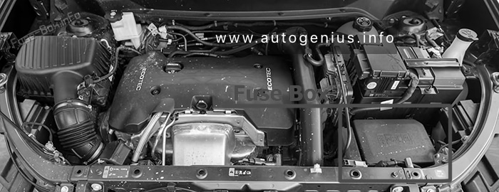
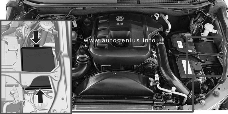
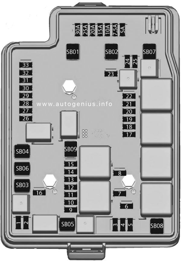
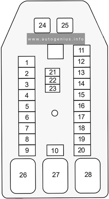
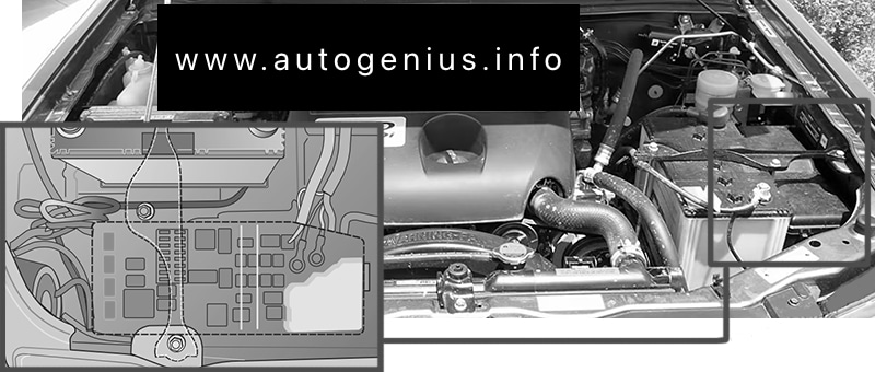
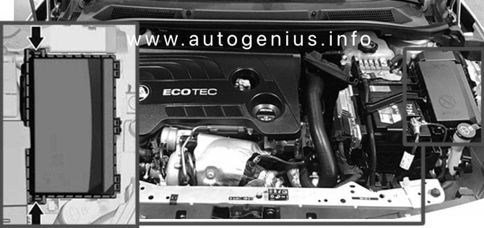
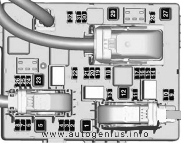
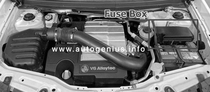
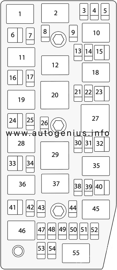
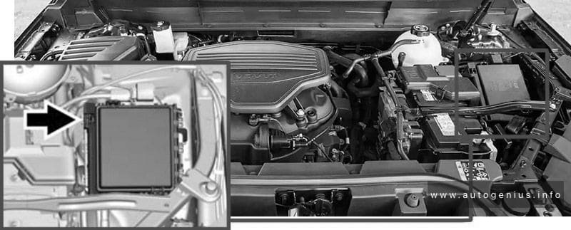
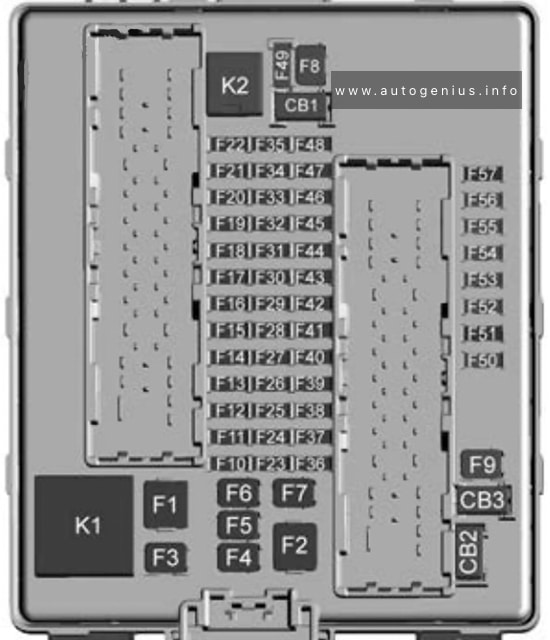
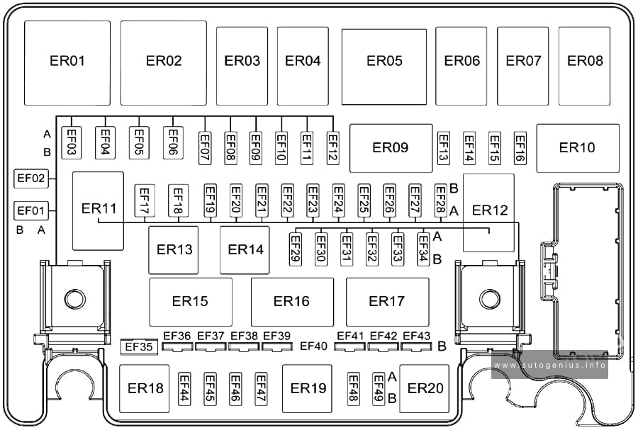
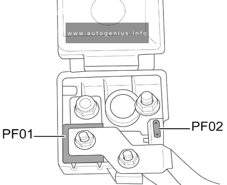
Engine Compartment Fuse Box
Fuse Box Location
This fuse box is located on the passenger side of the engine compartment near the battery.
To remove the cover, press the catch on the side of the fuse box towards the engine and release the two tabs at the opposite side.

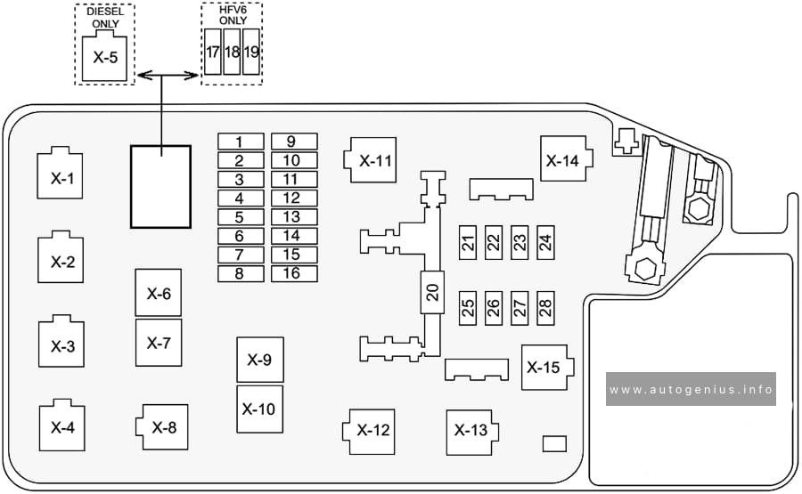
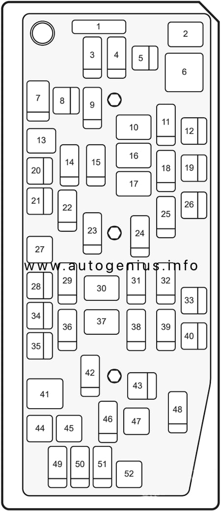
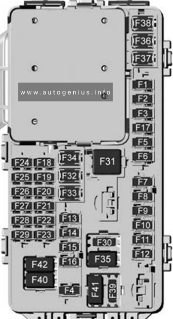
Fuse Box Diagram
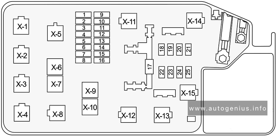
| № | Amps | Function |
|---|---|---|
| 1 | 10A/15A/20A | ECM |
| 2 | 10A/15A | 6VE1: ECM HFV6: O2 pre heat 4JH1-TC: RR Fog |
| 3 | 10A/15A | C24SE: Frt Fog 6VE1, HFV6: ECM (B) 4JH1-TC: Frt Fog |
| 4 | 10A/15A | C24NE, C24SE: ACG (S) 6VE1: Frt Fog HFV6: TCM/PIM (B) 4JH1-TC: ACG (S) (according to 2003) |
| 5 | 10A | Illumination (according to 2003) C24SE: Illumination (according to 2006) HFV6, 4JH1-TC: Illumination & Tail (right) (according to 2006) |
| 6 | 10A | Tail light (according to 2003) C24SE: Illumination (according to 2006) HFV6, 4JH1-TC: Illumination & Tail (left) (according to 2006) |
| 7 | 10A | H/Light (right) |
| 8 | 10A | H/Light (left) |
| 9 | 10A/20A | C24NE, C24SE: Fuel Pump HFV6, 4JH1-TC: Trailer (according to 2006) 6VE1: O2 Sensor (according to 2003) |
| 10 | 10A/20A | C24NE, C24SE: O2 Sensor 6VE1: Fuel Pump HFV6: O2 Heat Post 4JH1-TC: ACG (S) |
| 11 | 15A | HFV6: Coil-RH |
| 12 | 15A | HFV6: Coil-LH |
| 13 | 10A | A/C |
| 14 | 10A | 4WD |
| 15 | 10A | Horn |
| 16 | 10A/15A | Hazard |
| 17 | 80A/100A | Main fuse |
| 18 | 20A | HFV6: Frt Fog 4JH1-TC: Cond, Fan |
| 19 | 50A/60A | HFV6: Rad, Fan 4JH1-TC: Glow |
| 20 | 20A/30A | C24NE, C24SE, 6VE1: Cond, Fan HFV6: Fuel Pump 4JH1-TC: ECM |
| 21 | 40A | IG 1 |
| 22 | 40A | 6VE1, 4JH1-TC: ABS-1 (according to 2003) HFV6, 4JH1-TC: IG 1 (according to 2006) |
| 23 | 30A/40A | 6VE1, 4JH1-TC: ABS-2 |
| 24 | 30A | Blower |
| 25 | 50A | IG 2 |
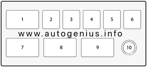
| Relays: | ||
| X-1 | Tail light | |
| X-2 | Fuel pump (according to 2003) 4JH1-TC (according to 2006): Frt Fog |
|
| X-3 | Horn | |
| X-4 | Dimmer | |
| X-5 | 6VE1: Fog light (according to 2003) 4JH1-TC: Glow |
|
| X-6 | C24NE, 6VE1: Starter (according to 2003) C24SE: Starter 4JH1-TC: Starter cut |
|
| X-7 | Cond, Fan (according to 2003) C24SE, 4JH1-TC (according to 2006): H/Light |
|
| X-8 | 4JH1-TC: Starter (according to 2006) | |
| X-9 | 6VE1: Hazard (right) (according to 2003) C24SE: FRT Fog light (according to 2006) 4JH1-TC: Cond fan (according to 2006) |
|
| X-10 | 6VE1: Hazard (left) (according to 2003) C24SE: Cond fan (according to 2006) HFV6: FRT Fog light (according to 2006) |
|
| X-11 | Heater | |
| X-12 | Headlights (according to 2003) HFV6: ECM Main (according to 2006) |
|
| X-13 | 6VE1: ECM Main (according to 2003) C24SE: Starter cut (according to 2006) HFV6: Starter (according to 2006) 4JH1-TC: ECM Main (according to 2006) |
|
| X-14 | A/C compressor | |
| X-15 | Thermo (according to 2003) C24SE, 4JH1-TC: Thermo (according to 2006) HFV6: H/light (according to 2006) |
|
WARNING: Terminal and harness assignments for individual connectors will vary depending on vehicle equipment level, model, and market.