Cadillac ATS (2014 – 2015) – fuse and relay box diagram
Year of production: 2014, 2015
The Cadillac ATS, a compact executive 4-door sedan, was manufactured from 2013 to 2019. This article provides fuse box diagrams for the 2014 and 2015 models, along with information on the location of the fuse panels within the vehicle and details on the function and layout of each fuse and relay.
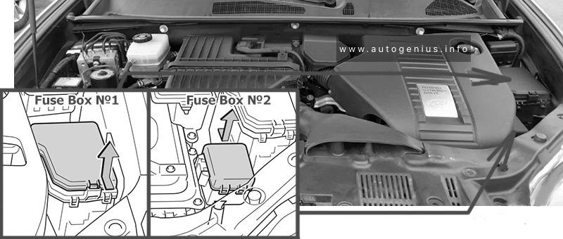
Engine compartment
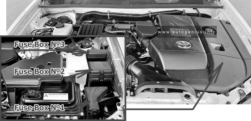
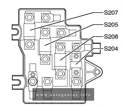
Fuse box location
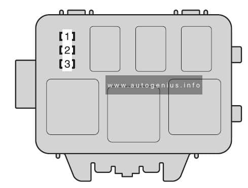
The underhood fuse block is on the passenger side of the engine compartment.
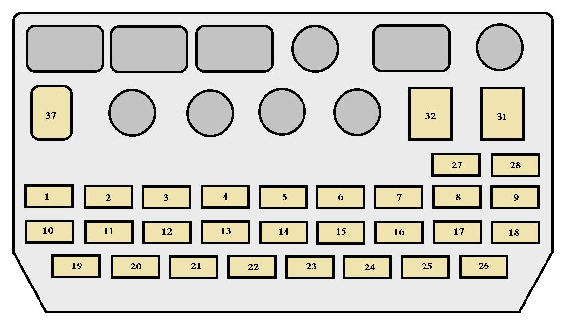
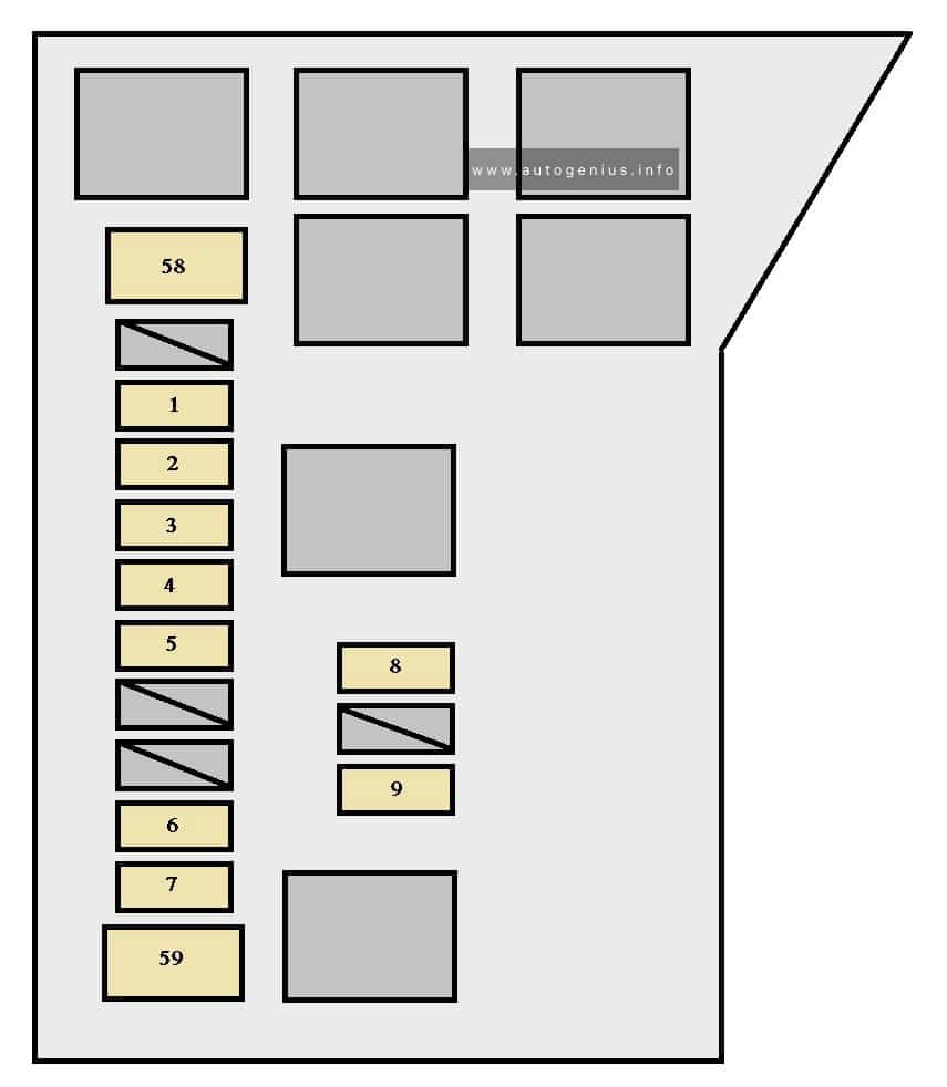
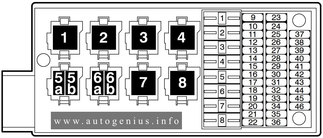
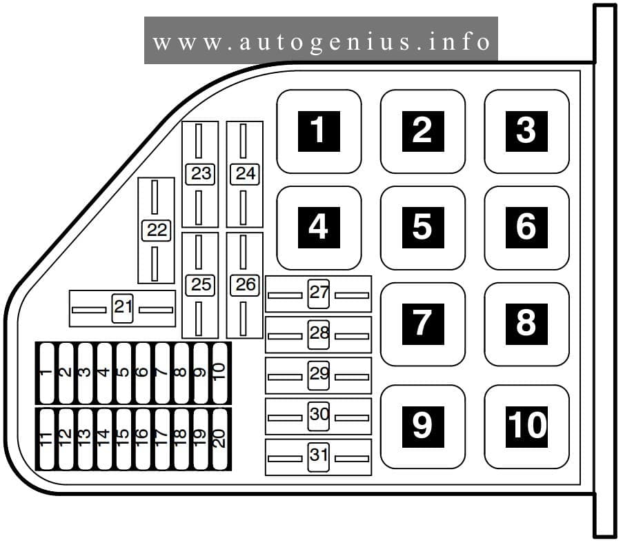
Fuse box diagram
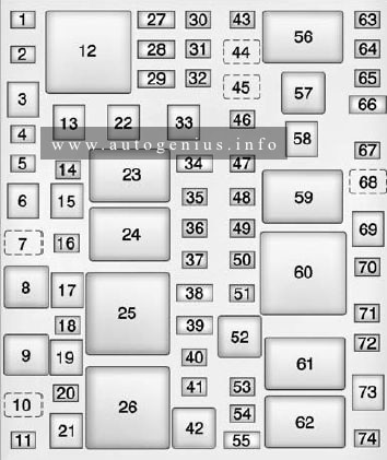
Assignment of the fuses and relays in the engine compartment (2014-2015)
| Number | Usage |
| 1 | Not Used |
| 2 | Not Used |
| 3 | Not Used |
| 4 | Body Control Module 6 |
| 5 | Not Used |
| 6 | Driver Power Seat |
| 7 | Not Used |
| 8* | Headlamp Washer Relay |
| 9 | Not Used |
| 10 | Not Used |
| 11 | Not Used |
| 12 | Not Used |
| 13 | Passenger Power Seat |
| 14 | Body Control Module 5 |
| 15 | Passive Entry/Passive Start |
| 16 | Not Used |
| 17* | Headlamp Washer |
| 18 | Not Used |
| 19 | Antilock Brake System Pump |
| 20 | Antilock Brake System Valve |
| 21* | AIR Pump |
| 22 | Not Used |
| 23 | Wiper Control Relay |
| 24 | Wiper Speed Relay |
| 25 | Engine Control Module Relay |
| 26* | AIR Pump Relay |
| 27 | Spare/Heated Seat 2 |
| 28 | Body Control Module 1/Spare |
| 29* | AFS AHL/Pedestrian Protection |
| 30 | Passenger Window Switch |
| 31 | Body Control Module 7 |
| 32 | Sunroof |
| 33 | Front Wiper |
| 34 | AOS Display/MIL Ignition |
| 35 | Rear Electrical Center Ignition |
| 36 | Spare PT Fuse |
| 37 | Oxygen Sensor |
| 38 | Ignition Coils/Injectors |
| 39 | Ignition Coils/Injectors/Spare |
| 40 | Engine Control Module |
| 41 | Fuel Heater |
| 42* | AIR Solenoid Relay |
| 43 | Washer |
| 44 | Rear Washer Relay |
| 45 | Front Washer Relay |
| 46 | Not Used |
| 47 | Instrument Panel Body Ignition |
| 48 | Fuel System Control Module Ignition |
| 49 | Heated Steering Wheel |
| 50* | Steering Column Lock |
| 51* | Coolant Pump |
| 52* | Coolant Pump Relay |
| 53 | Air Conditioning Compressor Clutch |
| 54* | AIR Solenoid |
| 55 | Transmission Control Module/Spare |
| 56* | Headlamp Low Relay |
| 57 | Headlamp high Relay |
| 58 | Starter |
| 59 | Starter Relay |
| 60 | Run/Crank Relay |
| 61* | Vacuum Pump Relay |
| 62 | Air Conditioning Control Relay |
| 63* | Adaptive Headlamp Leveling |
| 64* | Left High Intensity Discharge Headlamp |
| 65* | Right High Intensity Discharge Headlamp |
| 66 | Headlamp High Left/Right |
| 67 | Horn |
| 68 | Horn Relay |
| 69 | Cooling Fan |
| 70 | Aero Shutter |
| 71 | Transmission Control Module Ignition |
| 72 | Engine Control Module Ignition |
| 73* | Brake Vacuum Pump |
| 74 | Not Used |
| * Optional | |
Passenger compartment
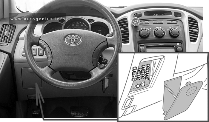
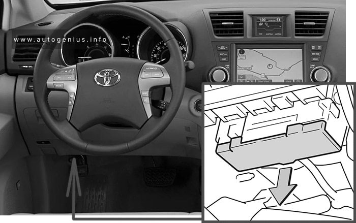
Fuse box location
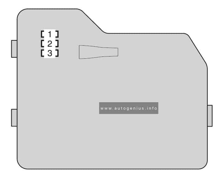
The instrument panel fuse block is in the end of the driver side of the instrument panel.
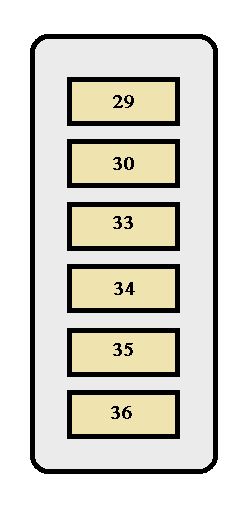
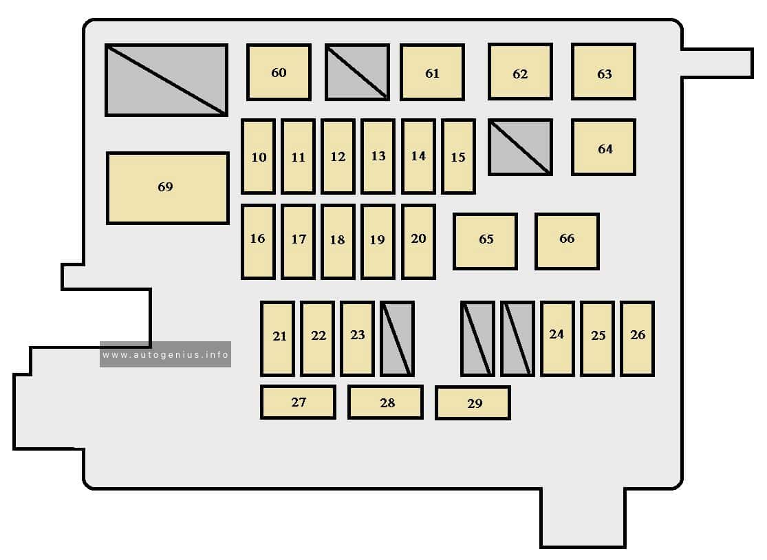
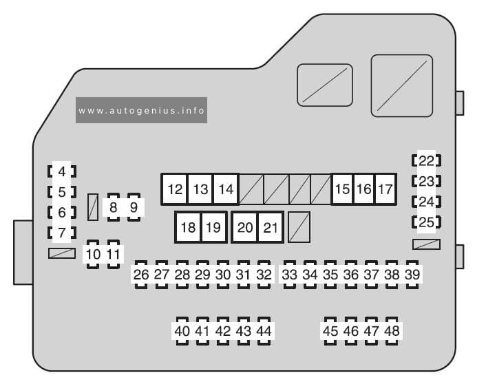
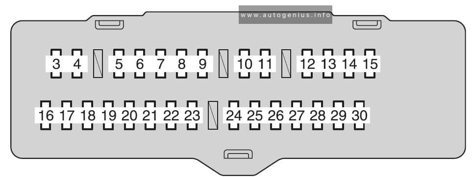
Fuse box diagram
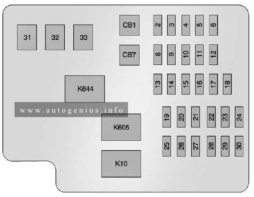
Assignment of the fuses and relays in the passenger compartment (2014-2015)
| Number | Usage |
| 2 | Spare |
| 3 | Electric Steering Column Lock |
| 4 | Data Link Connector |
| 5 | Heater, Ventilation, and Air Conditioning Control |
| 6 | Tilt and Telescope Steering Column |
| 8 | Spare |
| 9 | Spare |
| 10 | Shunt |
| 11 | Spare |
| 12 | Spare |
| 13 | Spare |
| 14 | Spare |
| 16 | Spare |
| 17 | Spare |
| 18 | Spare |
| 19 | Spare |
| 20 | Spare |
| 21 | Spare |
| 22 | Sensing Diagnostic Module/Automatic Occupant Sensing |
| 23 | Radio/DVD/Heater, Ventilation, and Air Conditioning |
| 24 | Display |
| 25 | Heated Steering Wheel |
| 26 | Spare |
| 27 | Switches |
| 28 | Spare |
| 29 | Spare |
| 30 | Spare |
| J Case Fuses | Usage |
| 31 | Spare |
| 32 | Spare |
| 33 | Front Heater, Ventilation, and Air Conditioning Blower |
| Circuit breakers | Usage |
| CB1 | Retained Accessory Power/Accessory Power Outlet Power |
| CB7 | SPare |
| Relays | Usage |
| K10 | Retained Accessory Power/Accessory |
| K605 | Spare |
| K609 | Spare |
Rear compartment
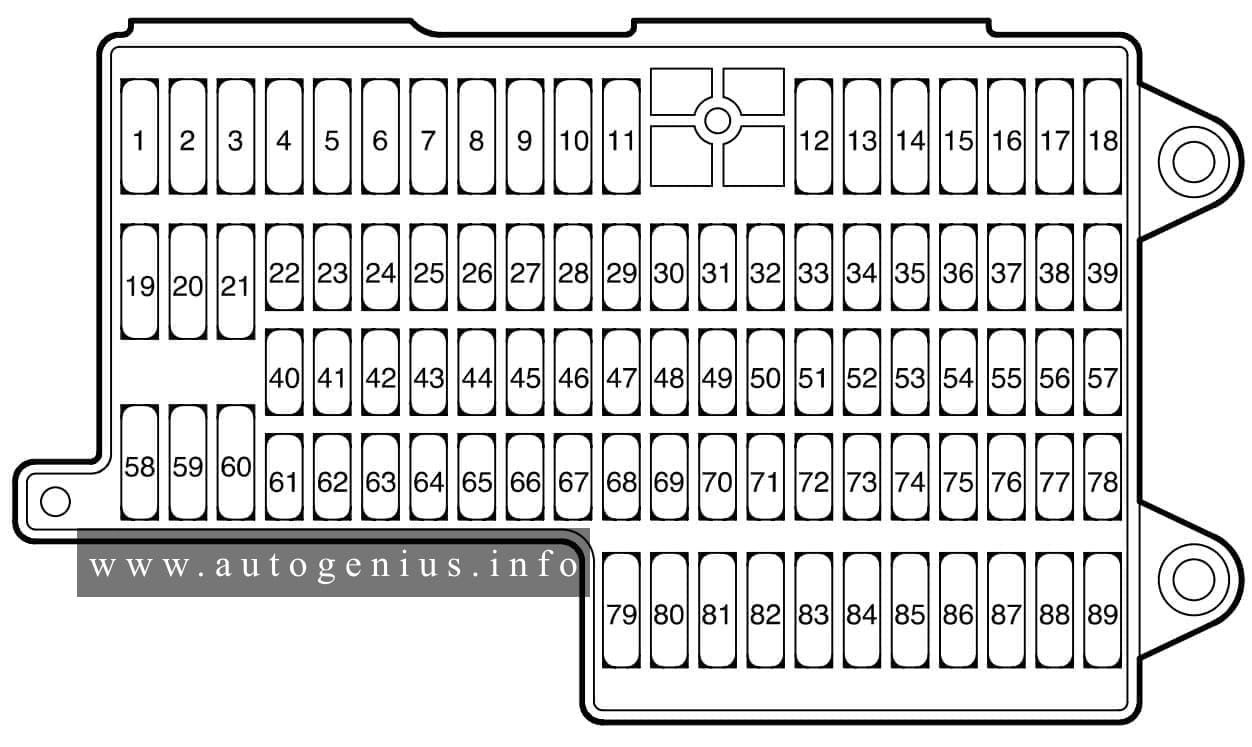
Fuse box location
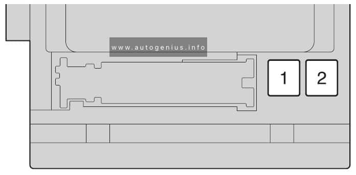
The rear compartment fuse block is behind a cover on the driver side of the rear compartment.
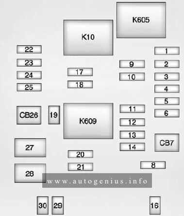
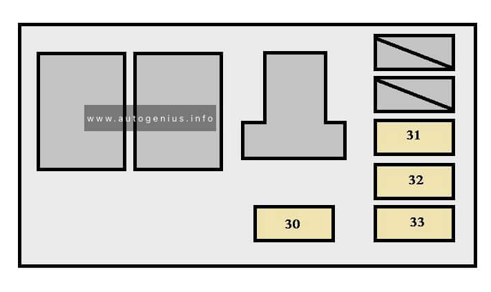
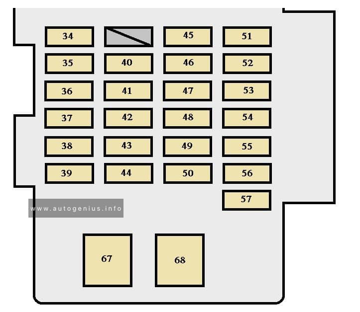
Fuse box diagram
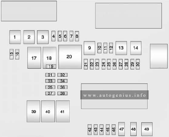
Assignment of the fuses and relays in the rear compartment (2014-2015)
| Number | Usage |
| 1 | Not Used |
| 2 | Left Window |
| 3 | Body Control Module 8 |
| 4 | A/C Inverter |
| 5 | Passive Entry Passive Start Battery 1 |
| 6 | Body Control Module 4 |
| 7 | Heated Mirrors |
| 8 | Amplifier |
| 9 | Rear Window Defogger |
| 10 | Not Used |
| 11 | Trailer Connector |
| 12 | OnStar (If Equipped) |
| 13 | Right Window |
| 14 | Electric Parking Brake |
| 15 | Not Used |
| 16 | Trunk Release |
| 17 | Run Relay |
| 18 | Logistics Relay |
| 19 | Logistics Fuse |
| 20 | Rear Window Defogger Relay |
| 21 | Mirror Window Module |
| 22 | Not Used |
| 23 | Canister Vent |
| 24 | Body Control Module 2 |
| 25 | Rear Vision Camera |
| 26 | Not Used |
| 27 | SBZA/LDW/EOCM |
| 28 | Trailer/Sunshade |
| 29 | Not Used |
| 30 | Semi-Active Damping System |
| 31 | Transfer Case Control Module |
| 32 | Theft Module/Universal Garage Door Opener/Rain Sensor |
| 33 | UPA |
| 34 | Radio/DVD |
| 35 | Not Used |
| 36 | Trailer |
| 37 | Fuel Pump/Fuel System Control Module |
| 38 | Not Used |
| 39 | Not Used |
| 40 | Not Used |
| 41 | Not Used |
| 42 | Memory Seat Module |
| 43 | Body Control Module 3 |
| 44 | Not Used |
| 45 | Battery Regulated Voltage Control |
| 46 | Engine Control Module Battery |
| 47 | Not Used |
| 48 | Not Used |
| 49 | Trailer Module |
WARNING: Terminal and harness assignments for individual connectors will vary depending on vehicle equipment level, model, and market.