Jaguar E-Pace (X540; 2021) – fuse and relay box diagram

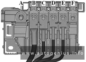
Jaguar E-Pace (X540; 2021) – fuse and relay box diagram

Year of production: 2021


The Jaguar E-Pace (X540), a subcompact luxury crossover SUV, has been in production since 2017. In this article, you’ll find fuse box diagrams for the 2021 models, along with details on the locations of the fuse panels within the vehicle and explanations of each fuse’s function and layout.


Passenger compartment

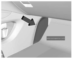
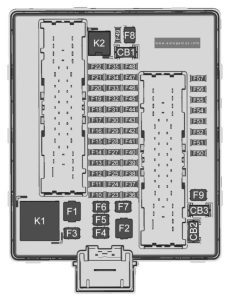
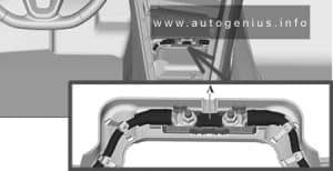
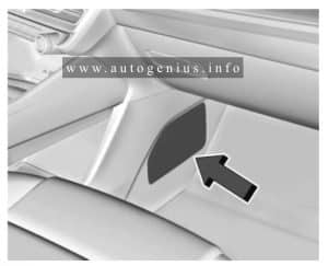
Fuse box location

The fuse box is located below the glove box.


Fuse Box Diagrams

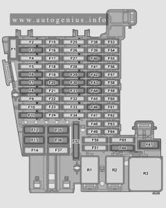
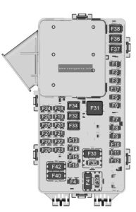
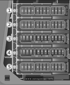
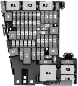
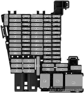
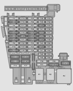
Jaguar E-Pace (X540; 2021) - fuses and relay box diagram - passenger compartment
Jaguar E-Pace (X540; 2021) – fuses and relay box diagram – passenger compartment


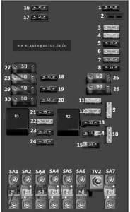
Assignment of the fuses in the passenger compartment fuse box

Rating Protected Component
1 30A Front passenger’s seat.
2 30A Driver’s seat.
3 25A Passenger’s door module.
4 25A Driver’s door module.
5 5A Keyless entry.
6
7
8 5A PHEV junction box.
9 5A RF receiver.
10 5A Battery back-up sounder.
11 5A Instrument panel.
12 20A Fuel system.
13 5A Diagnostic socket.
14 5A Vehicle immobiliser.
15 5A Steering wheel.
16 20A Keyless entry.
17
18 20A Front blind.
19 20A Front passenger’s heated or climate seat.
20 5A Mirror. Camera.
21 5A Blind spot monitor.
22
23
24 10A Head-Up Display (HUD) module.
25 10A Instrument panel.
26 20A Auxiliary power socket.
27
28
29 5A Adaptive cruise control.
30 20A Driver’s heated and climate seat control.
31 5A Ignition feed.
32 5A USB hub.
33
34 15A Rear folding seats.
35 15A Infotainment system.
36 10A Audio video output.
37 15A Seat switches and memory.
38 20A Auxiliary power socket.
39 5A Electrochromic mirror.
40
41 10A Heated steering wheel.
42
43 20A Heating and ventilation system.
44
45 40A Body control module.
46 2A Singapore road pricing electronic toll (Right-Hand Drive vehicles only).
47 40A Body control module.
48
49 40A Infotainment system amplifier.
50


Engine Compartment Fuse Box

Fuse Box Diagrams

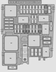
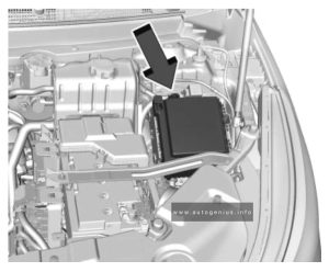
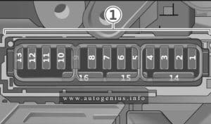
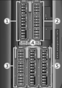
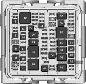
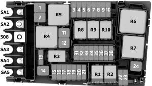
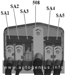
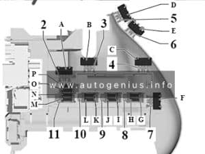
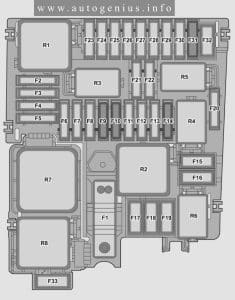
Jaguar E-Pace (X540; 2021) - fuses and relay box diagram - engine compartment
Jaguar E-Pace (X540; 2021) – fuses and relay box diagram – engine compartment


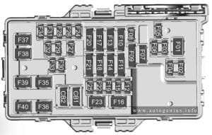
Assignment of the fuses in the engine compartment fuse box

Rating Protected Component
1
2 15A Water charge air cooler.
3 10A Engine management system.
4
5 15A Engine management system.
6 15A Engine management system.
7
8 10A Plug-in Hybrid Electric Vehicles only: PHEV control/PHEV heater pump.
9 15A Intercooler water pump.
10 15A PHEV only: inverter.
11 5A 2021: Steering wheel.
12 5A Starter switch / 48v system.
13
14
15 15A Engine management system.
16
17 15A Fuel system. Engine management system. Exhaust sensors.
18 30A Glow plugs.
19 40A Engine control module.
20 40A Brake control module. Battery.
21 30A Glow plugs.
22 40A Blower motor.
23 10A Front fog lights.
24 10A Engine cooling.
25
26 10A Diesel exaust fluids.
27 10A Engine management system.
28 25A Fuel pump.
29 25A Front windshield washer.
30
31 25A Rear window washer.
32
33 10A Steering wheel rotary coupler.
34 25A Right-side headlight.
35 25A Left-side headlight.
36 10A Driver assistance systems.
37 15A Horn.
38 10A PHEV only: battery/belt integrated starter-generator.
39 20A 4WD.
40 25A Power wash pump.
41 5A Acoustic vehicle alerting system.
42 15A PHEV only: Hybrid coolant pump.
43
44 40A Right-side front heated windshield.
45 40A PHEV only: Transmission oil pump.
46
47 40A Left-side front heated screen.
48 40A Starter motor.
49 30A Electric Parking Brake (EPB).
50
51 40A Diesel motor.
52 30A Windshield wiper motor.


Luggage Compartment Fuse Box

Fuse Box Diagrams

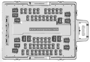
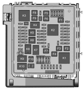
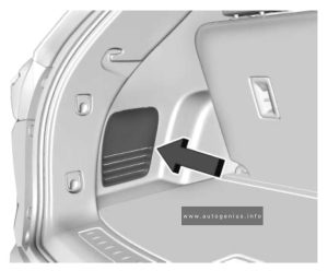
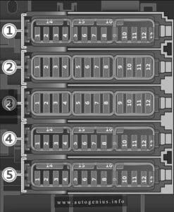
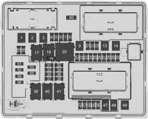
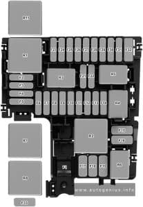
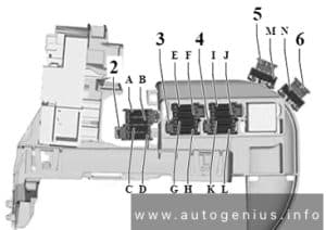
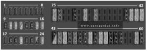
Jaguar E-Pace (X540; 2021) - fuses and relay box diagram - luggage compartment
Jaguar E-Pace (X540; 2021) – fuses and relay box diagram – luggage compartment


Assignment of the fuses in the luggage compartment fuse box

Rating Protected Component
1 15A Rear wiper.
2
3 5A Telematics.
4 5A Fuel Burning Heater (FBH).
5 25A Fuel pump.
6 30A Power tailgate.
7 5A Rear climate and comfort systems.
8
9
10
11 25A Right-side rear door module.
12 20A Trailer.
13
14 25A Left-side rear door module.
15 10A Near field sensing module.
16
17
18
19 30A Driveline.
20
21 20A Accessory socket.
22
23
24 5A USB socket.
25 5A Vehicle battery.
26 20A Rear heated seat module.
27
28
29 10A Wireless phone charger.
30
31
32
33 20A Trailer socket.
34 10A Chassis control module.
35 30A Driveline.
36
37
38
39
40 10A USB charger.
41 20A Right-side heated rear seat.
42 20A Rear console accessory socket.
43
44 30A Heated rear screen.
45
46
47 30A Trailer socket.
48 30A Deployable towbar.
49 50 Auxiliary heater.
50 25A Diesel Exhaust Fluid (DEF).

WARNING: Terminal and harness assignments for individual connectors will vary depending on vehicle equipment level, model, and market.

Jaguar E-Pace (X540; 2017 – 2020) – fuse and relay box diagram

Jaguar E-Pace (X540; 2017 – 2020) – fuse and relay box diagram

Year of production: 2017, 2018, 2019, 2020


The Jaguar E-Pace (X540), a subcompact luxury crossover SUV, has been in production since 2017. In this article, you’ll find fuse box diagrams for the 2017 through 2020 models, along with details on the locations of the fuse panels within the vehicle and explanations of each fuse’s function and layout.


Passenger compartment

Fuse box location

The fuse box is located below the glove box.


Fuse Box Diagrams

Jaguar E-Pace (X540; 2017 - 2020) - fuses and relay box diagram - passenger compartment
Jaguar E-Pace (X540; 2017 – 2020) – fuses and relay box diagram – passenger compartment


Assignment of the fuses in the passenger compartment fuse box

Rating Protected Component
1 30A Front passenger’s seat.
2 30A Driver’s seat.
3 25A Passenger’s door module.
4 25A Driver’s door module.
5 5A Keyless entry.
6
7
8
9 5A Tire Pressure Monitoring System (TPMS).
10 5A Battery back-up sounder.
11 5A Instrument panel.
12 20A Fuel system.
13 5A Rear seats.
14 5A Vehicle immobiliser.
15 5A Steering wheel.
16 20A Keyless entry.
17 5A Brake pedal switch.
18 20A Front blind.
19 20A Front passenger’s heated or climate seat.
20 5A Mirror. Camera.
21 5A Blind spot monitor.
22 5A Camera.
23
24 10A 2021-2023: Head-Up Display (HUD) module.
25 10A Instrument panel.
26 20A Cigar lighter.
27
28 10A Head-Up Display (HUD) and cooling fan.
29 5A Adaptive cruise control.
30 20A Driver’s heated and climate seat control.
31 5A Powered tailgate.
32 5A Driver door module.
33 10A Audio amplifier.
34 15A Infotainment system.
35 15A Infotainment system.
36 10A Audio video output.
37 15A Seat switches and memory.
38 20A Cubby box auxiliary power socket.
39
40
41 10A Heated steering wheel.
42 5A Steering wheel.
43 20A Heating and ventilation system.
44
45 40A Body control module.
46
47 40A Body control module.
48
49 40A Infotainment system amplifier.
50 20A Amplifier module.


Engine Compartment Fuse Box

Fuse Box Diagrams

Jaguar E-Pace (X540; 2017 - 2020) - fuses and relay box diagram - engine compartment
Jaguar E-Pace (X540; 2017 – 2020) – fuses and relay box diagram – engine compartment


Assignment of the fuses in the engine compartment fuse box

Rating Protected Component
1 30A Engine control module.
2 5A Electrical power management.
3 80A Electric Power Assisted Steering System (EPAS). Engine management system.
4 60A Glow plugs (diesel only).
5 100A Engine cooling.
6 15A Engine management system.
7 15A Engine management system.
8 15A Engine management system.
9 10A Engine management system.
10 5A Fuel pump.
11 10A Engine management system.
12 10A Engine management system.
13
14 10A Engine cooling / Engine management system.
15 40A Engine management system.
16 100A Auxiliary heater.
17 60A Passenger compartment fuse box.
18 60A Passenger compartment fuse box.
19 60A Loadspace fuse box.
20 60A Loadspace fuse box.
21 60A Electrical power management.
22 30A Front windscreen wipers.
23 40A Passenger compartment fuse box.
24 40A Starter motor (diesel automatic only).
25 40A Anti-lock Braking System (ABS).
26 40A Anti-lock Braking System (ABS).
27 40A Passenger compartment fuse box.
28 40A Heater blower motor.
29 30A Electric trailer brake (Australia only).
30 15A Spare.
31 15A Horns.
32 10A Spare.
33 5A Horn. Heated windscreen. Fuel pump.
34 40A Left-side heated windscreen.
35 40A Right-side heated windscreen.
36 5A Engine management system. Air Conditioning (A/C).
37 20A Fuel pump.
38 15A Transmission control module.
39 10A Front fog lights.
40 20A Right-side headlight.
41 20A Left-side headlight.
42
43
44
45


Luggage Compartment Fuse Box

Fuse Box Diagrams

Jaguar E-Pace (X540; 2017 - 2020) - fuses and relay box diagram - luggage compartment
Jaguar E-Pace (X540; 2017 – 2020) – fuses and relay box diagram – luggage compartment


Assignment of the fuses in the luggage compartment fuse box

Rating Protected Component
1 15A Rear wiper.
2 20A Deployable sidesteps.
3 5A Telematics.
4 5A Fuel Burning Heater (FBH).
5 10A/25A Fuel pump.
6 30A Power tailgate.
7
8
9 Battery spare.
10
11 25A Right-side rear door module.
12 20A Trailer.
13 5A All Wheel Drive (AWD).
14 25A Left-side rear door module.
15
16
17
18
19 30A Driveline.
20
21 20A Accessory socket.
22
23
24 5A Wade sensing.
25 5A Vehicle battery.
26 20A Rear heated seat module.
27 5A Windows.
28 5A Vehicle diagnostics.
29
30
31
32
33 20A Trailer socket.
34 10A Chassis control module.
35 30A Driveline.
36 20A Fuel pump.
37
38 5A Fan spare.
39 20A Rear control spare.
40 10A USB charger.
41 20A Right-side heated rear seat.
42 20A Rear console accessory socket.
43
44 30A Heated rear screen.
45
46
47 30A Driveline.
48 30A Deployable towbar.
49
50 25A Heater.

WARNING: Terminal and harness assignments for individual connectors will vary depending on vehicle equipment level, model, and market.
Ford F-750 (2024 – 2025) – fuse and relay box diagram

Ford F-750 (2024 – 2025) – fuse and relay box diagram

Year of production: 2024, 2025


This article focuses on the facelifted eighth-generation Ford F-650 and F-750, produced from 2021 to the present. It includes fuse box diagrams for the 2024 and 2025 models, provides information on the locations of the fuse panels within the vehicle, and outlines the function and layout of each fuse.


Passenger compartment

Fuse box location

The fuse panel is in the passenger footwell. Remove the panel cover to access the fuses.


Fuse Box Diagrams

Ford F-750 (2024 - 2025) - fuses and relay box diagram - passenger compartment
Ford F-750 (2024 – 2025) – fuses and relay box diagram – passenger compartment


Assignment of the fuses in the passenger compartment fuse box

Rating Protected Component
1 Not used.
2 10 A Right-hand and left-hand front door lock switch, Telescopic mirror switch, Right-hand and left-hand front window switch (two window units), Right-hand and left-hand front window motor. Inverter.
3 7.5 A Power mirror switch.
4 20 A Ancillary translator module.
5 Not used.
6 Not used.
7 10 A Smart data link connector power, Air brake diagnostic connector.
8 Not used.
9 Not used.
10 Not used.
11 Not used.
12 7.5 A Smart data link connector.
13 7.5 A Instrument Cluster, Steering column control module.
14 Not used.
15 15 A Climate control module.
16 Not used.
17 Not used.
18 7.5 A Yaw sensor, Electronic stability control and non-electric stability control.
19 5 A Telematics control unit module.
20 5 A Ignition switch.
21 Not used.
22 Not used.
23 30 A Left-hand front window motor.
24 Not used.
25 Not used.
26 30 A Right-hand front motor window.
27 Not used.
28 Not used.
29 15 A Relay folding mirror.
30 5 A Brake signal for air brake, Customer access stop lamp signal, Brake on-off isolation relay, Trailer tow stop lamp relay.
31 10 A Upfitter interface module, Remote radio frequency receiver.
32 20 A Radio.
33 Not used.
34 Not used.
35 5 A Tow haul switch.
36 15 A Lane departure warning camera, Mirror display
37 Not used.
38 30 A Left-hand front power window switch (four window units).


Engine Compartment Fuse Box

Fuse Box Diagrams

Ford F-750 (2024 - 2025) - fuses and relay box diagram - engine compartment
Ford F-750 (2024 – 2025) – fuses and relay box diagram – engine compartment


Assignment of the fuses in the engine compartment fuse box

Rating Protected Component
1 20 A Horn.
2 40 A Blower motor.
Blower motor control.
3 20 A Upfit – frame.
4 30 A Starter motor.
5 Not used.
6 20 A Upfitter relay 4.
8 Not used.
10 Not used.
12 Not used.
13 10 A Run/start spare. rear view camera.
14 10 A Adaptive cruise control.
15 10 A Blower motor relay.
16 20 A Air dryer.
17 10 A Powertrain control module – ignition status run power, Glow plug control module – ignition status run power (diesel).
18 10 A Anti-lock brake system run/start.
19 10 A Transmission control module – Ignition status run power (diesel).
20 30 A Windshield wiper motor.
21 Not used.
22 Not used.
23 Not used.
24 40 A Body control module run power 2 bus.
25 50 A Body control module run power 1 bus.
26 Not used.
27 20 A Upfitter battert feed.
28 Not used.
29 10 A Glow plug relay coil.
30 Not used.
31 60 A Hydromax pump.
32 20 A Powertrain control module.
33 20 A Heater exhaust gas oxygen sensor 11 (gas), Heater exhaust gas oxygen sensor 12 (gas), Heater exhaust gas oxygen sensor 21 (gas), Canister vent solenoid (gas), Canister purge solenoid (gas), Variable camshaft timing actuator 11 (gas), Exhaust gas recirculation cooling bypass valve (diesel).
34 10 A A/C clutch relay (disel), Variable oil pump (diesel), Cooling fan (diesel), Exhaust brake switch (diesel), Variable oil pressure control (gas), Customer access vehicle power 3 feed.
35 20 A Coil on plug (gas), Nitrogen oxide sensor control module feedgas (diesel), Nitrogen oxide sensor control module midbed (diesel), Nitrogen oxide sensor control module tailpipe (diesel), Particulate matter sensor (diesel)
36 10 A Fuel volume control value (diesel), Fuel pressure regulator (diesel), Transmission control modile (diesel)
37 Not used.
38 Not used.
39 Not used.
41 30 A Trailer brake control module.
43 30 A Upfitter spare.
45 Not used.
46 10 A A/C clutch solenoid.
47 40 A Upfitter relay 1.
48 20 A Upfitter run and accessory feed.
49 30 A Pump electronics module (gas), Fuel pump (diesel).
50 15 A Injector power (gas).
51 20 A Power point #1.
52 Not used.
53 30 A Trailer tow park lamp.
54 Not used.
55 20 A Upfitter relay 3.
56 Not used.
58 5 A USB power.
59 10 A U-Haul park lamps.
60 10 A Dual fuel tank selector switch (diesel).
61 Not used.
62 Not used.
63 20 A Driver seat compressor.
64 20 A Passenger seat compressor.
65 10 A Upfitter – run activate feed.
66 10 A Four pack solenoid differential lock.
67 10 A Hydromax relay power.
69 Not used.
70 40 A Inverter.
71 30 A Anti-lock brake system valves.
72 10 A Brake on-off switch (hydraulic brakes), Stop lamp air pressure switch 1 and 2 (air brakes).
73 Not used.
74 15 A Heated mirror.
75 Not used.
76 60 A Body control module battery feed.
77 30 A Body control module voltage quality monitor power feed.
78 10 A Transmission module (diesel).
79 5 A Hydromax pump monitor.
80 10 A Trailer tow backup signal.
81 Not used.
82 5 A Upfitter switch (factory location for ignition power).
83 5 A Upfitter switch (optional location for power at all times).
84 Not used.
85 Not used.
86 Not used.
87 Not used.
88 10 A Cargo lamps.
89 20 A Urea line heater.
91 40 A Upfitter – B-pillar.
93 Not used.
94 Not used.
95 20 A Stop lamps, Trailer tow stop lamps.
96 20 A Urea line heater.
97 Not used.
98 30 A Trailer tow battery charge.
99 40 A Upfitter relay 2.
100 20 A Urea valves.
101 Not used.
102 Not used.
103 Not used.
104 Not used.
105 15 A Trailer tow stop and turn relay.


WARNING: Terminal and harness assignments for individual connectors will vary depending on vehicle equipment level, model, and market.
Ford F-650 (2024 – 2025) – fuse and relay box diagram

Ford F-650 (2024 – 2025) – fuse and relay box diagram

Year of production: 2024, 2025


This article focuses on the facelifted eighth-generation Ford F-650 and F-750, produced from 2021 to the present. It includes fuse box diagrams for the 2024 and 2025 models, provides information on the locations of the fuse panels within the vehicle, and outlines the function and layout of each fuse.


Passenger compartment

Fuse box location

The fuse panel is in the passenger footwell. Remove the panel cover to access the fuses.


Fuse Box Diagrams

Ford F-650 (2024 - 2025) - fuses and relay box diagram - passenger compartment
Ford F-650 (2024 – 2025) – fuses and relay box diagram – passenger compartment


Assignment of the fuses in the passenger compartment fuse box

Rating Protected Component
1 Not used.
2 10 A Right-hand and left-hand front door lock switch, Telescopic mirror switch, Right-hand and left-hand front window switch (two window units), Right-hand and left-hand front window motor. Inverter.
3 7.5 A Power mirror switch.
4 20 A Ancillary translator module.
5 Not used.
6 Not used.
7 10 A Smart data link connector power, Air brake diagnostic connector.
8 Not used.
9 Not used.
10 Not used.
11 Not used.
12 7.5 A Smart data link connector.
13 7.5 A Instrument Cluster, Steering column control module.
14 Not used.
15 15 A Climate control module.
16 Not used.
17 Not used.
18 7.5 A Yaw sensor, Electronic stability control and non-electric stability control.
19 5 A Telematics control unit module.
20 5 A Ignition switch.
21 Not used.
22 Not used.
23 30 A Left-hand front window motor.
24 Not used.
25 Not used.
26 30 A Right-hand front motor window.
27 Not used.
28 Not used.
29 15 A Relay folding mirror.
30 5 A Brake signal for air brake, Customer access stop lamp signal, Brake on-off isolation relay, Trailer tow stop lamp relay.
31 10 A Upfitter interface module, Remote radio frequency receiver.
32 20 A Radio.
33 Not used.
34 Not used.
35 5 A Tow haul switch.
36 15 A Lane departure warning camera, Mirror display
37 Not used.
38 30 A Left-hand front power window switch (four window units).


Engine Compartment Fuse Box

Fuse Box Diagrams

Ford F-650 (2024 - 2025) - fuses and relay box diagram - engine compartment
Ford F-650 (2024 – 2025) – fuses and relay box diagram – engine compartment


Assignment of the fuses in the engine compartment fuse box

Rating Protected Component
1 20 A Horn.
2 40 A Blower motor.
Blower motor control.
3 20 A Upfit – frame.
4 30 A Starter motor.
5 Not used.
6 20 A Upfitter relay 4.
8 Not used.
10 Not used.
12 Not used.
13 10 A Run/start spare. rear view camera.
14 10 A Adaptive cruise control.
15 10 A Blower motor relay.
16 20 A Air dryer.
17 10 A Powertrain control module – ignition status run power, Glow plug control module – ignition status run power (diesel).
18 10 A Anti-lock brake system run/start.
19 10 A Transmission control module – Ignition status run power (diesel).
20 30 A Windshield wiper motor.
21 Not used.
22 Not used.
23 Not used.
24 40 A Body control module run power 2 bus.
25 50 A Body control module run power 1 bus.
26 Not used.
27 20 A Upfitter battert feed.
28 Not used.
29 10 A Glow plug relay coil.
30 Not used.
31 60 A Hydromax pump.
32 20 A Powertrain control module.
33 20 A Heater exhaust gas oxygen sensor 11 (gas), Heater exhaust gas oxygen sensor 12 (gas), Heater exhaust gas oxygen sensor 21 (gas), Canister vent solenoid (gas), Canister purge solenoid (gas), Variable camshaft timing actuator 11 (gas), Exhaust gas recirculation cooling bypass valve (diesel).
34 10 A A/C clutch relay (disel), Variable oil pump (diesel), Cooling fan (diesel), Exhaust brake switch (diesel), Variable oil pressure control (gas), Customer access vehicle power 3 feed.
35 20 A Coil on plug (gas), Nitrogen oxide sensor control module feedgas (diesel), Nitrogen oxide sensor control module midbed (diesel), Nitrogen oxide sensor control module tailpipe (diesel), Particulate matter sensor (diesel)
36 10 A Fuel volume control value (diesel), Fuel pressure regulator (diesel), Transmission control modile (diesel)
37 Not used.
38 Not used.
39 Not used.
41 30 A Trailer brake control module.
43 30 A Upfitter spare.
45 Not used.
46 10 A A/C clutch solenoid.
47 40 A Upfitter relay 1.
48 20 A Upfitter run and accessory feed.
49 30 A Pump electronics module (gas), Fuel pump (diesel).
50 15 A Injector power (gas).
51 20 A Power point #1.
52 Not used.
53 30 A Trailer tow park lamp.
54 Not used.
55 20 A Upfitter relay 3.
56 Not used.
58 5 A USB power.
59 10 A U-Haul park lamps.
60 10 A Dual fuel tank selector switch (diesel).
61 Not used.
62 Not used.
63 20 A Driver seat compressor.
64 20 A Passenger seat compressor.
65 10 A Upfitter – run activate feed.
66 10 A Four pack solenoid differential lock.
67 10 A Hydromax relay power.
69 Not used.
70 40 A Inverter.
71 30 A Anti-lock brake system valves.
72 10 A Brake on-off switch (hydraulic brakes), Stop lamp air pressure switch 1 and 2 (air brakes).
73 Not used.
74 15 A Heated mirror.
75 Not used.
76 60 A Body control module battery feed.
77 30 A Body control module voltage quality monitor power feed.
78 10 A Transmission module (diesel).
79 5 A Hydromax pump monitor.
80 10 A Trailer tow backup signal.
81 Not used.
82 5 A Upfitter switch (factory location for ignition power).
83 5 A Upfitter switch (optional location for power at all times).
84 Not used.
85 Not used.
86 Not used.
87 Not used.
88 10 A Cargo lamps.
89 20 A Urea line heater.
91 40 A Upfitter – B-pillar.
93 Not used.
94 Not used.
95 20 A Stop lamps, Trailer tow stop lamps.
96 20 A Urea line heater.
97 Not used.
98 30 A Trailer tow battery charge.
99 40 A Upfitter relay 2.
100 20 A Urea valves.
101 Not used.
102 Not used.
103 Not used.
104 Not used.
105 15 A Trailer tow stop and turn relay.


WARNING: Terminal and harness assignments for individual connectors will vary depending on vehicle equipment level, model, and market.
Ford F-750 (2023) – fuse and relay box diagram

Ford F-750 (2023) – fuse and relay box diagram

Year of production: 2023


This article focuses on the facelifted eighth-generation Ford F-650 and F-750, produced from 2021 to the present. It includes fuse box diagrams for the 2023 models, provides information on the locations of the fuse panels within the vehicle, and outlines the function and layout of each fuse.


Passenger compartment

Fuse box location

The fuse panel is in the passenger footwell. Remove the panel cover to access the fuses.


Fuse Box Diagrams

Ford F750 (2023) - fuses and relay box diagram - passenger compartment
Ford F750 (2023) – fuses and relay box diagram – passenger compartment


Assignment of the fuses in the passenger compartment fuse box

Rating Protected Component
1 Not used.
2 10 A Right-hand and left-hand front door lock switch.
Telescopic mirror switch.
Right-hand and left-hand front window switch (two window units).
Right-hand and left-hand front window motor. Inverter.
3 7.5 A Power mirror switch.
4 20 A Ancillary translator module.
5 Not used.
6 Not used.
7 10 A Smart data link connector power.
Air brake diagnostic connector.
8 Not used.
9 Not used.
10 Not used.
11 Not used.
12 7.5 A Smart data link connector.
Enterprise wired-in-device (2021).
13 7.5 A Cluster.
Steering column control module.
14 Not used.
15 15 A Climate control module.
16 Not used.
17 Not used.
18 7.5 A Yaw sensor.
Electronic stability control and non-electric stability control.
19 5 A Telematics control unit module.
20 5 A Ignition switch.
21 Not used.
22 Not used.
23 30 A Left-hand front window motor.
24 Not used.
25 Not used.
26 30 A Right-hand front motor window.
27 Not used.
28 Not used.
29 15 A Relay folding mirror.
30 5 A Brake signal for air brake.
Customer access stop lamp signal.
Brake on-off isolation relay.
Trailer tow stop lamp relay.
31 10 A Upfitter interface module.
Remote radio frequency receiver.
32 20 A Radio.
33 Not used.
34 Not used.
35 5 A Tow haul switch.
36 15 A Lane departure warning camera.
37 Not used.
38 30 A Left-hand front power window switch (four window units).


Engine Compartment Fuse Box

Fuse Box Diagrams

Ford F750 (2023) - fuses and relay box diagram - engine compartment
Ford F750 (2023) – fuses and relay box diagram – engine compartment


Assignment of the fuses in the engine compartment fuse box

Rating Protected Component
1 20 A Horn.
2 40 A Blower motor.
Blower motor control.
3 20 A Upfit – frame.
4 30 A Starter motor.
5 Not used.
6 20 A Upfitter relay 4.
8 Not used.
10 Not used.
12 Not used.
13 10 A Run/start spare.
14 10 A Adaptive cruise control.
15 10 A Blower motor relay.
16 20 A Air dryer.
17 10 A Powertrain control module – ignition status run power.
Glow plug control module – ignition status run power (diesel).
18 10 A Anti-lock brake system run/start.
19 10 A Transmission control module.
Ignition status run power (diesel).
20 30 A Windshield wiper motor.
21 Not used.
22 Not used.
23 10 A Alternator 2 (dual alternator only).
24 40 A Body control module run power 2 bus.
25 50 A Body control module run power 1 bus.
26 Not used.
27 20 A Body builder battery feed.
28 Not used.
29 10 A Alternator 1 A-Line.
30 Not used.
31 60 A Hydromax pump.
32 20 A Powertrain control module.
33 20 A Canister vent solenoid (gas).
Canister purge solenoid (gas).
Variable cam timing actuator 11 (gas).
Heated exhaust gas oxygen sensor (gas).
Urea tank power (diesel).
Exhaust gas recirculation cool bypass valve (diesel).
34 10 A A/C clutch relay.
Customer access vehicle power 3 feed.
Variable oil pump (diesel).
Cooling fan (diesel).
Fan clutch (gas).
Exhaust brake switch (2022).
35 20 A Coil on plug (gas).
Urea tank (diesel).
Glow plug controller (diesel).
Nitrogen oxide sensor control module (diesel).
Particulate matter sensor (diesel).
36 10 A Fuel volume control value (diesel).
Fuel pressure regulator (diesel).
37 Not used.
38 Not used.
39 Not used.
41 30 A Trailer brake control module.
43 30 A Upfitter spare.
45 Not used.
46 10 A A/C clutch solenoid.
47 40 A Upfitter relay 1.
48 20 A Upfitter run and accessory feed.
49 30 A Pump electronics module (gas).
Fuel pump (diesel).
50 15 A Injector power (gas).
51 20 A Power point #1.
52 Not used.
53 30 A Trailer tow park lamp.
54 Not used.
55 20 A Upfitter relay 3.
56 Not used.
58 5 A USB power.
59 10 A U-Haul park lamps.
60 10 A Dual fuel tank selector switch (diesel).
61 Not used.
62 Not used.
63 20 A Driver seat compressor.
64 20 A Passenger seat compressor.
65 10 A Upfit – run activate feed.
66 10 A Four pack solenoid differential lock.
67 10 A Hydromax relay power.
69 Not used.
70 40 A Inverter.
71 30 A Anti-lock brake system valves.
72 10 A Brake on-off switch (hydraulic brakes).
Stop lamp air pressure switch 1 and 2 (air brakes).
73 Not used.
74 15 A Heated mirror.
75 Not used.
76 60 A Body control module battery feed.
77 30 A Body control module voltage quality monitor power feed.
78 10 A Transmission module (diesel).
79 5 A Hydromax pump monitor.
80 10 A Trailer tow backup signal.
81 Not used.
82 5 A Upfitter switch (factory location for ignition power).
83 5 A Upfitter switch (optional location for power at all times).
84 Not used.
85 Not used.
86 Not used.
87 Not used.
88 10 A Cargo lamps.
89 Not used.
91 40 Upfitter – B-pillar.
93 Not used.
94 Not used.
95 20 A Stop lamps.
Trailer tow stop lamps.
96 Not used.
97 Not used.
98 30 A Trailer tow battery charge.
99 40 A Upfitter relay 2.
100 25 A Glow plug controller (diesel).
101 Not used.
102 Not used.
103 Not used.
104 Not used.
105 15 A Trailer tow stop and turn relay.


WARNING: Terminal and harness assignments for individual connectors will vary depending on vehicle equipment level, model, and market.
Ford F-650 (2023) – fuse and relay box diagram

Ford F-650 (2023) – fuse and relay box diagram

Year of production: 2023


This article focuses on the facelifted eighth-generation Ford F-650 and F-750, produced from 2021 to the present. It includes fuse box diagrams for the 2023 models, provides information on the locations of the fuse panels within the vehicle, and outlines the function and layout of each fuse.


Passenger compartment

Fuse box location

The fuse panel is in the passenger footwell. Remove the panel cover to access the fuses.


Fuse Box Diagrams

Ford F650 (2023) - fuses and relay box diagram - passenger compartment
Ford F650 (2023) – fuses and relay box diagram – passenger compartment


Assignment of the fuses in the passenger compartment fuse box

Rating Protected Component
1 Not used.
2 10 A Right-hand and left-hand front door lock switch.
Telescopic mirror switch.
Right-hand and left-hand front window switch (two window units).
Right-hand and left-hand front window motor. Inverter.
3 7.5 A Power mirror switch.
4 20 A Ancillary translator module.
5 Not used.
6 Not used.
7 10 A Smart data link connector power.
Air brake diagnostic connector.
8 Not used.
9 Not used.
10 Not used.
11 Not used.
12 7.5 A Smart data link connector.
Enterprise wired-in-device (2021).
13 7.5 A Cluster.
Steering column control module.
14 Not used.
15 15 A Climate control module.
16 Not used.
17 Not used.
18 7.5 A Yaw sensor.
Electronic stability control and non-electric stability control.
19 5 A Telematics control unit module.
20 5 A Ignition switch.
21 Not used.
22 Not used.
23 30 A Left-hand front window motor.
24 Not used.
25 Not used.
26 30 A Right-hand front motor window.
27 Not used.
28 Not used.
29 15 A Relay folding mirror.
30 5 A Brake signal for air brake.
Customer access stop lamp signal.
Brake on-off isolation relay.
Trailer tow stop lamp relay.
31 10 A Upfitter interface module.
Remote radio frequency receiver.
32 20 A Radio.
33 Not used.
34 Not used.
35 5 A Tow haul switch.
36 15 A Lane departure warning camera.
37 Not used.
38 30 A Left-hand front power window switch (four window units).


Engine Compartment Fuse Box

Fuse Box Diagrams

Ford F650 (2023) - fuses and relay box diagram - engine compartment
Ford F650 (2023) – fuses and relay box diagram – engine compartment


Assignment of the fuses in the engine compartment fuse box

Rating Protected Component
1 20 A Horn.
2 40 A Blower motor.
Blower motor control.
3 20 A Upfit – frame.
4 30 A Starter motor.
5 Not used.
6 20 A Upfitter relay 4.
8 Not used.
10 Not used.
12 Not used.
13 10 A Run/start spare.
14 10 A Adaptive cruise control.
15 10 A Blower motor relay.
16 20 A Air dryer.
17 10 A Powertrain control module – ignition status run power.
Glow plug control module – ignition status run power (diesel).
18 10 A Anti-lock brake system run/start.
19 10 A Transmission control module.
Ignition status run power (diesel).
20 30 A Windshield wiper motor.
21 Not used.
22 Not used.
23 10 A Alternator 2 (dual alternator only).
24 40 A Body control module run power 2 bus.
25 50 A Body control module run power 1 bus.
26 Not used.
27 20 A Body builder battery feed.
28 Not used.
29 10 A Alternator 1 A-Line.
30 Not used.
31 60 A Hydromax pump.
32 20 A Powertrain control module.
33 20 A Canister vent solenoid (gas).
Canister purge solenoid (gas).
Variable cam timing actuator 11 (gas).
Heated exhaust gas oxygen sensor (gas).
Urea tank power (diesel).
Exhaust gas recirculation cool bypass valve (diesel).
34 10 A A/C clutch relay.
Customer access vehicle power 3 feed.
Variable oil pump (diesel).
Cooling fan (diesel).
Fan clutch (gas).
Exhaust brake switch (2022).
35 20 A Coil on plug (gas).
Urea tank (diesel).
Glow plug controller (diesel).
Nitrogen oxide sensor control module (diesel).
Particulate matter sensor (diesel).
36 10 A Fuel volume control value (diesel).
Fuel pressure regulator (diesel).
37 Not used.
38 Not used.
39 Not used.
41 30 A Trailer brake control module.
43 30 A Upfitter spare.
45 Not used.
46 10 A A/C clutch solenoid.
47 40 A Upfitter relay 1.
48 20 A Upfitter run and accessory feed.
49 30 A Pump electronics module (gas).
Fuel pump (diesel).
50 15 A Injector power (gas).
51 20 A Power point #1.
52 Not used.
53 30 A Trailer tow park lamp.
54 Not used.
55 20 A Upfitter relay 3.
56 Not used.
58 5 A USB power.
59 10 A U-Haul park lamps.
60 10 A Dual fuel tank selector switch (diesel).
61 Not used.
62 Not used.
63 20 A Driver seat compressor.
64 20 A Passenger seat compressor.
65 10 A Upfit – run activate feed.
66 10 A Four pack solenoid differential lock.
67 10 A Hydromax relay power.
69 Not used.
70 40 A Inverter.
71 30 A Anti-lock brake system valves.
72 10 A Brake on-off switch (hydraulic brakes).
Stop lamp air pressure switch 1 and 2 (air brakes).
73 Not used.
74 15 A Heated mirror.
75 Not used.
76 60 A Body control module battery feed.
77 30 A Body control module voltage quality monitor power feed.
78 10 A Transmission module (diesel).
79 5 A Hydromax pump monitor.
80 10 A Trailer tow backup signal.
81 Not used.
82 5 A Upfitter switch (factory location for ignition power).
83 5 A Upfitter switch (optional location for power at all times).
84 Not used.
85 Not used.
86 Not used.
87 Not used.
88 10 A Cargo lamps.
89 Not used.
91 40 Upfitter – B-pillar.
93 Not used.
94 Not used.
95 20 A Stop lamps.
Trailer tow stop lamps.
96 Not used.
97 Not used.
98 30 A Trailer tow battery charge.
99 40 A Upfitter relay 2.
100 25 A Glow plug controller (diesel).
101 Not used.
102 Not used.
103 Not used.
104 Not used.
105 15 A Trailer tow stop and turn relay.


WARNING: Terminal and harness assignments for individual connectors will vary depending on vehicle equipment level, model, and market.
Ford F-750 (2021 – 2022) – fuse and relay box diagram

Ford F-750 (2021 – 2022) – fuse and relay box diagram

Year of production: 2021, 2022


This article focuses on the facelifted eighth-generation Ford F-650 and F-750, produced from 2021 to the present. It includes fuse box diagrams for the 2021 and 2022 models, provides information on the locations of the fuse panels within the vehicle, and outlines the function and layout of each fuse.

Passenger compartment

Fuse box location

The fuse panel is in the passenger footwell. Remove the panel cover to access the fuses.


Fuse Box Diagrams

Ford F-750 (2021 - 2022) - fuses and relay box diagram - passenger compartment
Ford F-750 (2021 – 2022) – fuses and relay box diagram – passenger compartment


Assignment of the fuses in the Passenger Compartment Fuse Box

Rating Protected Component
1 Not used.
2 10 A Right-hand and left-hand front door lock switch.
Telescopic mirror switch.
Right-hand and left-hand front window switch (two window units).
Right-hand and left-hand front window motor. Inverter.
3 7.5 A Power mirror switch.
4 20 A Ancillary translator module.
5 Not used.
6 Not used.
7 10 A Smart data link connector power.
Air brake diagnostic connector.
8 Not used.
9 Not used.
10 Not used.
11 Not used.
12 7.5 A Smart data link connector.
Enterprise wired-in-device (2021).
13 7.5 A Cluster.
Steering column control module.
14 Not used.
15 15 A Climate control module.
16 Not used.
17 Not used.
18 7.5 A Yaw sensor.
Electronic stability control and non-electric stability control.
19 5 A 2022: Telematics control unit module.
20 5 A Ignition switch.
21 5 A 2021: Exhaust brake switch.
22 Not used.
23 30 A Left-hand front window motor.
24 Not used.
25 Not used.
26 30 A Right-hand front motor window.
27 Not used.
28 Not used.
29 15 A Relay folding mirror.
30 5 A Brake signal for air brake.
Customer access stop lamp signal.
Brake on-off isolation relay.
Trailer tow stop lamp relay.
31 10 A Upfitter interface module.
Remote radio frequency receiver.
32 20 A Radio.
33 Not used.
34 Not used.
35 5 A Tow haul switch.
36 15 A Lane departure warning camera.
37 Not used.
38 30 A Left-hand front power window switch (four window units).


Engine Compartment Fuse Box

Fuse Box Diagrams

Ford F-750 (2021 - 2022) - fuses and relay box diagram - engine compartment
Ford F-750 (2021 – 2022) – fuses and relay box diagram – engine compartment


Assignment of the fuses in the Engine Compartment Fuse Box

Rating Protected Component
1 20 A Horn.
2 40 A Blower motor.
Blower motor control.
3 20 A 2022: Upfit – frame.
4 30 A Starter motor.
5 Not used.
6 20 A Upfitter relay 4.
8 Not used.
10 Not used.
12 Not used.
13 10 A Run/start spare.
Remote climate control module relays (2022).
14 10 A Adaptive cruise control.
15 10 A Blower motor relay.
16 20 A Air dryer.
17 10 A Powertrain control module – ignition status run power.
Glow plug control module – ignition status run power (diesel).
18 10 A Anti-lock brake system run/start.
19 10 A Transmission control module.
Ignition status run power (diesel).
20 30 A Windshield wiper motor.
21 Not used.
22 Not used.
23 10 A Alternator 2 (dual alternator only).
24 40 A Body control module run power 2 bus.
25 50 A Body control module run power 1 bus.
26 Not used.
27 20 A Body builder battery feed.
28 Not used.
29 10 A Alternator 1 A-Line.
30 Not used.
31 60 A Hydromax pump.
32 20 A Powertrain control module.
33 20 A Canister vent solenoid (gas).
Canister purge solenoid (gas).
Variable cam timing actuator 11 (gas).
Heated exhaust gas oxygen sensor (gas).
Urea tank power (diesel).
Exhaust gas recirculation cool bypass valve (diesel).
34 10 A A/C clutch relay.
Customer access vehicle power 3 feed.
Variable oil pump (diesel).
Cooling fan (diesel).
Fan clutch (gas).
Exhaust brake switch (2022).
35 20 A Coil on plug (gas).
Urea tank (diesel).
Glow plug controller (diesel).
Nitrogen oxide sensor control module (diesel).
Particulate matter sensor (diesel).
36 10 A Fuel volume control value (diesel).
Fuel pressure regulator (diesel).
37 Not used.
38 Not used.
39 Not used.
41 30 A Trailer brake control module.
43 30 A 2022: Upfit – chassis instrument panel.
45 Not used.
46 10 A A/C clutch solenoid.
47 40 A Upfitter relay 1.
48 20 A Upfitter run and accessory feed.
49 30 A Pump electronics module (gas).
Fuel pump (diesel).
50 15 A Injector power (gas).
51 20 A Power point #1.
52 Not used.
53 30 A Trailer tow park lamp.
54 Not used.
55 20 A Upfitter relay 3.
56 Not used.
58 5 A USB power.
59 10 A 2022: U-Haul park lamps.
60 10 A Dual fuel tank selector switch (diesel).
61 Not used.
62 Not used.
63 20 A Driver seat compressor.
64 20 A Passenger seat compressor.
65 10 A 2022: Upfit – run activate feed.
66 10 A Four pack solenoid differential lock.
67 10 A Hydromax relay power.
69 Not used.
70 40 A Inverter.
71 30 A Anti-lock brake system valves.
72 10 A Brake on-off switch (hydraulic brakes).
Stop lamp air pressure switch 1 and 2 (air brakes).
73 Not used.
74 15 A Heated mirror.
75 Not used.
76 60 A Body control module battery feed.
77 30 A Body control module voltage quality monitor power feed.
78 10 A Transmission module (diesel).
79 5 A Hydromax pump monitor.
80 10 A Trailer tow backup signal.
81 Not used.
82 5 A Upfitter switch (factory location for ignition power).
83 5 A Upfitter switch (optional location for power at all times).
84 Not used.
85 Not used.
86 Not used.
87 Not used.
88 10 A Cargo lamps.
89 Not used.
91 Not used.
93 Not used.
94 Not used.
95 20 A Stop lamps.
Trailer tow stop lamps.
96 Not used.
97 Not used.
98 30 A Trailer tow battery charge.
99 40 A Upfitter relay 2.
100 25 A Glow plug controller (diesel).
101 Not used.
102 Not used.
103 Not used.
104 Not used.
105 15 A Trailer tow stop and turn relay.


WARNING: Terminal and harness assignments for individual connectors will vary depending on vehicle equipment level, model, and market.
Ford F-650 (2021 – 2022) – fuse and relay box diagram

Ford F-650 (2021 – 2022) – fuse and relay box diagram

Year of production: 2021, 2022


This article focuses on the facelifted eighth-generation Ford F-650 and F-750, produced from 2021 to the present. It includes fuse box diagrams for the 2021 and 2022 models, provides information on the locations of the fuse panels within the vehicle, and outlines the function and layout of each fuse.

Passenger compartment

Fuse box location

The fuse panel is in the passenger footwell. Remove the panel cover to access the fuses.


Fuse Box Diagrams

Ford F650 (2021 - 2022) - fuses and relay box diagram - passenger compartment
Ford F650 (2021 – 2022) – fuses and relay box diagram – passenger compartment


Assignment of the fuses in the Passenger Compartment Fuse Box

Rating Protected Component
1 Not used.
2 10 A Right-hand and left-hand front door lock switch.
Telescopic mirror switch.
Right-hand and left-hand front window switch (two window units).
Right-hand and left-hand front window motor. Inverter.
3 7.5 A Power mirror switch.
4 20 A Ancillary translator module.
5 Not used.
6 Not used.
7 10 A Smart data link connector power.
Air brake diagnostic connector.
8 Not used.
9 Not used.
10 Not used.
11 Not used.
12 7.5 A Smart data link connector.
Enterprise wired-in-device (2021).
13 7.5 A Cluster.
Steering column control module.
14 Not used.
15 15 A Climate control module.
16 Not used.
17 Not used.
18 7.5 A Yaw sensor.
Electronic stability control and non-electric stability control.
19 5 A 2022: Telematics control unit module.
20 5 A Ignition switch.
21 5 A 2021: Exhaust brake switch.
22 Not used.
23 30 A Left-hand front window motor.
24 Not used.
25 Not used.
26 30 A Right-hand front motor window.
27 Not used.
28 Not used.
29 15 A Relay folding mirror.
30 5 A Brake signal for air brake.
Customer access stop lamp signal.
Brake on-off isolation relay.
Trailer tow stop lamp relay.
31 10 A Upfitter interface module.
Remote radio frequency receiver.
32 20 A Radio.
33 Not used.
34 Not used.
35 5 A Tow haul switch.
36 15 A Lane departure warning camera.
37 Not used.
38 30 A Left-hand front power window switch (four window units).


Engine Compartment Fuse Box

Fuse Box Diagrams

Ford F650 (2021 - 2022) - fuses and relay box diagram - engine compartment
Ford F650 (2021 – 2022) – fuses and relay box diagram – engine compartment


Assignment of the fuses in the Engine Compartment Fuse Box

Rating Protected Component
1 20 A Horn.
2 40 A Blower motor.
Blower motor control.
3 20 A 2022: Upfit – frame.
4 30 A Starter motor.
5 Not used.
6 20 A Upfitter relay 4.
8 Not used.
10 Not used.
12 Not used.
13 10 A Run/start spare.
Remote climate control module relays (2022).
14 10 A Adaptive cruise control.
15 10 A Blower motor relay.
16 20 A Air dryer.
17 10 A Powertrain control module – ignition status run power.
Glow plug control module – ignition status run power (diesel).
18 10 A Anti-lock brake system run/start.
19 10 A Transmission control module.
Ignition status run power (diesel).
20 30 A Windshield wiper motor.
21 Not used.
22 Not used.
23 10 A Alternator 2 (dual alternator only).
24 40 A Body control module run power 2 bus.
25 50 A Body control module run power 1 bus.
26 Not used.
27 20 A Body builder battery feed.
28 Not used.
29 10 A Alternator 1 A-Line.
30 Not used.
31 60 A Hydromax pump.
32 20 A Powertrain control module.
33 20 A Canister vent solenoid (gas).
Canister purge solenoid (gas).
Variable cam timing actuator 11 (gas).
Heated exhaust gas oxygen sensor (gas).
Urea tank power (diesel).
Exhaust gas recirculation cool bypass valve (diesel).
34 10 A A/C clutch relay.
Customer access vehicle power 3 feed.
Variable oil pump (diesel).
Cooling fan (diesel).
Fan clutch (gas).
Exhaust brake switch (2022).
35 20 A Coil on plug (gas).
Urea tank (diesel).
Glow plug controller (diesel).
Nitrogen oxide sensor control module (diesel).
Particulate matter sensor (diesel).
36 10 A Fuel volume control value (diesel).
Fuel pressure regulator (diesel).
37 Not used.
38 Not used.
39 Not used.
41 30 A Trailer brake control module.
43 30 A 2022: Upfit – chassis instrument panel.
45 Not used.
46 10 A A/C clutch solenoid.
47 40 A Upfitter relay 1.
48 20 A Upfitter run and accessory feed.
49 30 A Pump electronics module (gas).
Fuel pump (diesel).
50 15 A Injector power (gas).
51 20 A Power point #1.
52 Not used.
53 30 A Trailer tow park lamp.
54 Not used.
55 20 A Upfitter relay 3.
56 Not used.
58 5 A USB power.
59 10 A 2022: U-Haul park lamps.
60 10 A Dual fuel tank selector switch (diesel).
61 Not used.
62 Not used.
63 20 A Driver seat compressor.
64 20 A Passenger seat compressor.
65 10 A 2022: Upfit – run activate feed.
66 10 A Four pack solenoid differential lock.
67 10 A Hydromax relay power.
69 Not used.
70 40 A Inverter.
71 30 A Anti-lock brake system valves.
72 10 A Brake on-off switch (hydraulic brakes).
Stop lamp air pressure switch 1 and 2 (air brakes).
73 Not used.
74 15 A Heated mirror.
75 Not used.
76 60 A Body control module battery feed.
77 30 A Body control module voltage quality monitor power feed.
78 10 A Transmission module (diesel).
79 5 A Hydromax pump monitor.
80 10 A Trailer tow backup signal.
81 Not used.
82 5 A Upfitter switch (factory location for ignition power).
83 5 A Upfitter switch (optional location for power at all times).
84 Not used.
85 Not used.
86 Not used.
87 Not used.
88 10 A Cargo lamps.
89 Not used.
91 Not used.
93 Not used.
94 Not used.
95 20 A Stop lamps.
Trailer tow stop lamps.
96 Not used.
97 Not used.
98 30 A Trailer tow battery charge.
99 40 A Upfitter relay 2.
100 25 A Glow plug controller (diesel).
101 Not used.
102 Not used.
103 Not used.
104 Not used.
105 15 A Trailer tow stop and turn relay.


WARNING: Terminal and harness assignments for individual connectors will vary depending on vehicle equipment level, model, and market.
Ford Bronco Sport (2021 – 2023) – fuse and relay box diagram

Ford Bronco Sport (2021 – 2023) – fuse and relay box diagram

Year of production: 2021, 2022


The Ford Bronco Sport, a compact crossover, has been available since 2021. This article provides fuse box diagrams for the 2021, 2022 and 2023 models, details the locations of the fuse panels inside the vehicle, and explains the function and layout of each fuse.

Passenger compartment

Fuse box location

The fuse panel is located behind the cover below the glove compartment.


Fuse Box Diagrams

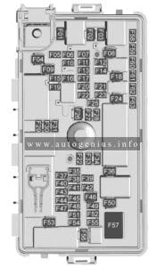
Ford Bronco Sport (2021 - 2023) - fuses and relay box diagram - passenger compartment
Ford Bronco Sport (2021 – 2023) – fuses and relay box diagram – passenger compartment


Assignment of the fuses in the Passenger Compartment Fuse Box

Amp. Protected Component
1 5A Not used.
2 5A Not used.
3 10A Not used.
4 10A Ignition switch.
Steering column lock.
5 20A Lock.
Unlock.
6 10A DC-AC inverter.
7 30A Passenger door module.
8 5A Parking assist control module.
9 5A Auto-dimming interior mirror.
Lane keeping system.
Passenger airbag deactivation indicator.
10 10A Extended power module.
11 5A Telematics control unit module.
12 5A Keyless keypad switch.
13 15A Driver door unlock.
14 30A Driver door module.
15 15A Not used (spare).
16 15A Not used (spare).
17 15A SYNC.
Receiver transceiver module.
Integrated control panel.
18 7.5A Wireless accessory charging module.
All terrain control module.
19 7.5A Not used (spare).
20 10A Not used (spare).
21 7.5A Not used (spare).
22 7.5A Not used (spare).
23 20A Not used (spare).
24 20A Not used (spare).
25 30A Not used (spare).


Engine Compartment Fuse Box

Fuse Box Diagrams

Ford Bronco Sport (2021 - 2023) - fuses and relay box diagram - engine compartment
Ford Bronco Sport (2021 – 2023) – fuses and relay box diagram – engine compartment


Assignment of the fuses in the Passenger Compartment Fuse Box

Amp. Protected Component
1 30A Aftermarket auxiliary lighting.
2 Not used.
3 10A 2021: Windshield heated washer jets.
4 60A Supplemental heater.
5 40A Supplemental heater.
6 40A Supplemental heater.
7 20A Heated wiper park.
8 Not used.
9 60A Power inverter.
10 30A Starter motor.
11 15A Powertrain control module.
12 15A Powertrain control module.
13 15A Powertrain control module.
14 15A Powertrain control module.
15 Not used.
16 Not used.
17 Not used.
18 10A Powertrain control module.
19 10A Anti-lock brake system module.
20 10A Data link connector.
21 5A Headlamp switch.
22 20A Amplifier.
23 Not used.
24 Not used.
25 25A Left-hand enhanced headlamps.
26 25A Right-hand enhanced headlamps.
27 Not used.
28 Not used.
29 Not used.
30 10A 2021: Electronic stability control.
31 5A Electronic power assist steering.
32 30A Body control module.
33 10A Front parking aid camera.
Rear view camera.
Blind spot information system.
Gear shift actuator.
34 Not used.
35 15A Heated steering wheel.
36 Not used.
37 20A Horn.
38 40A Blower motor.
39 Not used.
40 10A Brake on-off switch.
41 20A Amplifier.
42 30A Driver power seat.
43 40A Anti-lock brake system valves.
44 40A Trailer tow module.
45 30A Passenger power seat.
46 Not used.
47 20A Heated seats.
48 Not used.
49 60A Anti-lock brake system pump.
50 60A Cooling fan.
51 30A Moonroof.
52 5A USB smart charger.
53 Not used.
54 Not used.
55 Not used.
56 10A A/C clutch.
57 5A Flood light.
58 Not used.
59 40A Body control module.
60 5A USB smart charger.
61 20A Auxiliary power point.
62 Not used.
63 Not used.
64 Not used.
65 Not used.
66 Not used.
67 Not used.
68 Not used.
69 15A Port fuel injectors.
70 20A Auxiliary power point.
71 20A Auxiliary power point.
72 20A Rear window wiper.
73 Not used.
74 30A Windshield wiper motor.
75 10A Heated exterior mirrors.
76 30A Heated rear window.
77 Not used.
78 15A Liftgate window release.
79 Not used.
80 20A Fuel pump.
81 10A Rear window washer pump.
82 40A Power inverter.
83 Not used.
84 40A Driveline control module.
85 5A Rain sensor.
86 Not used.
87 Not used.
88 Not used.


WARNING: Terminal and harness assignments for individual connectors will vary depending on vehicle equipment level, model, and market.
Ford Transit Connect (2019 – 2022) – fuse and relay box diagram

Ford Transit Connect (2019 – 2022) – fuse and relay box diagram

Year of production: 2019, 2020, 2021, 2022


This article covers the facelifted second-generation Ford Transit Connect, produced from 2019 to 2022. It includes fuse box diagrams for the 2019, 2020, 2021, and 2022 models, provides information on the location of the fuse panels within the vehicle, and details the function and layout of each fuse and relay.


Passenger compartment fuse box

Fuse box location

It is located in the passenger compartment below the glove box.


Fuse box diagram

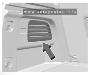
Ford Transit Connect (2019 - 2022) - fuses and relay box diagram - passenger compartment
Ford Transit Connect (2019 – 2022) – fuses and relay box diagram – passenger compartment


Assignment of the fuses in the passenger compartment

Amp Rating Description
1 5A Restraints control module
2 5A In-vehicle temperature and humidity sensor
Rear blower motor
3 10A Parking assist control module
4 10A Ignition switch
Push button ignition switch
5 20A Central locking system
6 10A Direct current inverter
Driver door lock
Power exterior mirror switch
7 30A Driver door control
9 5A Auto-dimming interior mirror
Front parking aid camera
Passenger airbag deactivation indicator
10 10A Restraints control module
11 5A Telematics control unit module
12 5A Anti-theft alarm
13 15A Unlock
14 30A Passenger door control
15 10A Battery energy control module
17 15A Voice control
Information and entertainment display
Compact disc player
18 7.5A Wireless accessory charging module
19 7.5A Battery back-up sounder
20 10A Security horn
21 7.5A Climate control
22 7.5A Data link connector
Instrument cluster
23 20A Audio unit
25 30A Power windows

Engine compartment fuse box

Fuse box diagram

Ford Transit Connect (2019 - 2022) - fuses and relay box diagram - engine compartment
Ford Transit Connect (2019 – 2022) – fuses and relay box diagram – engine compartment


Assignment of the fuses in the engine compartment

Amp Rating Description
4 20A / 25A Cooling fan (Gasoline, 20A)
Water-in-fuel sensor (Diesel, 25A)
6 15A Windshield wipers
7 15A Windshield wipers
8 15A Rear window washer pump
9 10A Rear cargo door unlock
Liftgate unlock
10 20A Rear floor console auxiliary power point
11 20A Floor console auxiliary power point
12 5A Rain sensor
13 20A Rear window wiper
16 20A Sun shade
17 15A Steering column lock
19 10A Left-hand door unlock
20 20A Auxiliary power point
21 20A Rear auxiliary power points
22 5A USB port
25 20A Dosing control unit (diesel)
26 20A Dosing control unit (diesel)
27 15A Dosing control unit (diesel)
28 15A Transmission control module (diesel)
29 50A Glow plugs (diesel)
31 20A Right-hand low beam
32 10A Stoplamp switch
33 30A Driver power seat
34 40A Direct current/alternating current inverter
35 50A Glow plugs (diesel)
37 10A Modified vehicle connection
38 10A Data link connector
39 20A Fuel-operated parking heater
40 40A Rear blower motor
41 60A Anti-lock brake system
Electronic stability control
42 40A Modified vehicle connection
43 15A Status lamp – taxi
44 5A Headlamps
45 30A Right-hand rear door module
46 40A Body control module
47 40A Trailer tow module
48 20A Heated seats
49 20A Left-hand low beam
50 5A Sun shade
51 30A Anti-lock brake system
Electronic stability control
52 40A Right-hand heated windshield element
53 10A Air conditioning clutch
55 5A Transmission control module
56 5A Anti-lock brake system
Electronic stability control
57 10A Modified vehicle connection
58 10A Powertrain control module
60 20A Modified vehicle connection
61 15A Blind spot information system
Front parking aid camera
Rear view camera
62 20A Body control module
63 10A Modified vehicle connection
64 5A Headlamp leveling
65 5A Electronic power assist steering
66 5A Dosing control unit (diesel)
Glow plugs (diesel)
Powetrain control module (diesel)
67 20A Powertrain control module
68 20A Powertrain control module
69 15A Powertrain control module
70 20A Powertrain control module
73 5A Mass air flow and intake air temperature sensor
79 10A Heated exterior mirrors
80 5A Modified vehicle connection
81 20A Horn
82 40A Left-hand heated windshield element
83 5A Windshield heated washer jets
84 60A Cooling fan
85 30A Fuel pump
86 20A Starter motor
87 60A Glow plug module (diesel)
89 40A Blower motor
90 25A Heated rear window

WARNING: Terminal and harness assignments for individual connectors will vary depending on vehicle equipment level, model, and market.