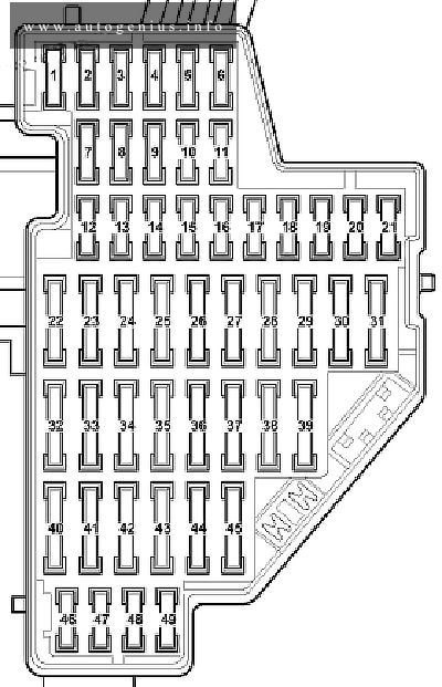
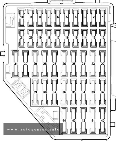
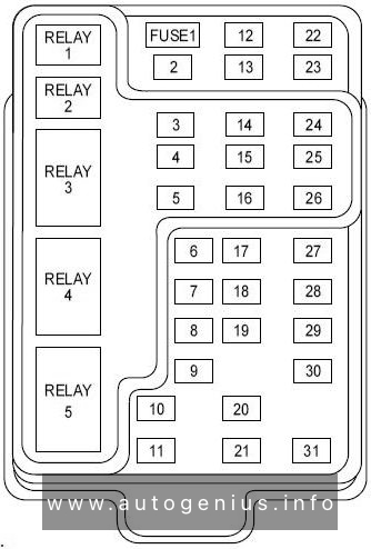
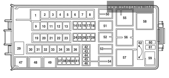
Volkswagen Karmann GHIA (1954 – 1979 all models) – fuse and relay box diagram

VW Karmann GHIA (1954 – 1979) – fuse and relay box diagram


Fuses box diagram (typical relay location od the fuse box)

Volkswagen Beetle (1954 - 1979) - fuse box
Volkswagen Karmann GHIA (1954 – 1979) – fuse box diagram


Fuse/relay Description
1 Low beam
2 Open
3 Turn signal/emergency flasher
4 Open
5 Buzzer

WARNING: Terminal and harness assignments for individual connectors will vary depending on vehicle equipment level, model, and market.

Volkswagen Beetle (1954 – 1979) – fuse and relay box diagram

VW Beetle (1954 – 1979) – fuse and relay box diagram

Year of production: 1954, 1955, 1956, 1957, 1958, 1959, 1960, 1961, 1962, 1963, 1964, 1965, 1966, 1967, 1968, 1969, 1970, 1971, 1972, 1973, 1974, 1975, 1976, 1977, 1978, 1979


The classic compact car Volkswagen Beetle was produced from 1938 to 2003. In this article, you will find fuse box diagrams for the Volkswagen Beetle models from 1954 through 1979, get information about the location of the fuse panels inside the vehicle, and learn about the assignment of each fuse (fuse layout) and relay.

Fuse box diagram

Volkswagen Beetle (1954 - 1979) - fuse and relay box diagram
Volkswagen Beetle (1954 – 1979) – fuse and relay box diagram


Assignment of the fuses in the fuse box

Fuse/relay Description
1 Low beam
2 Open
3 Turn signal/emergency flasher
4 Open
5 Buzzer

WARNING: Terminal and harness assignments for individual connectors will vary depending on vehicle equipment level, model, and market.

Volkswagen Passat (B6; 2005 – 2010) – fuse and relay box diagram

Volkswagen Passat (B6; 2005 – 2010) – fuse and relay box diagram

Year of production: 2005, 2006, 2007, 2008, 2009, 2010


This article covers the fifth-generation Volkswagen Passat (B6/3C), manufactured between 2005 and 2010. It provides fuse box diagrams for the 2005–2010 Passat models, explains where the fuse panels are located inside the vehicle, and details the function and layout of each fuse and relay.


Passenger compartment

Fuse box location

The fuse box is located on the left side edge of the instrument panel.


Fuse box diagram

Volkswagen Passat (B6; 2005 - 2010) - fuse box diagram - passenger compartment (left-side)
Volkswagen Passat (B6; 2005 – 2010) – fuse box diagram – passenger compartment (left-side)


Assignment of the fuses in the left-side of the dash panel

Amp rating Component
F1 10A Datalink connector (DLC)
F2 5A Anti-lock brake system (ABS)
F3 5A Power steering
F4 5A Brake pedal position (BPP)switch
F5 10A LH gas discharge head lamp, head lamp level control module, head lamp adjustment motor, left or single, head lamp adjustment motor, right
F6 5A Trailer control module
F7 5A Data bus connection, engine management, instrumentation control module
F8 5A Garage door opener, interior rearview mirror, rear window blind
F9 5A Four-wheel drive control module
F10 5A Engine management
F11 5A Accident data recorder button, taximeter
F12 10A Door function control module, driver
F13 10A Datalink connector (DLC), light switch
F14 5A Steering column function control module
F15 5A Multifunction control module 1
F16 10A Ignition system
F17 10A Alarm system, auxiliary heater, wind screen wiper rain sensor
F18
F19
F20
F21
F22 5A/10A Engine management
F23 10A Engine management
F24 5A/20A Transmission control module(TCM), reverse gear position switch
F25 10A Engine management
F26 10A Rear window blind
F27 5A Heater/air conditioning (AC)
F28
F29 20A Trailer control module
F30 15A Trailer control module
F31 25A Trailer control module
F32 30A Multifunction control modulel
F33 20A Sunroof
F34 15A Engine management
F35 30A Head lamp washers
F36 20A Auxiliary heater
F37 30A Heated seats
F38
F39 40A Heater/air conditioning (AC)
F40 5A Fog lamps
F41 40A Heater/air conditioning{AC)
F42 15A Windscreen washers, rear screen wiper motor
F43 20A Auxiliary heater
F44 20A Auxiliary heater
F45 25A Auxiliary power sockets
F46 5A Two-way radio (police), crash control module(taxi/police), ignition switch circuits, tachograph
F47 15A Alarm system (taxi), auxiliary power sockets (glove box) – taxi, auxiliary power sockets(luggage compartmenty-taxi, auxiliary power sockets(two-way radio)- police, interior lamps, luggage compartment lamp
F48 20A Auxiliary power sockets (police)
F49


Fuse box location

It is located on the right side edge of the instrument panel.


Fuse box diagram

Volkswagen Passat (B6; 2005 - 2010) - fuse box diagram - passenger compartment (right-side)
Volkswagen Passat (B6; 2005 – 2010) – fuse box diagram – passenger compartment (right-side)


Assignment of the fuses in the right-side of the dash panel

Amp rating Component
F1
F2 5A Ant Mock brake system (ABS), parking brake control module
F3 5A Parking aid control module, navigation system
F4 5A Cruise control
F5 10A RH gas discharge headlamp
F6 5A Transmission mode selection switch
F7 5A Headlamp level control module
F8 5A Engine management
F9 10A Supplementary restraint system (SRS)
F10 5A Engine management (BLF/BLR/B LY/AXX/B PY/B LX/BVX/BVY/BVZ/BWA)
F12 10A Door function control module, left front
F13 10A Parking aid control module
F14 10A Assisted door closing control module relay
F15 5A Heater/air conditioning (AC)
F16 5A Transmission mode selection switch
F17 10A Anti-lock brake system (ABS), parking brake control module
F18
F19
F20
F21
F22 30A Accessories connector
F23 30A Door function control module, left rear, door function control module, right rear
F24 30A Assisted door closing control module, left rear
F25 30A Assisted door closing control module, right rear
F26
F27 25A Heated seats
F28 15A Engine management
F29 30A Door function control module, driver, door function control module, left front
F30 20A Parking brake control module
F31 20A Parking brake control module
F32
F33 20A Accessories connector
F34 15A Engine management (AXX/BLF/BLR/BLX/BLY/BPY/BVX/BVY/BVZ/BWA)
F35 20A Cigarette lighter
F36
F37
F38
F39 10A Heater/air conditioning (AC), heated seats, heated wind screen waterjets, split charge relay
F40 5A Crash control module (taxi/police)
F41 15A Alarm system (taxi), auxiliary power sockets (glove box) – taxi, auxiliary power sockets(luggage compartment)-taxi, interior lamps-taxi, roof sign lamp-taxi, taximeter
F42 20A Auxiliary power sockets(glove box}-taxi
F43 5A Alarm system (taxi), auxiliary power sockets (police), auxiliary power sockets (glove box) – taxi, auxiliary power sockets (luggage com partment) -taxi
F44 20A Alarm system (taxi), auxiliary power sockets- taxi, auxiliary power sockets (police)


Engine compartment

Fuse box diagram (type 1)

Volkswagen Passat (B6; 2005 - 2010) - fuse box diagram - engine compartment (type 1)
Volkswagen Passat (B6; 2005 – 2010) – fuse box diagram – engine compartment (type 1)


Assignment of the fuses in the Engine compartment, type 1

Amp Rating Component
A1 Ignition main circuits relay
A2
A3
A4
F1 5A/15A Transmission control module (TCM)
F2 30A Anti-lock brake system (ABS)
F3 20A Multifunction control module 2
F4 5A Multifunction control module 1
F5 20A Horn
F6
F7
F8
F9
F10
F11
F12
F13
F14
F15
F16 15A Steering column function control module
F17 10A Instrumentation control module
F18 30A Audio unit output amplifier
F19 15A Audio system, navigation system
F20 5A Aerial module, telephone
F21
F22 7,5A Telematics control module
F23 10A Engine management
F24 10A CAN data bus gateway control module
F25
F26 10A Engine management
F27 10A Engine management-Diesel
F28 25A/30A Engine management
F29 10A/15A Engine management
F30 20A Auxiliary heater control module
F31 30A Windscreen wipers
F32
F33
F34
F35
F36
F37
F38 10A Engine coolant blower motor control module, engine management
F39 10A Engine management
F40 10A/15A Engine management
F41
F42
F43
F44
F45
F46
F47 40A LH headlamp, LH tail lamp, multifunction control module 1, RH front side lamp, RH tail lamp
F48 40A LH side lamp, LH tail lamp, multifunction control module 1, RH headlamp, RH tail lamp
F49 50A Multifunction control module 1
F50 60A Split charge relay
F51
F52 60A Heated rear window
F53 50A Fascia fuse box/relay plate 1 (F40-F42), fascia fuse box/relayplate2(F39), multifunction control module 1
F54 50A Glow plug control module


Fuse box diagram (type 2)

Volkswagen Passat (B6; 2005 - 2010) - fuse box diagram - engine compartment (type 2)
Volkswagen Passat (B6; 2005 – 2010) – fuse box diagram – engine compartment (type 2)


Assignment of the fuses in the Engine compartment, type 2

Amp Rating Component
A1 Secondary air injection (AIR) pump relay
A2 Ignition main circuits relay
F1 7,5A Telematics control module
F2 30A Anti-lock brake system (ABS)
F3 20A Multifunction control module 1
F4 20A Multifunction control module 2
F5 5A Multifunction control module 1
F6 5A/15A Transmission control module (TCM)
F7 15A Audio system, navigation system
F8
F9 15A Steering column function control module
F10 20A Engine management
F11 5A Instrumentation control module
F12 5A Telephone control module
F13 10A Engine management
F14 30A Engine management
F15 10A CAN data bus gateway control module
F16 10A/15A Engine management
F17
F18
F19 30A Audio unit output amplifier
F20 5A/15A Clutch position potentiometer engine management
F21 20A Auxiliary heater control module
F22 30A Windscreen wipers
F23 10A Engine coolant blower motor control module, engine management
F24 10A/15A Engine management
F25 40A Multifunction control module 1
F26 40A Multifunction control module 1
F27 60A Heated rear window
F28 40A Engine management-petrol
F29 50A Multifunction control module 1
F30 50A Multifunction control module 1


Pre-Fuse box

Volkswagen Passat (B6; 2005 - 2010) - fuse box diagram - pre-fuse
Volkswagen Passat (B6; 2005 – 2010) – fuse box diagram – pre-fuse


Assignment of the fuses in the pre-fuse box

Amp Rating Component
SA1 150A Alternator
SA2 80A Power steering
SA3 50A/80A Engine coolant blower motor control module
SA4 100A Fascia fuse box/relay plate 1 (F32-F37), fascia fuse box/relay plate 2 (F32-F37), fascia fuse box/relay plate 3 (F44/F46)
SA5 80A Fascia fuse box/relay plate 2 (F22-F27)
SA6 50A Fascia fuse box/relay plate 1 (F12-F17/F29-F31)
SA7 60A Split charge relay
SA8 40A Anti-lock brake system (ABS)


WARNING: Terminal and harness assignments for individual connectors will vary depending on vehicle equipment level, model, and market.

Volkswagen Golf 3 (mk3; VR6 AAA) – fuse and relay box diagram

VW Golf 3 (mk3; VR6 AAA) – fuse and relay box diagram


Fuse box

(From left to right)

Number Component Ampere rating [A]
1 Dipped beam left,
headlight range control left
10
2 Dipped beam right,
head light range control right
10
3 Instrument and number plate
lighting
10
4 Rear wiper, slid ing/tilting roof 15
5 Windscreen wiper, windscreen
and rear window washer,
elec. heated windscreen washer
jets
15
6 Blower, air conditioner 30
7 Tail and side light ri ht 10
8 Tail and side light left 10
9 Rear window heating, mirror
heating
20
10 Fog lights, rear fog light 15
11 Main beam left, main beam
warning lamp
10
12 Main beam right 10
13 Horn, radiator fan (run-on) 10
14 Reversing lights, electric outside
mirrors, seat heating,
elec. windows, air conditioner
cruise control system
15
15 Engine electronics, coolant
circulat ion run-on pump,
(six cylinder engine)
10
16 Warning lamps, glove box light,
cassette storage box light,
15
17 Turn signals 10
18 Electric fuel pump, Lambda probe 20
19 Radiator fan, air conditioner 30
20 Brake lights, cruise control
system (trigger contacts on
brake and clutch pedals)
10
21 Interior and luggage compartment
lights, clock, cigarette lighter,
central locking, multi-function
indicator
15
22 Radio 10


Additional fuses

(in separate holders)

above the relays
Fuse for ABS motor relay 30
Fuse for ABS main relay 30
Fuse for normal air conditioner 10
Fuse for fresh air blower on
Climatronic
30
Fuse for C1imatronic 5
Automatic fuse for electric windows 20
Trailer permanent + 15
in the engine compartment on the bulkhead
above the brake servo
Diesel glow plugs 50

WARNING: Terminal and harness assignments for individual connectors will vary depending on vehicle equipment level, model, and market.

Volkswagen Golf 1 (mk1; 1981 – 1984) – fuse and relay box diagram (U.S – built models with fuel injectors)

VW Golf 1 (mk1; 1981 – 1984) – fuse and relay box diagram

(U.S – built models with fuel injectors)

Year of production: 1981, 1982, 1983, 1984


The 1st generation Volkswagen Golf compact car was produced (U.S – built) in 1975, 1976, 1977, 1978, 1979, 1980, 1981, 1982, 1983 and 1984 with gasoline and diesel engines. Delivered worldwide in various body styles: convertible, sedan, station wagon and hatchback. In this article you will find a designation of the fuse and relay boxes diagram of the 1st generation Volkswagen Golf.

Fuse box diagram

Volkswagen Golf 1 (mk1; 1981 - 1984)- fuse and relay box diagram
Volkswagen Golf 1 (mk1; 1981 – 1984)- fuse and relay box diagram


Assignment of the fuses and in the fuse box diagram

Fuse Ampere rating [A] Part Number Circuit Power source
1 30 N17131.9 Radiator fan motor Terminal 30 — battery
2 15 N17131.6 Parking lights Terminal 30 — battery
3 20 N17131.7 Horn Terminal 30 — battery
5 4 N17131.2 Dashboard and console illuminating lights Headlight switch
6 30 N17131.9 Fuel pump relay Terminal 30 — battery
9 10 N17131.5 Rear window wiper motor Terminal 15 — ignition switch
10 15 N17131.6 Turn signal Terminal 15 — ignition switch
11 5 N17131.3 Radio Terminal 15 — ignition switch
12 10 N17131.5 Back-up lights, cruise control Terminal 15 — ignition switch
19 25 N17131.8 Heater motor Terminal X – load reduction relay
20 25 N17131.8 Rear window deffoger Terminal X – load reduction relay
21 20 N17131.7 Windshield wiper motor Terminal X – load reduction relay
24 15 N17131.6 Brake lights and emergency flasher Terminal 30 — battery
25 15 N17131.6 Dome, clock and glove compartment lights Terminal 30 — battery
26 10 N17131.5 Cigarette lighter Terminal 30 — battery
27 4 N17131.2 Horn relay Terminal 30 — battery

Auxiliary relays


Assignment of the relay and in the fuse box diagram

Relay number Model years Component
1 1981 – 1983 Upshift control
1984 Fuel pump
2 1981 – 1983 Rear window wiper/washer
1984 Oxygen sensor control
3 1981 – 1982 Hot-start pilse
1983 Oxygen sensor control
1984 Rear window wiper/washer
4 1981 – 1982 Oxygen sensor control
1984 Upshift control
5 1983 – 1984 Hot-start pulse
6 1981 – 1983 Fuel pump
1984 Oil pressure warrning system

WARNING: Terminal and harness assignments for individual connectors will vary depending on vehicle equipment level, model, and market.

Volkswagen Jetta (MK1; 1979 – 1984) – fuse and relay box diagram

VW Jetta (MK1; 1979 – 1984) – fuse and relay box diagram


Year of production: 1979, 1980, 1981, 1982, 1983, 1984


The  Volkswagen Jetta was a compact family car produced from 1979 to 1984. In this article, you will find  fuse box diagrams for Volkswagen Jetta mk1 models from 1979 to 1984, along with details on the fuse panel locations inside the vehicle and the specific functions of each fuse (fuse layout) and relay.


Fuse box diagram

Volkswagen Jetta (mk1, 1979 - 1984)- fuse and relay box diagram
Volkswagen Jetta (mk1, 1979 – 1984)- fuse and relay box diagram


Assignment of the fuses and relays in the fuse box

Fuse Description Ampere rating [A]
1 Headlight, Low Beam, Left 10
2 Headlight, Low Beam, Right 10
3 License Plate Lights 10
4 Rear Window Wiper And Washer System 15
5 Windshield Wiper/Washer 15
6 Fresh Air Blower, A/C 20
7 Tail Lights, Right 10
8 Tail Lights, Left 10
9 Rear Window Defogger 20
10 Fog Lights 15
11 Headlight, High Beam, Left 10
12 Headlight, High Beam, Right 10
13 Horn 10
14 Back-Up Lights 10
15 Engine Electronics 10
16 Power Sunroof, Front Map/Reading Light 15
17 Emergency Flashers 10
18 uel Pump (FP), Heated Oxygen Sensor (HO2S) Control Module 20
19 Coolant Fan, A/C Relay 30
20 Brake Lights 10
21 Interior Lights, Clock, Luggage Compartment light 15
22 Cigarette Lighter, Radio, Luggage Compartment Release 10

Fuse/Relay Panel – Rear Connections (Volkswagen Part Number 357 937 039)

Volkswagen Jetta (mk1, 1979 - 1984)- fuse and relay box diagram - rear connection
Volkswagen Jetta (mk1, 1979 – 1984)- fuse and relay box diagram – rear connection


Assignment of the fuses and relays in the rear connections

Connection and plugs Description
A1 Yellow 8 pin Headlight wiring harness
A2 Yellow 8 pin Headlight wiring harness
B Green 6 pin Headlight washer wiring harness
C Yellow 8 pin Headlight or wiper motor wiring harness
D Green 12 pin Miscellaneous equipment, varies (A/C, A/T, heated seats, seat belt warning, etc.)
E Green 5 pin Instrument or brake light wiring harness
F White 10 pin Engine compartment/engine management, wiring harness, right side (position 10 open)
G1 White 12 pin Engine compartment/engine management, right side
G2 White 12 pin Engine compartment/engine management, right side (position 12 open)
H1 Red 10 pin Steering column switch wiring harness
H2 Red 8 pin Steering column switch wiring harness (position 8 open)
J Red 10 pin Steering column switch wiring harness
K Black 12 pin Rear wiring harness
L Black 8 pin Rear/Parking brake wiring harness (position 8 open)
M Black 6 pin Rear/fuel tank wiring harness
N Green 6 pin Air conditioning wiring harness
P Blue 10 pin Rear window defroster/fog light wiring harness
Q Blue 6 pin Fresh air blower fan wiring harness (position 10 open)
R Blue 10 pin Light switch wiring harness
S White 5 pin Engine compartment/wiper motor wiring harness, right side
T Green 2 pin Individual circuits
U1 Blue 14 pin Instrument cluster wiring harness
U2 Blue 14 pin Instrument cluster wiring harness
V Green 4 pin Steering column switch Multi-function indicator wiring harness
W Green 6 pin Miscellaneous optional equipment, varies with vehicle type
X Green 8 Warning lamp wiring harness
Y n/a 1 pin 4 single point connectors for terminal 30 circuit (some may be bridged with red connector)
Z1 n/a 1 pin Single point connector
Z2 n/a 1 pin Single point connector for terminal 31 circuit
30 n/a 1 pin Single point connector for terminal 30 circuit (may be bridged to 30B with red connector)
30B n/a 1 pin Single point connector for terminal 30 circuit (may be bridged to 30 with red connector)


WARNING: Terminal and harness assignments for individual connectors will vary depending on vehicle equipment level, model, and market.

Lincoln Navigator (UN173; 2000 – 2002) – fuse and relay  box diagram

Lincoln Navigator (UN173; 2000 – 2002) – fuse and relay  box diagram

Year of production: 2000, 2001, 2002


This article covers the first-generation Lincoln Navigator, manufactured between 1998 and 2002. It includes fuse box diagrams for the 2000, 2001 and 2002 models, provides details on the locations of the fuse panels within the vehicle, and explains the function and layout of each fuse and relay.

Passenger compartment fuse panel

Fuse box location

The fuse panel is located below and to the left of the steering wheel behind the cover.


Fuse box diagram

Lincoln Navigator (UN173; 2000 - 2002) - fuse and relay box diagram - passenger compartment
Lincoln Navigator (UN173; 2000 – 2002) – fuse and relay box diagram – passenger compartment


Assignment of the fuses and relays in the passenger compartment (2000 – 2002)

No.
A
Circuit Protected
1 25A Audio
2 5A Clock, Overhead Trip Computer, Electronic Automatic Temperature Control (EATC), Powertrain Control Module (PCM), Cluster, Navigation
3 20A Cigar Lighter, OBD-II Scan Tool Connector
4 7.5A Remote Entry Module, Mirrors, Memory Module, Adjustable Pedals, Drivers Seat, Power Fold Mirrors
5 15A Speed Control Module, Reverse Lamp, Daytime Running Lamp Relay, Reverse Sensing System, Autolock, E/C Mirror, Navigation
6 5A Cluster, Overhead Trip Computer, Compass, Steering Sensor, Brake Shift Interlock Solenoid, Air Suspension Module, GEM Module, Heated Mirror, Rear Defroster, Reverse Sensing System, Automatic Park Brake Release
7 5A Aux A/C Blower Relay, Console Blower
8 5A Remote Entry Module, Cell Phone, Clock, GEM Module, Navigation
9 Not Used
10 Not Used
11 30A Front Washer Pump Relay, Wiper Run/Park Relay, Wiper Ili/LO Relay, Windshield Wiper Motor, Rear Washer Pump Relay
12 15A Air Suspension Switch
13 20A Stop Lamp Switch (Lamps), Turn/Hazard Flasher, Speed Control Module
14 15A Rear Wipers, Running Board Lamps, Battery Saver Relay, Interior Lamp Relay, Accessory Delay Relay (Power Windows, Moonroof, Flip Windows, Audio), Homelink
15 5A Stop Lamp Switch, (Speed Control, Brake Shift Interlock, ABS, PCM Module Inputs), GEM Module, Autolock, Air Suspension Module
16 20A Headlamps (Hi Beams), Cluster (Hi Beam Indicator)
17 10A Heated Mirrors/Rear Window Defroster Indicator
18 5A Instrument Illumination (Dimmer Switch Power), Clock (Dimmer), Navigation Screen
19 Not Used
20 5A Audio, Air Suspension Module, Memory Module, GEM Module
21 15A Starter Relay, Fuse 20, Digital Transmission Range Selector
22 10A Air Bag Module, EATC, EATC Blower Relay, Feeds Fuse 7
23 10A Electrochromic Mirror, Aux A/C, Heated Seats, Trailer Tow Battery Charge, Tum/Hazard Flasher, Console Blower Door Actuator, 4×4 Clutch Relay, 4 Wheel Anti-Lock Brake System (4WABS) Module
24 10A 2000-2001: Not Used
2002: EATC Module, EATC Blower/Flasher Relay, Climate Control Selector Switch, Feeds fuse 7
25 Not Used
26 10A Right Side Low Beam Headlamp
27 5A Foglamp Relay and Foglamp Indicator
28 10A Left Side Low Beam Headlamp
29 5A Autolamp Module, Transmission Overdrive Control Switch
30 30A Passive Anti Theft Transceiver, Cluster, Ignition Coils, Powertrain Control Module Relay
31 10A Rear Integrated Control Panel (Audio), CD Player, Cell Phone
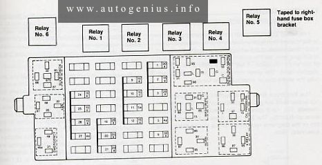
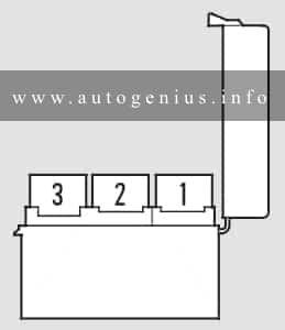
Relay 1 Interior Lamp Relay
Relay 2 Battery Saver Relay
Relay 3 Rear Window Defroster Relay
Relay 4 One Touch Down Window Relay
Relay 5 ACC Delay Relay

Engine Compartment Fuse Box

Fuse box location

The power distribution box is located in the engine compartment (on the driver’s side).


Fuse box diagram

Lincoln Navigator (UN173; 2000 - 2002) - fuse and relay box diagram - engine compartment
Lincoln Navigator (UN173; 2000 – 2002) – fuse and relay box diagram – engine compartment


Assignment of the fuses and relays in the engine compartment (2000 – 2002)

Amp Rating Description
1 20A Power Point
2 30A Powertrain Control Module
3 30A Headlamps/Autolamps
4 20A Console Powerpoint
5 20A Trailer Tow Backup/Park Lamps
6 15A Parklamps/Autolamps, Feeds Passenger Compartment Fuse 18
7 20A Horn
8 30A Power Door Locks
9 15A Daytime Running Lamps (DRL), Fog Lamps
10 20A Fuel Pump
11 20 A Alternator Field
12 10A Rear Wipers
13 15A A/C Clutch
14 Not Used
15 10A Running Board Lamps
16 Not Used
17 10A Delayed Accessory (Audio, Flip Windows)
18 15A Powertrain Control Module, Fuel Injectors, Fuel Pump, Mass Air Flow Sensor
19 10A Trailer Tow Stop and Right Turn Lamp
20 10A Trailer Tow Stop and Left Turn Lamp
21 Not Used
22 Not Used
23 15A HEGO Sensors, Canister Vent, Transmission, CMS Sensor
24 Not Used
101 30A Trailer Tow Battery Charge
102 50A Four Wheel Antilock Brake Module
103 50A Junction Box Battery Feed
104 30A 4×4 Shift Motor & Clutch
105 40A Climate Control Front Blower
106 Not Used
107 30A Passenger Power Seat, Passenger Seat Lumbar
108 30A Trailer Tow Electric Brake
109 50A Air Suspension Compressor
110 30A Heated Seats/CCS
111 40A Ignition Switch Battery Feed (Run and Start Circuits)
112 30A Memory (Drivers Seat, Adjustable Pedals, Mirrors), Drivers Seat Lumbar
113 40A Ignition Switch Battery Feed (Run and Accessory Circuits)
114 30A Climate Control Auxilary Blower
115 Not Used
116 40A Rear Window Defroster, Heated Mirrors
117 Not Used
118 Not Used
201 Trailer Tow Park Lamp Relay
202 Front Wiper Run/Park Relay
203 Trailer Tow Backup Lamp Relay
204 A/C Clutch Relay
205 Rear Wiper Down
206 Fog Lamp Relay
207 Front Washer Pump Relay
208 Rear Washer Pump Relay
209 Rear Wiper Up Relay
301 Fuel Pump Relay
302 Trailer Tow Battery Charge Relay
303 Front Wiper Hi/Lo Relay
304 Powertrain Control Module Relay
401 Not Used
501 Powertrain Control Module Diode
502 A/C Clutch Diode
503 Automatic Park Brake Release Diode
601 30A Delayed Accessory (Power Windows, Flip Windows, Radio, Moonroof)
602 Not Used
502 A/C Clutch Diode
503 Not Used
601 30A Delayed Accessory (Power Windows, Flip Windows, Radio)
602 Not Used


WARNING: Terminal and harness assignments for individual connectors will vary depending on vehicle equipment level, model, and market.

Acura CL (YA4; 2003) – fuse and relay box diagram

Acura CL (YA4; 2003) – fuse and relay box diagram

Year of production: 2003


This article covers the second-generation  Acura CL, produced from 1997 to 2003. It includes fuse box diagrams for the 2003 models, provides details on the location of the fuse panels inside the vehicle, and explains the function and layout of each fuse.


Engine compartment

Fuse box diagram

Acura CL (YA4; 2003)- fuse and relay box diagram - engine compartment
Acura CL (YA4; 2003)- fuse and relay box diagram – engine compartment


Assignment of the fuses in the engine compartment

Fuse Ampere rating [A] Circuits Protected
1*1  20 Condenser Fan
1*2 30 Condenser Fan
2 7,5 MG Clutch
3 60 IG1 Main
4 40 Rear Window Defogger
5 40 Heater Motor
6*1 20 TCS
6*2 40 VSA
6*3 Not used
7 40 Power Seat
8 40 Power Window Motor
9 40 Back Up, ACC
10 15 Spare Fuse
11 10 Spare Fuse
12 7,5 Spare Fuse
13*1,*3 20 Cooling Fan
13*2 30 Cooling Fan
14 120 Battery
15 30 Spare Fuse
16 20 Spare Fuse
17 15 Hazard
18 30 ABS Motor
19 15 ACG S
20 20 Stop
21 20 ABS F/S Relay
22 20 Right Headlight
23 Not used
24 20 Left Headlight

*1 – Premium model

*2 – Type-S with A/T

*3 – Type-S with M/T


Passenger compartment

Fuse box diagram (driver’s side)

Acura CL (YA4; 2003)- fuse and relay box diagram - passenger compartment (driver's side)
Acura CL (YA4; 2003)- fuse and relay box diagram – passenger compartment (driver’s side)


Assignment of the fuses in the passenger compartment (driver’s side)

Fuse Ampere rating [A] Circuits Protected
1 15 Fuel Pump
2 10 Main SRS
3 7,5 Heater Control, A/C Clutch Relay, Cooling Fan Relay
4 7,5 Mirror, Heated Seat, Heated Mirror
5 7,5 Daytime Running Lights*
6 15 ECU (PCM), Cruise Control, VSA
7 7,5 Side SRS
8 7,5 ACC Relay, Navigation
9 7,5 Instrument Panel, Back-up Lights, Memory Seat
10 7,5 Turn Signals
11 15 IG Coil
12 30 Wiper, Washer
13 7,5 Starter Signal

*-On Canadian models


Fuse box diagram (passenger’s side)

Acura CL (YA4; 2003)- fuse and relay box diagram - passenger compartment (passenger's side)
Acura CL (YA4; 2003)- fuse and relay box diagram – passenger compartment (passenger’s side)


Assignment of the fuses in the passenger compartment (passenger’s side)

Fuse Ampere rating [A] Circuits protected
1 30 Left Power Window
2 20 Driver’s Power Seat Reclining, Memory Seat
3 20 Heated Seat
4 20 Driver’s Power Seat Sliding, Memory Seat
5 20 Passenger’s Power Seat Sliding
6 20 Passenger’s Power Seat Reclining
7 30 Moonroof Motor
8 20 Right Power Window
9 20 Radio, Power Outlet
10 10 Navigation System, Daytime Running Lights*1, OnStar*2
11 7,5 Interior Light, Seat Memory, HomeLink
12 20 Power Door Locks
13 15 Clock, Back Up, Small Light
14 7,5 ABS Motor Check
15 Not used
16 Not used

*1 – On Canadian models

*2 – On cars with navigation system


VSA fuse box (on type S with A/T)

Fuse box location

The VSA fuse box is located under the interior fuse box on the passenger’s side of the dashboard.


Fuse box diagram

Acura CL (YA4; 2003)- fuse and relay box diagram - passenger compartment (VSA fuse box)
Acura CL (YA4; 2003)- fuse and relay box diagram – passenger compartment (VSA fuse box)


Assignment of the fuses in the VSA fuse box

Fuse Ampere rating [A] Circuits protected
1 20 VSA F/S Relay
2 20 VSA Throttle Motor
3 Not Used


WARNING: Terminal and harness assignments for individual connectors will vary depending on vehicle equipment level, model, and market.

Lincoln Aviator (UN152; 2002 – 2003) – fuse and relay box diagram

Lincoln Aviator (UN152; 2002 – 2003) – fuse and relay box diagram

Year of production: 2002, 2003

This article focuses on the first-generation Lincoln Aviator (UN152), manufactured between 2002 and 2005. It includes fuse box diagrams for the 2002 and 2003 models, provides information on the location of the fuse panels within the vehicle, and explains the function and layout of each fuse and relay.


Passenger compartment fuse panel

Fuse box location

The fuse panel is located under the instrument panel to the left of the steering column. The relays are located on the reverse side of the passenger compartment fuse panel. To access the relays, you must remove the fuse panel.


Fuse box diagram

Lincoln Aviator (UN152; 2002 - 2003) - fuse box diagram - passenger compartment box
Lincoln Aviator (UN152; 2002 – 2003) – fuse box diagram – passenger compartment box


Assignment of the fuses in the Instrument panel (2002 – 2003)

Amp Rating Description
1 30A Moonroof, Driver seat switch
2 10A VAPS module, Memory seat module, Body security module, TPMS
3 20A Radio, Navigation
4 5A Front wiper module
5 15A Flasher relay (turn/hazards)
6 5A Power antenna, Radio, Moonroof motor, Driver window motor, Navigation
7 15A Heated mirrors, DEATC module
8 5A Daytime Running Lamps (DRL) module
9 10A Back-up lamps (DTRS)
10 10A Heated backlight relay coil, Climate seat modules, Auxiliary A/C temperature blend/mode actuator, A/C clutch relay contact
11 20A Not used (spare)
12 15A Restraints module
13 10A Brake shift interlock
14 5A Cornering lamps
15 5A Instrument cluster, Rear wiper module, TPMS
16 15A Cigar lighter, OBD II, Liftgate release relay coil and contacts
17 15A Delayed accessory relay coil, Battery saver relay coil and contacts
18 5A Not used (spare)
19 15A Washer pump
20 5A Shifter, Clock, Power mirror switch, DVD
21 10A Brake pressure switch (ABS), IVD switch, Flasher relay
22 10A ABS module
23 5A Sunload/Autolamp sensor (SecuriLock transceiver LED)
24 20A Subwoofer, Navigation
25 5A Puddle lamp relay coil, Trailer tow batten charge relay coil
26 5A SecuriLock transceiver
27 5A Rear park assist, VAPS module
28 5A Radio, Navigation
29 10A DTRS, Feed to Fuse 28
30 5A Instrument cluster, Compass module, Auxiliary A/C relay coil


Relay in passeneger compartment (located on the reverse side of the fuse box)

Relay box diagram

Lincoln Aviator (UN152; 2002 - 2003) - fuse box diagram - passenger compartment box (relay)
Lincoln Aviator (UN152; 2002 – 2003) – fuse box diagram – passenger compartment box (relay)


Assignment of the relays in the Instrument panel (2002 – 2003)

Relay № Description
1 Flasher relay
2 Heated backlight relay
3 Delayed accessory relay
4 Open
5 Batteiy saver relay
6 Open
7 Open


Engine compartment (power distribution box)

Fuse box diagram

Lincoln Aviator (UN152; 2002 - 2003) - fuse box diagram - engine compartment box
Lincoln Aviator (UN152; 2002 – 2003) – fuse box diagram – engine compartment box


Assignment of the fuses in the engine compartment (2002 – 2003)

Amp Rating Description
1 60A PJB
2 30A Door locks (BSM)
3 Not used
4 40A Heated backlight/mirrors
5 40A Anti-lock Brake System (ABS) module (pump)
6 60A Delayed accessory
7 20A DRL module
8 20A Electric cooling fan
9 20A Headlamp switch
10 30A ABS module (valves)
11 40A PTEC relay contacts
12 50A Ignition/Starter relay
13 40A Trailer tow relays
14 15 A Brake lamp feed
15 10A Keep alive power (PTEC/cluster/DEATC)
16 20A Power point #3
17 20A Rear wiper module
18 20A 4×4 module
19 30A Driver window motor
20 30A Electric trailer brakes
21 30A Memory seat module
22 20A Main exterior lamps (low beam headlamps, high beam headlamps, fog lamps)
23 30A Ignition switch
24 20A Horn relay
25 20A Power point #1
26 20A Fuel pump relay contacts
27 20A Trailer tow lamps
28 20A Power point #2
29 60A PJB
30 30A Front wiper module
31 30A Climate-controlled seats modules
32 30A Passenger seat switch
33 30A Auxiliary blower motor
34 20A Right HID relay
35 20A Left HID relay
36 40A Blower motor
37 15 A A/C clutch relay, TXV, Transmission, Speed control
38 15 A HEGO, VMV, Canister vent, IMCC-LSRC, Heated PCV, EGR module
39 15 A Injectors
40 15 A PTEC, Mass Air Flow (MAF) sensor, Fuel pump relay
41 25A Coil on plug, PTEC relay
42 10A Right low beam (halogen)
43 10A Left low beam (halogen)
44 15 A Fog lamp relay
45 2A Brake Pressure Switch
46 20A High beam
47 Horn relay
48 Fuel pump relay
49 High beam relay
50 Fog lamp relay
51 Not used
52 A/C clutch relay
53 Trailer tow right turn relay
54 Trailer tow left turn relay
55 Blower motor relay
56 Starter motor relay
57 PTEC relay
58 Ignition relay
59 Driver brake applied relay
60 PCM diode
61 A/C clutch diode
62 30A Power windows (Circuit breaker)

Auxiliary relay box

Relay box diagram

Lincoln Aviator (UN152; 2002 - 2003) - fuse box diagram - engine compartment box - auxiliary relay box
Lincoln Aviator (UN152; 2002 – 2003) – fuse box diagram – engine compartment box – auxiliary relay box


Assignment of the fuses in the auxiliary relay box (2002 – 2003)

Relay № Description
64 Right HID relay
65 Left HID relay
66 EDF relay


Rear relay box

Relay box location

The relay box is located on the rear passenger side quarter trim panel.


Relay box diagram

Lincoln Aviator (UN152; 2002 - 2003) - fuse box diagram - rear compartment box
Lincoln Aviator (UN152; 2002 – 2003) – fuse box diagram – rear compartment box


Assignment of the fuses in the rear relay box (2002 – 2003)

Relay № Description
1 Liftgate release solenoid
2 Open
3 Open
4 Trailer tow back-up lamps
5 Open
6 Open
7 Trailer tow battery charge
8 Trailer tow park lamps
9 Open
10 2003: Puddle lamps
2004-2005: Open
Diode 11 Open
Diode 12 Open


WARNING: Terminal and harness assignments for individual connectors will vary depending on vehicle equipment level, model, and market.

Acura CL (YA4; 2000 – 2002) – fuse and relay box diagram

Acura CL (YA4; 2000 – 2002) – fuse and relay box diagram


Year of production: 2000, 2001, 2002


This article covers the second-generation  Acura CL, produced from 1997 to 2003. It includes fuse box diagrams for the 2001 and 2002 models, provides details on the location of the fuse panels inside the vehicle, and explains the function and layout of each fuse.

Engine compartment

Fuse box diagram

Acura CL (YA4; 2000 - 2002)- fuse and relay box diagram - engine compartment
Acura CL (YA4; 2000 – 2002)- fuse and relay box diagram – engine compartment


Assignment of the fuses in the engine compartment

Fuse Ampere rating [A] Circuits Protected
1*1  20 Condenser Fan
1*2 30 Condenser Fan
2 7,5  MG Clutch
3 60 IG1 Main
4 40  Rear Window Defogger
5 40 Heater Motor
6*1 20 TCS
6*2 40 VSA
7 40 Power Seat
8 40 Power Window Motor
9 40 Back Up, ACC
10 15 Spare Fuse
11 10 Spare Fuse
12 7,5 Spare Fuse
13*1 20 Cooling Fan
13*1 30 Cooling Fan
14 120 Battery
15 30 Spare Fuse
16 20 Spare Fuse
17 15 Hazard
18 30 ABS Motor
19 15 ACG S
20 20 Stop
21 20 ABS F/S Relay
22 20 Right Headlight
23 Not used
24 20 Left Headlight

*1 – Premium model

*2 – Type S

Passenger compartment

Fuse box diagram (driver’s side)

Acura CL (YA4; 2000 - 2002)- fuse and relay box diagram - passenger compartment (driver's side)
Acura CL (YA4; 2000 – 2002)- fuse and relay box diagram – passenger compartment (driver’s side)


Assignment of the fuses in the passenger compartment (driver’s side)

Fuse Ampere rating [A] Circuits Protected
1 15 Fuel Pump
2 10 Main SRS
3 7,5 Heater Control, A/C Clutch Relay, Cooling Fan Relay
4 7,5 Mirror, Heated Seat, Heated Mirror
5 7,5 Daytime Running Lights*
6 15 ECU (PCM), Cruise Control, VSA
7 7,5 Side SRS
8 7,5 ACC Relay, Navigation
9 7,5 Instrument Panel, Back-up Lights, Memory Seat
10 7,5 Turn Signals
11 15 IG Coil
12 30 Wiper, Washer
13 7,5 Starter Signal

*-On Canadian models

Fuse box diagram (passenger’s side)

Acura CL (YA4; 2000 - 2002)- fuse and relay box diagram - passenger compartment (passenger's side)
Acura CL (YA4; 2000 – 2002)- fuse and relay box diagram – passenger compartment (passenger’s side)


Assignment of the fuses in the passenger compartment (passenger’s side)

Fuse Ampere rating [A] Circuits protected
1 30 Moonroof Motor
2 20 Driver’s Power Seat Reclining, Memory Seat
3 20 Heated Seat
4 20 Driver’s Power Seat Sliding, Memory Seat
5 20 Passenger’s Power Seat Sliding
6 20 Passenger’s Power Seat Reclining
7 Not used
8 20 Right Power Window
9 20 Radio, Power Outlet
10 10 Navigation System, Daytime Running Lights*
11 7,5 Interior Light, Seat Memory, HomeLink
12 20 Power Door Locks
13 15 Clock, Back Up, Small Light
14 7,5 ABS Motor Check
15 20 Driver’s Power Window
16 Not used

*-On Canadian models

VSA fuse box (on type S)

Fuse box location

The VSA fuse box is located under the interior fuse box on the passenger’s side of the dashboard.


Fuse box diagram

Acura CL (YA4; 2000 - 2002)- fuse and relay box diagram - passenger compartment (VSA fuse box)
Acura CL (YA4; 2000 – 2002)- fuse and relay box diagram – passenger compartment (VSA fuse box)

Assignment of the fuses in the VSA fuse box

Fuse Ampere rating [A] Circuits protected
1 20 VSA F/S Relay
2 20 VSA Throttle Motor
3 Not Used


WARNING: Terminal and harness assignments for individual connectors will vary depending on vehicle equipment level, model, and market.