Volkswagen Passat (B7; 2011 – 2015) – fuse and relay box diagram
Year of production: 2011, 2012, 2013, 2014, 2015
This article focuses on the seventh-generation Volkswagen Passat (B7), produced between 2011 and 2015. It includes fuse box diagrams for the 2011–2015 Passat models, explains where the fuse panels are located inside the vehicle, and provides details on the function and layout of each fuse and relay
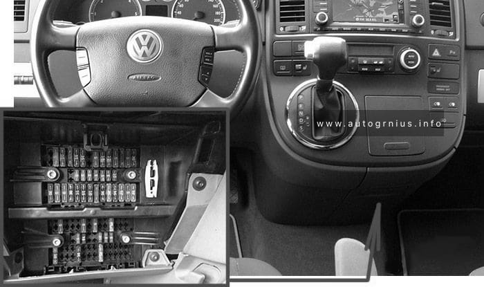
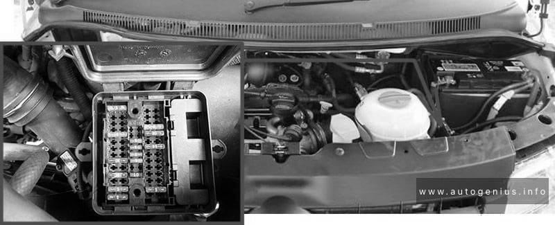
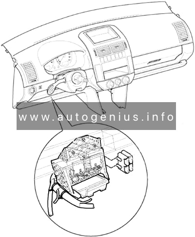
Fuse box location
1 – Pre-Fuse box (Fuse holder A -SA-);
2 – Relay carrier under electronics box;
3 – Terminal 30 wiring junction;
4 – Heated windscreen relay;
In plenum chamber next to engine control unit;
5 – Fuses on left under dash panel;
6 – Fuse holder on the right side edge of the instrument panel (Fuse holder D -SD-);
7 – Relays on onboard supply control unit;
8 – Fuses in the luggage compartment (Fuse holder F -SF-);
There are additional fuses above the vehicle battery behind the panel on the left side of the luggage Compartment.
9 – Fuse 2 (30) -S205- (60 A);
10 – Fuse holder on the left side edge of the instrument panel (Fuse holder C -SC-);
11 – Relay carrier 1 on left under dash panel;
12 – Relay carrier 2 on left under dash panel;
13 – Relay carrier under electronics box;
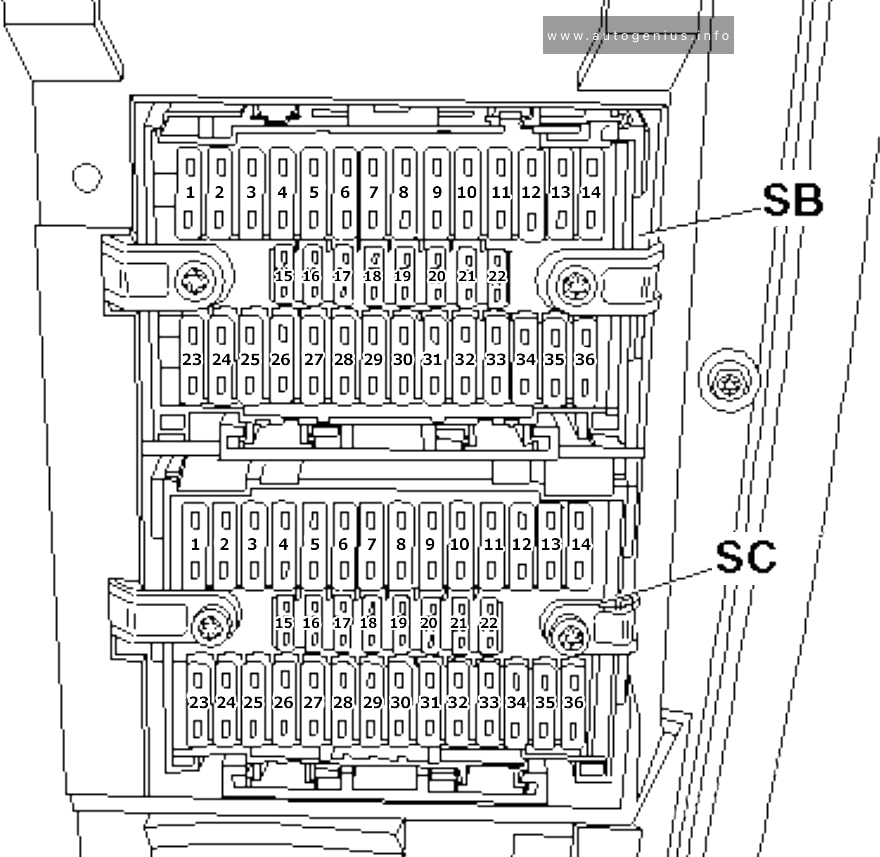
14 – Fuse box in the Engine compartment (Fuse holder B -SB-)
Passenger compartment
Fuse box location
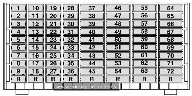
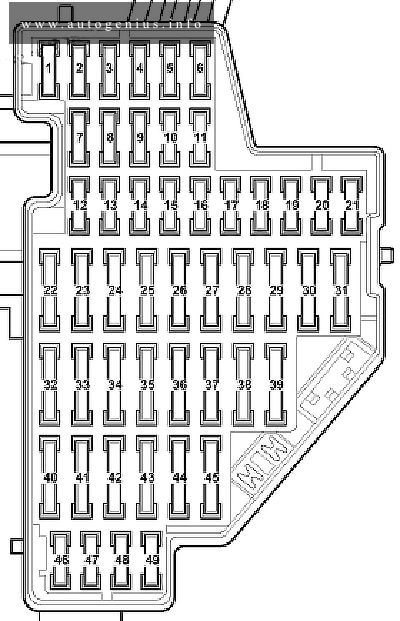
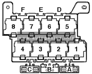
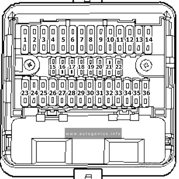
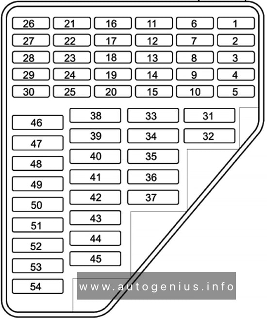
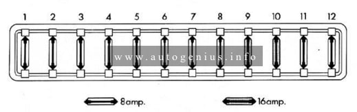
Fuse Box in the Left side edge of the instrument panel
Fuse box diagram
Assignment of the fuses in the passenger compartment (instrument panel – left side)
| № | Amp | Function/component |
|---|---|---|
| 1 | 10 | High-pressure sender -G65- Air quality sensor -G238- Oil level and oil temperature sender -G266- Fresh air blower relay -J13- DC./AC converter with socket, 12 V – 230 V -U13- Automatic anti-dazzle interior mirror -Y7- Heated rear left seat switch with regulator -E128- Heated rear right seat switch with regulator -E129- |
| 2 | 5 | Light switch -E1- TCS and ESP button -E256- Auto-hold button -E540- ABS control unit -J104- Power steering control unit -J500- Control unit for electromechanical parking brake -J540- |
| 3 | 10 | Current supply relay -J16- Heater element for crankcase breather -N79- Gas injection valve 1-N366- Gas injection valve 2 -N367- Gas injection valve 3 -N368- Gas injection valve 4 -N369- |
| 4 | 10 | Rear roller blind switch -E149- Start/Stop operation button -E693- Electronically controlled damping control unit -J250- Adaptive cruise control unit -J428- Parking aid control unit -J446- Trailer detector control unit -J345- Park assist steering control unit -J791- Front camera for driver assist systems -R242- Diagnostic connection -U31- |
| 5 | 10 | Headlight range control regulator -E102- Left headlight range control motor -V48- Right headlight range control motor -V49- Front left headlight (Only right-hand drive models) -MX1- |
| 6 | 10 | All-wheel drive control unit -J492- |
| 7 | 5 | Control unit in dash panel insert -J285- Data bus diagnostic interface -J533- |
| 8 | 10 | Front right headlight -MX2- (Only right-hand drive models) |
| 9 | 10 | Airbag control unit -J234- Front passenger side airbag deactivated warning lamp -K145- |
| 10 | 10 | Air mass meter -G70- Voltage stabiliser -J532- Fuel pump control unit -J538- Engine control unit -J623- Terminal 50 voltage supply relay -J682- Voltage supply relay 2 -J710- Starter relay 1 -J906- Starter relay 2 -J907- |
| 11 | 5 | Warning buzzer pedal switch on front passenger side -F349- (Only applicable to special vehicles) |
| 12 | 20 | Convenience system central control unit -J393- Front passenger door control unit (Only CC) -J387- Rear passenger side door control unit (Only CC) -J927- |
| 13 | 10 | Light switch -E1-Selector lever -E313- ABS control unit -J 104- Handbrake warning lamp -K139- Diagnostic connection -U31- ABS control unit -J104- T38/15 |
| 14 | 10 | Interior monitor send and receive module 1 -G303- Alarm horn -H12- |
| 15 | 10 | Rain and light sensor -G397- Heated rear window relay -J9- Heated windscreen relay -J47- Climatronic control unit -J255- Air conditioning system control unit -J301- Reversing camera system control unit -J772- Control unit for terminal control and engine start -J942- Remote control receiver for auxiliary coolant heater -R149- Tyre Pressure Monitoring System control unit -J502- |
| 16 | 10 | Electronic ignition lock -D9- Electronic steering column lock control unit -J764- Control unit for terminal control and engine start -J942- |
| 17 | 15 | Driver door control unit (Only CC) -J386- Rear driver side door control unit (Only CC) -J926- Not used (from May 2012) |
| 18 | 3A | Onboard supply control unit -J519- Voltage stabiliser -J532- Engine control unit -J623- Voltage supply relay 2 -J710- |
| 19 | – | Not used |
| 20 | – | Not used |
| 21 | 10 | Rear roller blind control unit -J262- |
| 22 | 20 | Control unit for electromechanical parking brake -J540- |
| 23 | 15 | Trailer detector control unit -J345- Electronically controlled damping control unit (Only right-hand drive models) -J250- |
| 24 | 20 | Control unit for electromechanical parking brake -J540- |
| 25 | 5 (Only models with emergency call module) 15 (Only models with trailer socket) 30 (Only right-hand drive models) |
Emergency assistance call button -E276- Trailer detector control unit -J345- Sunroof roller blind control unit (Only right-hand drive models) -J394- |
| 26 | 20 | Onboard supply control unit -J519- |
| 27 | 15 (Only models with a petrol engine) 20 (Only models with a diesel engine) |
Fuel pump control unit (Only models with a petrol engine) -J538- Fuel pump relay (Only models with a diesel engine) -J17- Electric fuel pump 2 relay (Only models with a diesel engine) -J49- |
| 28 | 30 | Driver door control unit (Only left-hand drive models) -J386- Rear driver side door control unit (Only left-hand drive models) -J926- Front passenger door control unit (Only right-hand drive models) -J387- Rear passenger side door control unit (Only right-hand drive models) -J927- |
| 29 | 20 | Heated rear seats control unit -J786- |
| 30 | 20 (Only saloon) 30 (Only estate) |
Sliding sunroof adjustment control unit -J245- |
| 31 | 30 | DC/AC converter with socket, 12 V-230 V -U13- |
| 32 | 30 | Heated rear window relay -J9- |
| 33 | 30 | Headlight washer system relay -J39- |
| 34 | 25 | Heated front seats control unit -J774- |
| 35 | 15 (Only right-hand drive models) | Rear lid control unit (Only right-hand drive models) -J605- Driver seat lumbar support adjustment switch (Only left-hand drive models) -E176- (from May 2012) |
| 36 | 15 | Driver seat lumbar support adjustment switch -E176- Trailer voltage supply relay -J941- (from May 2012) |
| 37 | 20 (Only left-hand drive models) 30 (Only right-hand drive models) |
Trailer detector control unit (Only left-hand drive models) -J345- Rear lid control unit 2 (Only right-hand drive models) -J756- |
| 38 | 40 (Only models with auxiliary heating) | Fresh air blower relay (Only models with Climatic) -J13- Fresh air blower control unit (Only models with Climatronic) -J126- |
| 39 | 5 | Selector lever -E313- Reversing light switch -F4- Mechatronic unit for dual clutch gearbox -J743- |
| 40 | 20 | Onboard supply control unit -J519- Rear window wiper motor -V12- Windscreen and rear window washer pump -V59- |
| 41 | 20 | Onboard supply control unit -J519- Cigarette lighter -U1- Rear cigarette lighter -U9- |
| 42 | 15 | 12 V socket -U5- |
| 43 | 20 | Auxiliary heater control unit -J364- (Only models with second battery) |
| 44 | 30 | Driver door control unit (Only right-hand drive models) -J386- Rear driver side door control unit (Only right-hand drive models) -J926- Front passenger door control unit (Only left-hand drive models) -J387- Rear passenger side door control unit (Only left-hand drive models) -J927- |
| 45 | 20 | Auxiliary heater operation relay -J485- (Only models with second battery) |
| 46 | – | Not used |
| 47 | 5 (Only models with start/stop system) | Analogue clock -Y- TV tuner -R78- Mobile telephone operating electronics control unit -J412- Control unit for navigation system (Only models with equipment for Korea) -J856- |
| 48 | 5 | Control unit in dash panel insert -J285- (Only models with start/stop system) |
| 49 | – | Not used |
Fuse box location
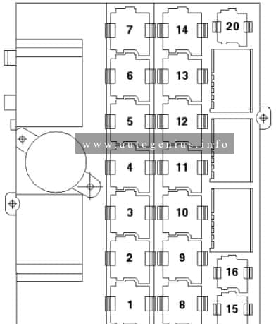
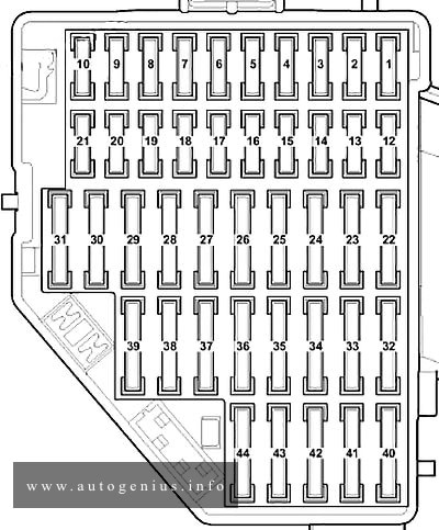
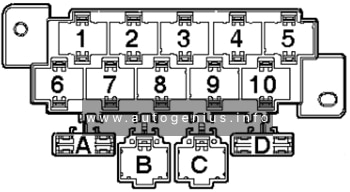
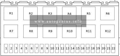
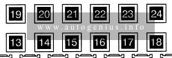
Fuse Box in the righteft side edge of the instrument panel
Fuse box diagram
Assignment of the fuses in the passenger compartment (instrument panel – right side)
| № | Amp | Function/component |
|---|---|---|
| 1 | 30 15 (Only right-hand drive models) |
Rear lid control unit (Only estate) (left-hand drive models) -J605- Trailer detector control unit (Only right-hand drive models) -J345- |
| 2 | 30 20 (Only right-hand drive models) |
Rear lid control unit 2 (Only estate (left-hand drive models)) -J756- Trailer detector control unit (Only right-hand drive models) -J345- |
| 3 | 30 15 (Only right-hand drive models) |
Sunroof roller blind control unit (Only estate (left-hand drive models)) -J394- Trailer detector control unit (Only right-hand drive models) -J345- |
| 4 | 15 | Electronically controlled damping control unit -J250- Not used (Only right-hand drive models) |
| 5 | – | Not used |
| 6 | – | Not used |
| 7 | – | Not used |
| 8 | – | Not used |
| 9 | – | Not used |
| 10 | – | Not used |
| 11 | – | Not used |
| 12 | – | Not used |
| 13 | Special vehicles | |
| 14 | Special vehicles | |
| 15 | Special vehicles | |
| 16 | Charging station for hand-held 2-way radio -U24- Charging station 2 for hand-held 2-way radio -U28- Charging station 2 for torch -U29- |
|
| 17 | Special vehicles | |
| 18 | Special vehicles | |
| 19 | Special vehicles | |
| 20 | Special vehicles | |
| 21 | Special vehicles | |
| 22 | Special vehicles | |
| 23 | Special vehicles | |
| 24 | Special vehicles |
Fuse box location
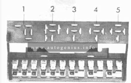
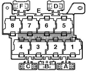
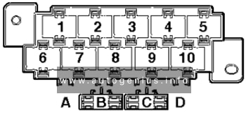
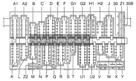
Fuses on left under dash panel
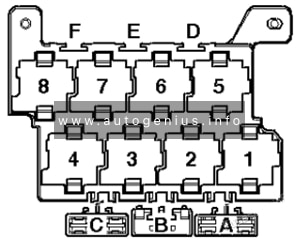
Fuse box diagram
Assignment of the passenger compartment (left under dash panel)
| № | Amp | Function/component |
|---|---|---|
| A | – | Not assigned |
| B | – | Driver seat adjustment thermal fuse 1 -S44- |
| Relays | ||
| 1 | Fresh air blower relay -J13- (Climatic with auxiliary heater) | |
| 2 | Auxiliary heater operation relay -J485- (Climatic with auxiliary heater) | |
| 3 | Auxiliary heater operation relay -J485- (Diesel engine with auxiliary heater) | |
| 4 | Not used | |
| 5 | Continued coolant circulation relay -J151- (only 1.8l / 2.0l TFSI) Current supply relay -J17- |
|
| 6 | Terminal 50 voltage supply relay -J682- (not for models with start/stop system) | |
| 7 | Voltage supply relay 2 -J710- (not for models with start/stop system) | |
| 8 | Voltage supply relay 2 -J710- (not for models with start/stop system) |
Fuse box location
Relay carrier 1 on left under dash panel
Fuse box diagram
Relay carrier 1 on left under dash panel
| № | Function/component |
|---|---|
| 1 | Vacant |
| 2 | Vacant |
| 3 | Vacant |
| 4 | Vacant |
| 5 | Vacant |
| 6 | Vacant |
Fuse box location
Relay carrier 2 on left under dash panel
Fuse box diagram
Relay carrier 2 on left under dash panel
| № | Function/component |
|---|---|
| 1 | Heated rear window relay -J9- (645) |
| 2 | Terminal 15 voltage supply relay -J329- (645) |
| 3 | Dual tone horn relay -J4- (646) Headlight washer system relay -J39- (646) |
| 4 | Trailer voltage supply relay -J941- (from May 2012) Vacant |
| 5 | X-contact relief relay -J59- (644) |
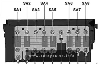
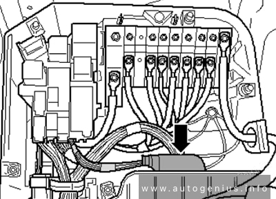
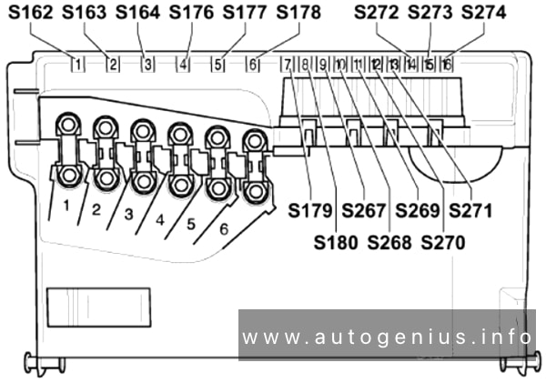
Pre-Fuse box (type 1)
Fuse box diagram
Pre-Fuse box, type 1
| № | A | Function/component |
|---|---|---|
| SA1 | 150 / 180 | Alternator -C- |
| SA2 | 80 | Electromechanical power steering motor -V187- |
| SA3 | 50 | Radiator fan control unit -J293- |
| SA4 | 60 | Fuse 12 on fuse holder C -SC12- to fuse 17 on fuse holder C -SC17- Fuse 22 on fuse holder C -SC22- to fuse 27 on fuse holder C -SC27- Fuse 28 on fuse holder C -SC28- Fuse 44 on fuse holder C -SC44- Fuse 46 on fuse holder C -SC46- |
| SA5 | 80 | Fuse 29 on fuse holder C -SC29- to fuse 31 on fuse holder C -SC31- |
| SA6 | 70 | Fuse 32 on fuse holder C -SC32- to fuse 37 on fuse holder C -SC37- |
| SA7 | 60 | Second battery charging circuit relay -J713- High heat output relay -J360- Fuse 38 on fuse holder C -SC38- Fuse 43 on fuse holder C -SC43- Fuse 45 on fuse holder C -SC45- |
| SA8 | 40 | ABS control unit -J104- |
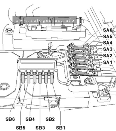
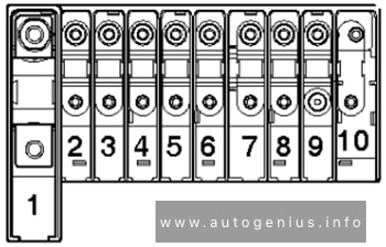
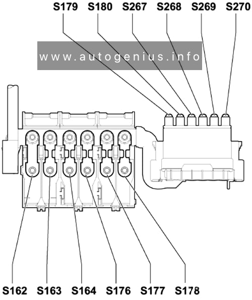
Pre-Fuse box (type 2)
Fuse box diagram
Pre-Fuse box, type 2
| No | A | Function/component |
|---|---|---|
| SA1 | 150/180 | Alternator -C- |
| SA2 | 80 | Electromechanical power steering motor -V187- |
| SA3 | 60 | Fuse 32 on fuse holder C -SC32- to fuse 37 on fuse holder C -SC37- |
| SA4 | 50 | Radiator fan control unit -J293- |
| SA5 | – | Not used |
| SA6 | 80 | Fuse 29 on fuse holder C -SC29- to fuse 31 on fuse holder C -SC31- |
| SA7 | 40 | ABS control unit -J104- |
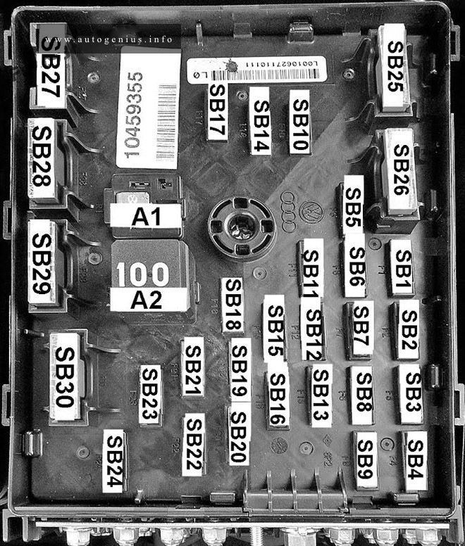
Engine compartment fuse box
Fuse box diagram (type 1)
Assignment of the fuses in the engine compartment, type 1
| № | Amp | Function/component |
|---|---|---|
| SB1 | 15 | Mechatronic unit for dual clutch gearbox (for CNG models only) (Only ethanol vehicles) -J743- (from May 2012) |
| SB2 | 30 | ABS control unit -J104- |
| SB3 | 20 | Treble horn -H2- Bass horn -H7- Dual tone horn relay -J4- |
| SB4 | 20 | Trailer detector control unit -J345- |
| SB5 | 5 | Battery monitoring control unit -J367- Onboard supply control unit -J519- |
| SB6 | 15 / 40 | Mechatronic unit for dual clutch gearbox (Only models with diesel engines) (Only for petrol engine with forced induction) -J743- Low heat output relay (for CNG models only) (Only for petrol engine without forced induction) -J359- |
| SB7 | 15 (Only models with radio), (Only models with start/stop system) 20 (Only models with navigation system), (Only models with start/stop system) 30 (Only models with start/stop system) |
Radio -R- Control unit with display for radio and navigation -J503- Voltage stabiliser (Only models with start/stop system) -J532- |
| SB8 | 30 | Mechatronic unit for dual clutch gearbox -J743- |
| SB9 | 5 | Steering column electronics control unit -J527- |
| SB10 | 20 | Ignition coil 1 with output stage -N70- Ignition coil 2 with output stage -N 127- Ignition coil 3 with output stage -N291- Ignition coil 4 with output stage -N292- Fuel pressure regulating valve -N276- Fuel metering valve -N290- |
| SB11 | 5 | Control unit in dash panel insert -J285- |
| SB12 | 5 | TV tuner -R78- Mobile telephone operating electronics control unit -J412- Analogue clock -Y- Control unit for navigation system (Only models with equipment for Korea) -J856- |
| SB13 | 10 | Motronic current supply relay -J271- Terminal 30 voltage supply relay -J317- Engine control unit -J623- |
| SB14 | 25 (Only models with a petrol engine) 30 (Only models with diesel engines) |
Engine control unit -j623- Engine control unit -j623- |
| SB15 | 5 | Data bus diagnostic interface -J533- |
| SB16 | 10 / 15 | Charge pressure control solenoid valve (Only models with diesel engines) -N75- Exhaust gas recirculation cooler changeover valve -N345- Magnetic clutch for supercharger (Only models with a petrol engine) -N421- Continued coolant circulation relay (Only models with a petrol engine) -J151- Continued coolant circulation pump (Only models with a petrol engine) -V51- Coolant circulation pump 2 -V178- |
| SB17 | 10 40 (Only models with auxiliary air heater) |
Fuel pressure regulating valve -N276- Fuel tank shut-off valve 1-N361- Fuel tank shut-off valve 2 -N362- Fuel tank shut-off valve 3 -N363- Coolant circulation pump -V50- Low heat output relay (Only models with auxiliary air heater) -J359- |
| SB18 | 10 (Only models without reducing agent metering system) 30 (Only models with reducing agent metering system) |
Fuel quality sender -G446- High-pressure valve for gas mode -N372- |
| SB19 | 30 | Amplifier -R12- Special vehicle control unit (Only applicable to special vehicles) -J608- |
| SB20 | 5 15 (for CNG models only), (Only ethanol vehicles) |
Brake light switch -F- Clutch position sender -G476- Low heat output relay -J359- High heat output relay -J360- Engine component current supply relay -J757- Fuel pressure regulating valve -N276- |
| SB21 | 20 | Auxiliary heater control unit -J364- |
| SB22 | 30 | Wiper motor control unit -J400- |
| SB23 | 10 | Brake light switch -F- Air mass meter -G70- Clutch position sender -G476- Fuel pump relay -J17- Automatic glow period control unit -J179- Radiator fan control unit -J293- Additional coolant pump relay -J496- Charge pressure control solenoid valve -N75- Activated charcoal filter solenoid valve 1-N80- Camshaft control valve 1-N205- Turbocharger air recirculation valve -N249- Intake manifold flap valve -N316- Valve for oil pressure control -N428- |
| SB24 | 10 (Only models with diesel engines), (Only models without reducing agent metering system) 15 |
Lambda probe heater -Z19- Lambda probe 1 heater after catalytic converter -Z29- NOx sender 2 control unit (Only models with reducing agent metering system) -J881- |
| SB25 | 40 | Onboard supply control unit -J519- |
| SB26 | 40 | Onboard supply control unit -J519- |
| SB27 | 60 | Heated windscreen relay -J47- |
| SB28 | 50 | Automatic glow period control unit (Only models with diesel engines) -J179- |
| SB29 | 50 | Fuse 38 on fuse holder C (Only models with air conditioning system/Climatronic) -SC38- Fuse 40 on fuse holder C -SC40- to fuse 42 on fuse holder C -SC42 -X- contact relief relay -J59- |
| SB30 | 40 | Terminal 15 voltage supply relay -J329- Fuse 1 on fuse holder C -SCI- to fuse 11 on fuse holder C -SC11- Fuse 20 on fuse holder C -SC20- Fuse 21 on fuse holder C -SC21- Fuse 39 on fuse holder C -SC39- Fuse 18 on fuse holder C (Only models with start/stop system) -SC18- |
| Relays | ||
| A1 | Engine component current supply relay -J757- | |
| A2 | Terminal 30 voltage supply relay -J317- (Diesel engine) Motronic current supply relay -J271- (Petrol engine) |
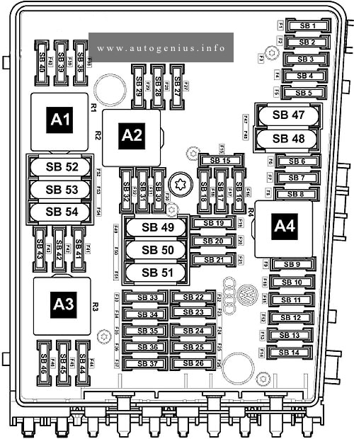
Engine compartment fuse box
Fuse box diagram (type 2)
Assignment of the fuses in the engine compartment, type 2
| № | Amp | Function/component |
|---|---|---|
| SB1 | 5 (Only models with automatic gearbox) 10 (Only models with dual clutch gearbox) |
Automatic gearbox control unit -J217- Mechatronic unit for dual clutch gearbox -J743- |
| SB2 | 30 | ABS control unit -J104- |
| SB3 | 15 | Trailer detector control unit -J345- |
| SB4 | – | Not used |
| SB5 | 20 | Treble horn -H2- Bass horn -H7- Dual tone horn relay -J4- |
| SB6 | 20 | Ignition coil 1 with output stage -N70- Ignition coil 2 with output stage -N 127- Ignition coil 3 with output stage -N291- Ignition coil 4 with output stage -N292- Ignition coil 5 with output stage -N323- Ignition coil 6 with output stage -N324- |
| SB7 | 15 | Fuel pressure regulating valve -N276- |
| SB8 | 5 (Only for countries with hot climate) 10 |
Brake light switch -F- Continued coolant circulation relay -J151- Radiator fan control unit -J293- Activated charcoal filter solenoid valve 1 -N80- Camshaft control valve 1 -N205- Exhaust camshaft control valve 1 -N318- |
| SB9 | 5 | Circulation pump relay -J160- |
| SB10 | 10 | Lambda probe 1 heater after catalytic converter -Z29- Lambda probe 2 heater after catalytic converter -Z30- |
| SB11 | 25 30 (Only for countries with hot climate) |
Engine control unit -J623- |
| SB12 | 10 (Only for countries with hot climate) 20 |
Lambda probe heater -Z19- Lambda probe 2 heater -Z28- |
| SB13 | – | Not used |
| SB14 | – | Not used |
| SB15 | 10 | Continued coolant circulation pump -V51- |
| SB16 | 5 | Steering column electronics control unit -J527- |
| SB17 | 5 | Control unit in dash panel insert -J285- |
| SB18 | 30 | Amplifier -R12- |
| SB19 | 15 (Only models with radio), (Only models with start/stop system) 20 (Only models with navigation system), (Only models with start/stop system) 30 (Only models with start/stop system) |
Radio -R- Control unit with display for radio and navigation -J503- Voltage stabiliser (Only models with start/stop system) -J532- |
| SB20 | 5 | Analogue clock -Y- TV tuner -R78- Mobile telephone operating electronics control unit -J412- Control unit for navigation system -J856- (Only models with equipment for Korea) |
| SB21 | – | Not used |
| SB22 | – | Not used |
| SB23 | – | Not used |
| SB24 | 5 | Data bus diagnostic interface -J533- |
| SB25 | – | Not used |
| SB26 | 10 | Motronic current supply relay -J271- Engine control unit -J623- |
| SB27 | – | Not used |
| SB28 | – | Not used |
| SB29 | – | Not used |
| SB30 | 20 | Auxiliary heater control unit -J364- |
| SB31 | 30 | Wiper motor control unit -J400- |
| SB32 | – | Not used |
| SB33 | – | Not used |
| SB34 | – | Not used |
| SB35 | 20 40 (Only for countries with hot climate) |
Auxiliary heater operation relay -J485- Low heat output relay (Only for countries with hot climate) -J359- |
| SB36 | – | Not used |
| SB37 | – | Not used |
| SB38 | – | Not used |
| SB39 | – | Not used |
| SB40 | – | Not used |
| SB41 | – | Not used |
| SB42 | – | Not used |
| SB43 | – | Not used |
| SB44 | – | Not used |
| SB45 | – | Not used |
| SB46 | – | Not used |
| SB47 | 40 | Onboard supply control unit -J519- |
| SB48 | 40 | Onboard supply control unit -J519- |
| SB49 | 50 | Terminal 15 voltage supply relay -J329- Fuse 6 on fuse holder C -SC6- to fuse 11 on fuse holder C -SC11- Fuse 20 on fuse holder C -SC20- Fuse 21 on fuse holder C -SC21- Fuse 39 on fuse holder C -SC39- Fuse 18 on fuse holder C (Only models with start/stop system) -SC18- |
| SB50 | – | Not used |
| SB51 | 60 | High heat output relay -J360- (Only for countries with hot climate) |
| SB52 | 60 | Heated windscreen relay -J47- |
| SB53 | 50 | X-contact relief relay -J59- |
| SB54 | 50 | Automatic glow period control unit -J179- (Only for countries with hot climate) |
| Relays | ||
| A1 | Current bridge Relay for gas shut-off valves -J908- | |
| A2 | Continued coolant circulation relay -J151- (100) | |
| A3 | Vacant | |
| A4 | Main relay -J271- (100) |
Relay carrier under the electronics box
Fuse box diagram
Relay carrier under electronics box
| № | Function/component |
|---|---|
| 1 | Starter relay 1 -J906- (643) – For models with start/stop system only |
| 2 | Automatic glow period control unit -J179- (457) |
| 3 | Vacant |
| 4 | Low heat output relay -J359- (53) |
| 5 | High heat output relay -J360- (100) |
| 6 | Starter relay 2 -J907- (489) – For models with start/stop system only |
Heated windscreen relay
Fuse box location
In plenum chamber next to engine control unit.
Luggage compartment
Fuse box diagram
Fuses in the luggage compartment
| № | Amp | Function/component |
|---|---|---|
| 1 | 30 | Left fuse holder (SC12 – SC 17, SC27, SC29 – SC31, SC44) |
| 2 | 80 | Fuses in E-box (SB16 – SB26, SB49, SB50) |
| 3 | 125 | Power supply E-box |
| 4 | 5 | Onboard supply control unit -J519- Battery monitor control unit -J367- |
WARNING: Terminal and harness assignments for individual connectors will vary depending on vehicle equipment level, model, and market.