MG ZS  EV (2019 – 2021) – fuse and relay box diagram

MG ZS  EV (2019 – 2021) – fuse and relay box diagram

Year of production: 2019, 2020, 2021


The pre-facelift MG ZS EV, a subcompact electric crossover, was produced from 2019 to 2021. This article includes fuse box diagrams for the 2019, 2020, and 2021 models, provides details on the locations of the fuse panels inside the vehicle, and explains the function of each fuse (fuse layout).


Passenger Compartment Fuse Box

Fuse Box Location

The fuse panel is located below the glove box at the front passenger side.


Fuse Box Diagram
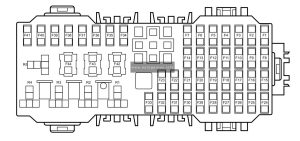
MG ZS EV (2019 - 2021) - fuse and relay box diagram - passenger compartment fuse box
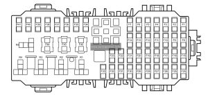
MG ZS EV (2019 – 2021) – fuse and relay box diagram – passenger compartment fuse box


Assignment of the fuses in the passenger compartment

No.
А
Function
F1 5A Charging Plug Unlock Relay, Charging Plug Lock Relay
F2 10A Diagnostic Socket
F3 5A Charger, EVCC
F4 15A Front Wash Relay, Rear Wash Relay
F5 5A SDM
F6 5A HV PTC, ESS PTC
F7 10A ESS (High Voltage Battery)
F8 5A TPMS, EPB Switch
F9 5A VCU
F10 10A PACM
F11 5A PEPS
F12
F13 30A Driver Seat Adjust Switch
F14 5A IMMO Coil
F15 15A Front Power Socket
F16 5A Rear USB Charge Module, Master Light Switch, Headlamp Assembly
F17
F18 30A Rear Left Window Lift Switch
F19 30A Passenger Window Lift Switch
F20 30A Rear Right Window Lift Switch
F21 30A Driver Window Lift Motor
F22 10A Heated Mirrors
F23 25A Rear Windshield Assembly
F24 20A FICM, IFP, DAB
F25 15A ETC, ACFP
F26 5A Instrument Pack
F27 10A Driver Door Switch Pack, Master Light Switch
F28 5A RLS, Master Radar
F29 10A Gateway
F30 10A Gateway
F31 30A Sunroof ECU
F32 30A Sunroof ECU
F33 5A SCU
F34 10A ESCL
F35 15A Super Lock Relay
F36
F37
F38
F39
F40
F41
F42 30A EPB
F43 30A EPB
F44

Engine Compartment Fuse Box

Fuse Box Diagram
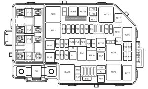
MG ZS EV (2019 - 2021) - fuse and relay box diagram - engine compartment fuse box
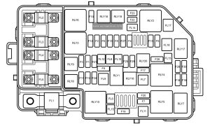
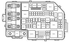
MG ZS EV (2019 – 2021) – fuse and relay box diagram – engine compartment fuse box


Assignment of the fuses in the engine compartment

Amps Function
FL1 I50A PEB
FL2 80A EPS
FL3 40A Cooling Fan Relay Pack
FL4 80A Passenger Compartment Fusebox Fuse F18, F19, F20, F21, F34, F35, F42, F43
FL5 80A Passenger Compartment Fusebox Fuse F1, F2, F3, F4, F5, F6, F7, F8, F9, F10, F11, F13, F14, F24, F25, F26, F27, F28, F29, F30, F31, F32, F33, HRW Relay
FL6 25A SCS Valve
FL7 30A Blower Motor, ETC
FL8 20A BCM
FL9 40A SCS Pump
FL10 30A BCM
FL11
FL12 20A BCM
FL13
FL14
FL15 30A KLR Relay
FL16
FL17 40A EVP Relay
F1
F2 15A PEB Water Pump, Cooling Fan Relay Pack
F3
F4
F5 10A EVAP
F6
F7 30A Wiper Enable Relay, Wiper Speed Relay
F8
F9
F10 10A Main Beam – RH
F11 10A Main Beam – LH
F12
F13 15A Horn Relay
F14
F15 5A Brake Pedal Switch
F16 15A Rear Wiper Relay
F17 15A ESS PWM Pump Relay
F18 5A SDM
F19 5A VCU
F20
F21 15A BCM
F22 10A Seat Heat Relay – LH
F23 10A Seat Heat Relay – RH
F24 10A PEB
F25 15A BCM
F26
F27 5A BCM, EVP Relay, Front Breath Lamp
F28
F29
F30 10A BCM, SCU, Instrument Pack, ADM, FVCM, Front Radar

WARNING: Terminal and harness assignments for individual connectors will vary depending on vehicle equipment level, model, and market.

MG ZS (2021 – 2023) – fuse and relay box diagram

MG ZS (2021 – 2023) – fuse and relay box diagram

Year of production: 2021, 2022, 2023


The pre-facelift MG ZS, a subcompact crossover, was produced from 2017 to 2020. This article includes fuse box diagrams for the 2017 through 2020 models, provides details on the locations of the fuse panels inside the vehicle, and explains the function of each fuse (fuse layout).


Fuse Box Location

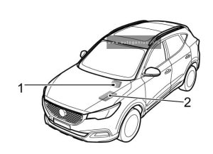
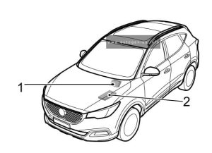
MG ZS (2021 - 2023) - fuse and relay box location

MG ZS (2021 – 2023) – fuse and relay box location


  1. Passenger Compartment Fuse Box(below the glove box at the front passenger side
  2. Engine Compartment Fuse Box(at the left side of the Engine Compartment


Passenger Compartment Fuse Box

Fuse Box Diagram

MG ZS (2021 - 2023) - fuse and relay box diagram - passenger compartment fuse box
MG ZS (2021 – 2023) – fuse and relay box diagram – passenger compartment fuse box


Assignment of the fuses in the passenger compartment

No.
А
Function
F1 15A Front Washer Relay, Rear Washer Relay
F2 10A Diagnostic Socket
F3 5A PRND Display
F4 10A Front Left Seat Heating Relay
F5 10A Airbag ECU (SDM)
F6 10A Keyless Start/Stop Switch, Gateway
F7 30A Driver Seat Adjust Switch
F8 15A Super Lock Relay
F9
F10
F11
F12 5A Left Rear Driving Assistance Radar
F13
F14
F15 15A Front Power Socket
F16 5A Front Courtesy Lamp, Outside Mirror and Master Light Height Adjust Switch, Top USB, Left Headlamp Assembly, Right Headlamp Assembly
F17 5A Rear USB
F18 5A EPB Switch
F19 5A Outside Mirror and Master Light Height Adjust Switch, Rain Light Sensor
F20 10A Front Right Seat Heating Relay
F21 10A 360° View Module, Passenger Compartment Fuse F12
F22 10A Exterior Mirrors Heating Element
F23 25A Rear Windscreen Heating Element
F24 20A Front Central Display, Front Infotainment Control Module
F25 10A Electronic Temperature Controller
F26 5A Instrument Pack
F27 10A Transmission Control Module – AT
F28 5A Information Faceplate
F29 30A Sunroof
F30 5A DAB Module
F31 5A Tyre Pressure Monitoring System
F32 10A Electronic Steering Column Lock
F33 30A Sunroof
F34
F35
F36
F37
F38
F39
F40
F41
F42 25A Stability Control Module(Valve) – MT
F42 40A Stability Control Module(Valve) – AT
F43 30A Passenger Window lift Switch, Rear Left Window Lift Switch
F44 30A Driver Door Switch Pack, Driver Window Lifter, Rear Right Window Lift Switch

Engine Compartment Fuse Box

Fuse Box Diagram

MG ZS (2021 - 2023) - fuse and relay box diagram - engine compartment fuse box
MG ZS (2021 – 2023) – fuse and relay box diagram – engine compartment fuse box


Assignment of the fuses in the engine compartment

Amps Function
FL1 I50A Alternator
FL2 80A Electric Power Steering Module
FL3 40A Cooling Fan Relay Pack
FL4 80A Windscreen/Mirror Heating Relay, Passenger Compartment Fuse F18, F19, F20, F21, F42, F43, F44
FL5 80A KLR Relay, Passenger Compartment Fuse F1, F2, F3, F4, F5, F6, F7, F8, F24, F25, F26, F27, F28, F29, F30, F31, F32, F33
FL6
FL7 40A Electronic Temperature Controller, Blower
FL8 20A Body Control Module
FL9 40A Stability Control Module(Pump)
FL10
FL11
FL12
FL13 30A Starter Relay
FL14
FL15
FL16 30A DC/DC Convertor
FL17
F1 10A Right Headlamp Assembly
F2 15A Downstream Lambda Sensor, Upstream Lambda Sensor, Positive Temperature Coefficient (1.5L), Intake Variable Camshaft Timing (1.0T), Exhaust Variable Camshaft Timing (1.0T), Oil Control Valve (1.0T), Canister Purge Valve (1.0T)
F3 10A Left Headlamp Assembly
F4 10A Compressor Relay
F5 5A Engine Control Module
F6 10A Fuel lnjector (1.5L)
F7 30A Front Wiper Enable Relay, Front Wiper High/Low Speed Relay
F8 5A Cooling Fan Relay Pack, Brake Pedal Switch, Fuel Pump Relay, AC Pressure Switch, Neutral Switch (1.5L)
F9 20A Fuel Pump Relay
F10 10A Right Headlamp Assembly
F11 10A Left Headlamp Assembly
F12 30A Ignition Coil, Engine Control Module
F13 15A Horn Relay
F14
F15 10A Intake Variable Camshaft Timing (1.5L), Exhaust Variable Camshaft Timing (1.5L), Canister Purge Valve (1.5L), Electronic Thermostat (1.0T), Electronic Water Pump (1.0T), Dump Valve (1.0T), Waste Gate Control Valve (1.0T), Clutch Master Cylinder Sensor (1.0T)
F16 15A Rear Wiper Relay
F17 10A Fog Lamp Relay
F18 5A Airbag ECU (SDM)
F19 5A Instrument Pack, Front Detect Radar, Front View Control Module, Shifter Mechanism, Reverse Lamp Switch, DC/DC Convertor, Airbag Display Module
F20 5A Engine Control Module
F21 25A Body Control Module
F22
F23
F24
F25 30A Body Control Module
F26
F27 15A Body Control Module
F28
F29
F30 5A Engine Control Module

WARNING: Terminal and harness assignments for individual connectors will vary depending on vehicle equipment level, model, and market.
MG ZS (2017 – 2020) – fuse and relay box diagram

MG ZS (2017 – 2020) – fuse and relay box diagram

Year of production: 2017, 2018, 2019, 2020


The pre-facelift MG ZS, a subcompact crossover, was produced from 2017 to 2020. This article includes fuse box diagrams for the 2017 through 2020 models, provides details on the locations of the fuse panels inside the vehicle, and explains the function of each fuse (fuse layout).


Fuse Box Location

MG ZS (2017 - 2020) - fuse and relay box location
MG ZS (2017 – 2020) – fuse and relay box location


  1. Passenger Compartment Fuse Box(below the glove box at the front passenger side
  2. Engine Compartment Fuse Box(at the left side of the Engine Compartment


Passenger Compartment Fuse Box

Fuse Box Diagram

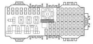
MG ZS (2017 - 2020) - fuse and relay box diagram - passenger compartment fuse box
MG ZS (2017 – 2020) – fuse and relay box diagram – passenger compartment fuse box


Assignment of the fuses in the passenger compartment

No.
А
Function
F1 15 Rear wash realy
F2 10 Rearview mirror switch, Diagnostic Socket
F3 5 Gear shift display
F4 15 Front wash relay
F5 10 Airbag ECU
F6 10 Brake pedal switch
F7 15 Super lock relay
F8
F9
F10
F11
FI2
F13
F14
FI5 15 Front power socket
FI6 5 Radio
F17 5 Front interior lamp, Blower relay
FI8 30 Rear left window lift switch
FI9 30 Passenger window lift switch
F20 30 Rear right window lift switch
F2I 30 Driver door switch pack
F22 10 Door mirror heater
F23 25 Rear window heating element
F24 15 Radio/FICM, DAB, ICE panel switch
F25 10 MTC, ETC, ETC pane
F26 5 Instrument pack
F27 10 Automatic transmission (4AT & 6AT)
F28
F29
F30 5 Ignition switch
F3I 10 TPMS
F32 5 IMMO Antenna
F33
F34
F35
F36
F37
F38
F39
F40
F41
F42
F43
F44

Engine Compartment Fuse Box

Fuse Box Diagram

MG ZS (2017 - 2020) - fuse and relay box diagram - engine compartment fuse box
MG ZS (2017 – 2020) – fuse and relay box diagram – engine compartment fuse box


Assignment of the fuses in the engine compartment

No.
А
Function
FL1 200 Alternator
FL2 80 EPS
FL3 40 Cooling fan relay pack
FL4 60 Passenger compartment fuse box fuse F18, F19, F20, F21
FL5 80 Passenger compartment fuse box fuse F1, F2, F3, F4, F5, F6, F7, F24, F25, F26, F27, F28, F29, F30, F31, Rear windscreen heater relay
FL6 25 SCS(Valve)
FL7
FL8 20 BCM
FL9 40 SCS(Pump
FL10 25 BCM
FL11 30 Blower relay
FL12
FL13 30 Starter relay
FL14 25
FL15 30 KLR relay
FL16 30 DC/DC
FL17 30
F1 10 Right dipped beam, Headlamp leveling switch, Right headlamp leveling motor
F2 15 Alternator, Pre oxygen sensor, Post oxygen sensor, Variable
valve timing valve (Intake, 1.0T), VVT valve (Exhaust, 1.0T), Canister control valve (1.0T), Oil control valve (1.0T)
F3 10 Left dipped beam, Left headlamp leveling motor
F4 10 A/C Compressor Clutch Relay
F5 5 Engine ECU
F6 10 Fuel injector(1.5L
F7 30 Front wiper enable relay, Front wiper speed relay
F8 5 Cooling fan relay pack, AC pressure switch, NTS
F9 15 Fuel pump relay
F10 10 Right main beam
F11 10 Left main beam
F12 30 Ignition coil, Engine ECU
F13 10 Horn relay
F14 30
F15 10 Intake camshaft solenoid (1.5L), Exhaust camshaft solenoid (1.5L), Canister control valve (1.5L), Clutch position sensor (1.5L), Waste gate control valve (1.0T), Electronic thermostat (1.0T), Water pump (1.0T), Variable dump valve (1.0T)
F16 15 Rear wiper relay
F17 15 Front fog relay
F18 5 Airbag ECU
F19 5 Engine ECU
F20 5 Engine ECU
F21 5 BCM
F22 10
F23 10
F24 5
F25 10 BCM
F26 15
F27 15 BCM
F28 15
F29 10
F30 10 DC/DC, Instrument pack, ETC, Reverse lamp switch, 6AT gear shift, PAB display

WARNING: Terminal and harness assignments for individual connectors will vary depending on vehicle equipment level, model, and market.